EP1806186B2 - Walzvorrichtung - Google Patents
Walzvorrichtung Download PDFInfo
- Publication number
- EP1806186B2 EP1806186B2 EP07300700.7A EP07300700A EP1806186B2 EP 1806186 B2 EP1806186 B2 EP 1806186B2 EP 07300700 A EP07300700 A EP 07300700A EP 1806186 B2 EP1806186 B2 EP 1806186B2
- Authority
- EP
- European Patent Office
- Prior art keywords
- cylinder
- replaced
- roll
- cage
- rolls
- Prior art date
- Legal status (The legal status is an assumption and is not a legal conclusion. Google has not performed a legal analysis and makes no representation as to the accuracy of the status listed.)
- Not-in-force
Links
Images


Classifications
-
- B—PERFORMING OPERATIONS; TRANSPORTING
- B21—MECHANICAL METAL-WORKING WITHOUT ESSENTIALLY REMOVING MATERIAL; PUNCHING METAL
- B21B—ROLLING OF METAL
- B21B31/00—Rolling stand structures; Mounting, adjusting, or interchanging rolls, roll mountings, or stand frames
- B21B31/08—Interchanging rolls, roll mountings, or stand frames, e.g. using C-hooks; Replacing roll chocks on roll shafts
- B21B31/10—Interchanging rolls, roll mountings, or stand frames, e.g. using C-hooks; Replacing roll chocks on roll shafts by horizontally displacing, i.e. horizontal roll changing
- B21B31/103—Manipulators or carriages therefor
-
- B—PERFORMING OPERATIONS; TRANSPORTING
- B21—MECHANICAL METAL-WORKING WITHOUT ESSENTIALLY REMOVING MATERIAL; PUNCHING METAL
- B21B—ROLLING OF METAL
- B21B13/00—Metal-rolling stands, i.e. an assembly composed of a stand frame, rolls, and accessories
- B21B13/02—Metal-rolling stands, i.e. an assembly composed of a stand frame, rolls, and accessories with axes of rolls arranged horizontally
- B21B2013/025—Quarto, four-high stands
Definitions
- the subject of the invention is that of rolling mills implementing methods for replacing the rolls of a roll stand.
- the particular field of the invention is that of rolling mills for which the working rolls are not rotated directly by drive means, but are by means of the support rollers.
- the bearing cylinders are rotated by drive means associated therewith, and in turn frictionally drive the work rolls in contact with the product to be rolled.
- This is for example the case in a "skin-pass" type mill intended to give a strip to roll a particular surface condition.
- the motor side of the roll stand (the side where the drive means are located, as opposed to the operator side) is relatively clear, at least in the vicinity of the work rolls.
- the invention does not cover the "push / pull" devices in which the device is actuated so that it pulls the cylinder to be replaced out of the cage, and then a replacement cylinder is placed in its place. the cylinder to be replaced outside the cage (by a barrel system for example). The device is actuated so that it pushes the replacement cylinder inside the cage.
- the state of the art relating to the invention is that of "push through” or “pull through” devices. According to the state of the art it is possible to choose either an installation allowing the unloading of spent cylinders on the engine side, or an installation allowing the loading of the new cylinders from the engine side.
- the rolling installation is equipped with a pusher displacement device. Actuation of this pusher device makes it possible to push a new cylinder to load it inside the cage.
- the new cylinder in turn pushes the used cylinder initially into a cage to unload it out of the cage.
- the worn cylinder is received on a carriage disposed on the other side of the cage relative to the pusher device, while the new cylinder was initially positioned, before being loaded into the cage on the side of the cage where the pusher device is located.
- the document EP 0 618 018 describes, in the context of a reversible tandem installation, such a "push" system through ". Note that one can choose to position the pusher device is the motor side or the operator side.
- the pusher device is a kind of simple piston applying, by contact on one end of the new replacement cylinder, a thrust force directed along the axis of this new cylinder.
- the new cylinder is first moved and then contacts one end of the used cylinder to be replaced.
- the new cylinder applies a contact force on the worn cylinder, directed along the axis of this worn cylinder and able to push the worn cylinder to move it out of the cage.
- This first known method has the constraint of having to be driven slowly so that, at all times, the cylinders do not acquire too much inertia which would make their displacements uncontrollable. It is also necessary that the different contact reaction forces are perfectly aligned with the axis of the rolls so that they move axially along a load direction of the cage. Otherwise, the cylinders, bearings or chocks that are equipped with the different cylinders, or other parts of the cage could be damaged.
- the rolling installation is equipped with a shooter displacement device. While one end of the caged spent cylinder has been hooked to one end of the new non-cage cylinder, the shooter is hooking the other end of the used cylinder to be replaced.
- the shooter device then applies a tractive force capable of moving the worn cylinder out of the cage.
- the cylinder pulls the new cylinder inside the cage.
- the used cylinder extracted from the cage is received on a carriage disposed on the same side as the shooter device, the new cylinder having been previously positioned, before being loaded into the cage, on the side of the opposite installation to the side where is located the shooter device. Note that one can choose to position the shooter device is the motor side or the operator side.
- the attachment of the shooter device to one end of the cylinder used in a cage, and the attachment of the other end of the worn cylinder to one end of the new cylinder without cage can be realized by cooperation between a hook and a ring.
- the ring carried by the shooter device coming into contact with the hook, carried by the corresponding end of the worn cylinder, begins to lift by rotation around a pivot.
- return means automatically lower it inside the loop formed by the hook.
- a retractable finger is then actuated to close the hook around the ring to prevent it from dislodging.
- the cylinders can then be moved by pulling.
- the difficulty lies in the fact that, after insertion of the new rolls in the cage, it is necessary to carry out a complex and expensive operation in time to disengage the hooks of the corresponding rings. In addition, this operation is generally performed manually by an operator.
- Fragmented or fragmented production which is a new form of exploitation of the rolling mills to which industries have recently turned, refers to the successive production of various rolled products, each product being produced in small quantities, for example less than 1000 tonnes. This is typically the case for rolling plants to produce special steels.
- the work rolls must be adapted. For example, in a skin-pass installation, the roughness and the hardness of the rolls will be chosen according to the state of the desired surface.
- the working cylinders used are not necessarily worn and it would not necessarily be necessary to send them to the cylinder workshop.
- the object of the invention is to propose an improved rolling installation.
- the cylinder In a first mode of operation, the cylinder is positioned replacing initially on said first side, between the displacement device and the cage; the conjugate coupling means of the displacement device are coupled to the hooking means of the replacement cylinder; the conjugate coupling means of the replacement cylinder are coupled to the hooking means of the cylinder to be replaced; and the pushing device is actuated to move the replacement roll from the first side into the cage, the replacement roll then pushing the roll to be replaced to unload it from the roll cage. the second side of the cage; and the coupling means of the coupling device of the hooking means of the cage replacement cylinder and the conjugate hooking means of the cage replacement cylinder of the hooking means of the cylinder to be replaced are removed. , the cylinder to be replaced then being in reserve on the second side of the cage.
- the replacement cylinder is initially positioned on the second side of the cage; the conjugate coupling means of the displacement device are coupled to the coupling means of the cylinder to be replaced and the conjugate coupling means of the cylinder to be replaced are coupled to the hooking means of the replacement cylinder; the pulling device is actuated to pull the cylinder to be replaced outwardly of the cage towards said first side, the cylinder to be replaced then pulling in turn the replacement cylinder from the second side towards the inside of the cage; and the conjugate hooking means of the device for displacing the hooking means of the cylinder to be replaced without cage, and the conjugate hooking means of the cylinder to be replaced outside the cage, are separated from the hooking means of the replacement cylinder.
- the decoupling step consists in closing the cage, so that the replacement cylinder is progressively displaced vertically upwards, the first side, the hooking means of the replacement cylinder disengaged the conjugate hooking means of the cylinder to be replaced, so that, at the end of the closure of the cage, the attachment means of the replacement cylinder are located in a vertical plane of insertion, perpendicular to the axis loading, conjugate attachment means of the replacement cylinder, the conjugate coupling means being in line with the hooking means in a decoupled relative position.
- the rolls are replaced while the strip to be rolled is continued.
- two working rolls arranged on either side of the strip to be rolled are changed simultaneously.
- the installation comprises at least one cage provided with a crew of cylinders whose horizontal axes are located in a vertical main plane, the crew comprising at least one cylinder to be replaced, and a cylinder displacement device arranged on a first side the cage and for translating a cylinder in the main plane along a substantially horizontal loading axis.
- the displacement device is of the pusher / shooter type
- each cylinder is provided at one end located on the first side of the attachment means and at the other end located on the second side, opposite the first side, with means for coupling.
- conjugated snagging and the displacement device is provided with conjugate coupling means, the conjugate attachment and hooking means being able to form, removably, translational couplings along the loading axis, each coupling can operate in traction or thrust.
- the displacement device when the displacement device operates in tension, it pulls the cylinder to be replaced out of the cage to the first side and said cylinder to be replaced in turn pulls the replacement cylinder from the second side towards inside the cage, or, when the displacement device is operating in thrust, it pushes the replacement cylinder from the first side into the cage, and the replacement cylinder pushes the cylinder to be replaced out of the cage towards the second side.
- the cage is such that, when it is opened, the cage cylinder is moved vertically downwards in the main plane and, when it is closed, the cage cylinder is moved vertically upwards in the plane main, and in that the coupling means and the conjugate attachment means then allow coupling and mutual decoupling by vertical relative displacement in a plane parallel to the main plane and in a vertical insertion plane perpendicular to the axis loading, so that the coupling and decoupling can be respectively performed during the opening and closing of the cage.
- the attachment means disposed on a first end of the cylinders comprises at least one attachment member provided with an insertion part arranged, in the vertical plane of insertion, at the end of an axis portion perpendicular to the insertion plane, the dimension in a horizontal direction of the insertion portion being greater than the corresponding dimension of the axis portion; and the conjugate hooking means disposed on the second end of the rolls comprise at least one conjugate hooking member provided with a vertical through recess whose side furthest from the second end of the roll is partially closed by pins forming projecting horizontally towards each other; the insertion part being able to insert and slide vertically along said recess, the axis part being able to pass between the lugs, the horizontal distance between the lugs being greater than the horizontal dimension of the part of axis but smaller than the horizontal dimension of the insertion part, to define a relative position coupled in translation along the loading axis.
- the hooking means of a cylinder of the cylinder to be replaced and the replacement cylinder, and the coupled coupling means of the displacement device allow a coupling and a mutual decoupling by relative displacement in a horizontal plane and in a vertical plane of insertion perpendicular to the axis of loading, so that the coupling can take place during the displacement of the replacement cylinder to position it on the loading axis and the decoupling can take place during the displacement of the cylinder to replace to store it off the loading axis.
- the conjugate gripping means of the displacement device comprise a conjugated gripping member provided with a horizontal groove open from above disposed perpendicular to the loading axis and adapted to receive, by horizontal approach and by vertical approach from above, an insertion part of a fastener, the vertical dimension of the insertion portion being greater than the corresponding vertical dimension of the axis portion.
- the insertion portion of the fastening member of the conjugate fastening means is in the form of a cross disposed in the vertical plane of insertion and comprises a vertical arm and a horizontal arm.
- the cylinder crew comprises a plurality of cylinders to be replaced and in that the installation makes it possible to replace said plurality of cylinders to be replaced in a single step.
- the cylinder crew comprises cylinders which are not to be replaced, and in that only said cylinders which are not to be replaced are directly rotated by suitable drive means.
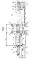
- the figures 1 and 2 are general views of a rolling plant in the presently contemplated embodiment of the invention.
- Rolling plant 1 makes it possible to roll a strip horizontally along a rolling axis A.
- the band passes between the working rolls of at least one roll stand 2 having a crew of rolls.
- the cylinder crew is constituted by a plurality of cylinders arranged one above the other and whose axes are arranged horizontally in a vertical main plane P perpendicular to the rolling axis A.
- figure 1 is a view of the installation in the main plane P.
- the rolling axis A is perpendicular to the plane of the figure 1 .
- the caged cylinder crew comprises a lower support cylinder 90, a lower working cylinder 9, an upper working cylinder 8 and an upper support cylinder 80.
- Some of the cylinders of the cylinder crew are rotated about their axis by means of drive means comprising a motor 3, a reduction device 4 and an extension 5 coupled to the cylinders to be driven.
- the rolling installation 1 is divided, on either side of the rolling axis A, between a motor side 11, where the drive means of the rolls of the cage 2 are located, and an operator side 12, disposed on the other side of the cage 2 and intended to allow access to the cage 2 to workers responsible for maintenance and handling.
- the general principle of the invention is based on the use of a pusher displacement device shooter allowing, depending on the choice made by the operator, to push or pull a cylinder train consisting of a cylinder to be replaced coupled to a replacement cylinder. Cylinders extracted from the cage are stored for use in a subsequent cycle of cylinder replacement.
- first side of the cage 2 corresponds to the side on which the displacement device is arranged.
- second side will be the side of the cage 2 opposite the first side.
- the first side coincides with the motor side 11 and the second side coincides with the operator side 12.
- an element oriented or arranged on the first side will bear the qualifier "first”, while an element oriented towards or disposed of the second side will bear the qualifier of "second".
- the head 60 of the displacement device 10 is situated at a distance D 60 from the first upright 21 of the cage 2.
- the distance D 60 essentially corresponds to the width L of the cylinders to enable the cylinder operations between the first upright 21 and the head 60 of the displacement device 10.
- the object of the invention is therefore the rapid replacement of the set of work rolls to be replaced 8 and 9, located in a cage, by a set of replacement working rolls 8 'and 9', located outside the cage.
- the method can be adapted to successively replace each work roll, it is preferable to change the lower and upper work rolls in one step.
- the replacement cylinders 8 'and 9' are provided on the second side 12 of the rolling installation 1. They are carried on a second carriage 16 adapted to move perpendicularly to the rolling axis A, along a second pair of rails 14.
- the second carriage 16 is provided with a second frame 18 receiving the lower and upper replacement cylinders 8 'and 9' in a relative position corresponding substantially to that which they must have once inserted into the roll stand 2.
- the second carriage 16 is moved, thanks to translation means 20, between a position away from the second upright 22 of the cage 2 and a position close to this second post 22.
- the position away is such that the operator side is clear to allow access to the cage 2 operators.
- the rolling plant 1 comprises a first pair of rails 13 along which a first carriage 15 can be moved.
- the displacement of the first carriage 15 is, at least in the vicinity of the first upright 21, along a direction of displacement A 'parallel to the rolling axis A.
- the first carriage 15 comprises two first frames 17a and 17b adapted to receive a set of work rolls.
- one of the first frame in this case the first frame 17a, is occupied by a set of replacement cylinders in reserve, while the other first frame 17b is empty.
- first carriage 15 which is of the suspended type.
- the first rails 13 along which the first carriage 15 is traveling are arranged on a frame 25 at a level raised above the ground level of the installation. In this way the first carriage 15 can circulate over a pit formed in the ground to accommodate the drive means.
- the cylinders to be replaced 8 and 9 and the replacement rolls 8 'and 9' are moved along a loading direction. More particularly, the lower rolls 9 and 9 'are moved along a lower horizontal loading direction C and the upper rolls 8 and 8' are moved along a horizontal top loading direction C '.
- the lower and upper loading directions C and C ' lie in the main plane P.
- the cylinders to be replaced and the replacement cylinders are equipped with chocks.
- the lower cylinder to replace 9 comprises a first chock 91, equipping the end facing the first side of the installation, and a second chock 92 equipping the end facing the second side of the installation.
- the cylinder to be replaced higher 8 and the lower replacement cylinders 9 'and upper 8' comprise first chocks 81, 81 ', 91' and second chocks 82, 82 ', 92'.
- figure 3 is an axial view of one of the working rolls, for example the upper working roll to be replaced.
- figure 4 is a view transverse to the axis of the cylinder.
- the chock 82 is of generally parallelepipedal shape. It comprises vertical lateral faces 86a and 86b disposed on either side of the axis C 8 of the cylinder and a vertical end face 86c perpendicular to the axis of the cylinder C 8 . Each of the side faces 86a and 86b carries a cylindrical portion 88a and 88b projecting on which a roller 84a and 84b is mounted, free to rotate.
- rollers allow the movement of the assembly formed by a cylinder equipped with its chocks along guiding means so that it moves in the direction of loading.
- the guide means consist of rails arranged on the second frame 18, rails arranged transversely between the uprights of the cage 2 and rails disposed on the first frame 17.
- the rails of the first frame 17, the rails of the cage 2 and the rails of the second frame 18 are in alignment and form a continuous raceway for the rollers of the chocks.
- a cylinder is adapted to be moved along the raceway, from the first side to the second side of the installation through the cage 2, or vice versa.
- the chocks used according to the invention are distinguished from chocks of the prior art in that they are provided with fastening means or conjugate attachment means. More particularly, two fasteners 100a and 100b are positioned on the vertical face 85c of the first chock 81 and two conjugate fasteners 200a and 200b are arranged on the vertical face 86c of the second chock 82.
- Conjoining fasteners 200 of a cylinder to be replaced are intended to cooperate with fasteners 100 'of a replacement cylinder.
- attachment members 100 of a cylinder to be replaced are intended to cooperate with conjugate fasteners 200 'of a replacement cylinder.
- the attachment member 100a (respectively 100b) and the conjugate fastener 200a (respectively 200b) are centered in the same vertical median plane Va (respectively Vb) parallel to the main plane P; the fastening members 100a and 100b and the conjugate fasteners 200a and 200b are centered in the same horizontal median plane H.
- fastening means 100 and the conjugate fastening means 200 will now be described in detail with reference to the Figures 5A-C and 6A-C .
- FIGS. 5A, 5B and 5C represent an attachment member 100 respectively in the vertical median plane V, in the horizontal median plane H and in a vertical insertion plane Pi perpendicular to the planes H and V.
- the vertical plane V and the horizontal plane H are planes of symmetry of the fastening member 100.
- the attachment member 100 comprises a base 101 which is of parallelepipedal shape whose side faces parallel to the plane V are trapezoidal.
- the long side of the trapezoid defines a bearing face 102, intended to bear against the vertical end face 85c of the corresponding chock 81.
- the inclined sides of the trapezium define upper and lower lateral faces 103 of the latching member 100. These lateral faces 103 and 104 are respectively pierced with a hole opening perpendicularly to the bearing face 102, which are intended to receive the latch. axis of a fixing means of the fastening member 100 on the corresponding chock 81.
- the short side of the trapezoid defines a "front" face 105 parallel to the insertion plane Pi.
- the front face 105 parallel to the plane Pi, carries a cross-shaped portion 106, via a portion of rod 107 with a square section projecting perpendicular to the front face 105.
- the cross portion 106 has a horizontal arm 106h, disposed in the horizontal median plane H, and a vertical arm 106v disposed in the vertical median plane V.
- the horizontal arm 106h is of width f and length E
- the vertical arm 106v is of width e and length F.
- the width e of the arm 106v substantially corresponds to the width of the rod 107.
- the thickness of the cross part 106 is noted d on the Figure 5B and the length of the rod portion 107 is denoted D.
- the faces of the arms 106v and 106h facing the front face 105 define the insertion plane Pi of the fastening member 100.
- the conjugated fastening member 200 ' represented on the FIGS. 6A, 6B and 6C is intended to cooperate with the attachment member 100 which has just been described.
- the conjugated fastener 200 ' is symmetrical with respect to the vertical median plane V' (plane of the Figure 6A ) and with respect to the horizontal median plane H '(plane of the Figure 6B ).
- the plan of the Figure 6C is a vertical plane called conjugate insertion Pi 'perpendicular to the planes V' and H '.
- the conjugated fastening member 200 ' comprises a parallelepiped-shaped base 201 whose lateral faces parallel to the plane V' are trapezoidal in shape.
- the long side of the trapezoid defines a bearing face 202 'intended to bear against the vertical end face 86' c of the second chock 82 'on which the conjugate fastening member 200' is mounted.
- the inclined sides of the trapezoid define upper inclined faces 203 'and lower 204'.
- the inclined faces respectively comprise through holes opening at right angles to the bearing face 202 'and which are intended to receive fastening means of the conjugate fastening member 200' on the corresponding chock 82 '.
- the short side of the trapezoid defines a "front" face 205 ', parallel to the conjugate insertion plane Pi'.
- the front face 205 ' defines the bottom of a recess 206'.
- the recess 206 is limited laterally, when one deviates from the vertical plane V while remaining in horizontal plane H, by walls 206'a and 206'b which extend the vertical trapezoidal side faces of the base 201 ' .
- the wall 206 'a (respectively 206' b), of generally triangular shape, carries, at its apex farthest from the base 201 ', a parallelepipedal pins 207' a (respectively 207 'b) protruding horizontally towards the plane vertical symmetry V '.
- the pins 207'a and 207'b of thickness f are vis-à-vis one another and are spaced a distance e '.
- the faces of the lugs 207'a and 207'b opposite the bottom 205 'of the recess 206' define the insertion plane Pi 'of the conjugate fastener 200'.
- the distance of, between the insertion plane P ' i and the bottom 205' defines the thickness of the recess 206 'whose width is denoted E'.
- the thickness of the pins 207'a and 207'b is denoted D '.
- the conjugated insertion plane Pi' is perpendicular to the axis of this cylinder and will also be perpendicular to the loading axis when of the cylinder replacement step.
- a conjugate gripping member 300 equipping the head 60 of the displacement device 10.
- the conjugated gripping member 300 is intended to cooperate with a fastening member 100 or 100 'disposed on a first chock of the cylinder to replace or replacement cylinder placed opposite the displacement device 10.
- the attachment member is an alternative embodiment of the conjugate fastener 200, which allows coupling by vertical approach and horizontal approach like this will now be described.
- the figure 7 represents the conjugate gripping member 300 in a vertical plane V "of symmetry, Moreover, a horizontal plane H" has been represented, but it does not constitute a plane of symmetry of the member 300. Finally a vertical plane said insertion Pi “is arranged perpendicular to the planes V" and H ".
- the conjugated gripping member 300 comprises a parallelepipedal base comprising a bearing face 302 intended to face a support piece disposed on the head 60, two upper and lower side faces 303 and 304 and a "front" face. 305 parallel to the insertion plane Pi "The lower wall 304 extends and protrudes beyond the front face 305. It forms a wall ending in a rim 307 at right angles directed upwards towards the plane H ".
- the conjugate gripping member 300 is provided with a groove 306 of width d "and height h”.
- the flange 307 has a thickness D "and a width E" in the insertion plane Pi "The width E” is essentially equal to the width of the base of the member 300.
- FIGs 8A and 8B respectively represent the cage 2 in the closed position and in the open position.
- the cage 2 is closed and a piston 50 raises the lower support cylinder 90.
- the latter in turn raises the lower working rolls 9 and upper 8 until the generatrix of the upper work roll 8 comes into operation. contact with the generatrix of the upper support cylinder 80.
- rollers 83a, 83b, 93a and 93b of the chocks 81 and 91, as well as the rollers 84a, 84b, 94a and 94b of the chits 82 and 92 are not in contact with the guide rails of the cage 28a, 28b, 29a and 29b.
- the cage is open.
- the piston 50 has been lowered so that the lower support cylinder 90 descends, in the main plane P, by a distance D 90 .
- the downward movement of the work roll 9 ends when the rollers of the chocks of this roll come into contact with the guide rails 29a and 29b.
- the upper work roll 8 descends in the main plane P by a distance D 8 .
- the downward movement of the upper work roll 8 is limited when the rollers of the chocks of this roll come into contact with the guide rails 28a and 28b.
- the upper support cylinder 80 does not move almost.
- the working rolls have a vertical movement of a predetermined amplitude.
- the downward movement is used to couple the cylinders to be replaced 8, 9 in cage, either to the replacement cylinders 8 ', 9' in thrust operation, or to the replacement cylinders and to the displacement device 10 in operation in operation.
- the upward movement is used to decouple the replacement cylinders 8 ', 9' in cage either of the displacement device 10 and the cylinders to be replaced 8, 9 in thrust operation, or the cylinders to be replaced 8, 9 in traction operation.
- the Figure 9A represents a cylinder to be replaced 8, in cage, whose second end, oriented towards the second side 12, is provided with a conjugate fastening member 200. It has also been shown a replacement cylinder 8 'waiting on the second side of the installation. The first end of the replacement cylinder 8 ', oriented towards the first side 11, is provided with a fastening member 100'.
- the step of coupling the rolls takes place once the axis of the replacement roll 8 'has been aligned with the loading direction C'.
- the vertical median planes V 'of the fastening member 100' and V of the conjugate fastener 200 are then merged.
- the cage 2 is then opened, so that the cylinder to be replaced 8 goes down in the main plane P.
- the lugs 207 are in contact with the rear face of the horizontal arm 106'h, on either side of the rod 107 '.
- the cylinder to be replaced 8 and the replacement cylinder 8 ' are then in a coupled relative position and can be moved jointly in translation along the loading axis C'.
- the cylinder to be replaced 8 is pulled out by the displacement device 10 and carries with it the replacement cylinder 8 'which is thus inserted into the cage 2.
- FIGS. 9D, 9E and 9F represent the decoupling of the hooking means 100 'and 200 once the cylinder to be replaced 8 is completely extracted and the replacement cylinder 8' is correctly inserted into the cage 2.
- the cage is then closed, so that the cylinder 8 'is raised in the main plane P.
- the fastening member 100 is moved vertically upwards, while maintaining the coincidence of the vertical median planes V and V' and insertion planes Pi and Pi 'of the latching member 100 'and the conjugate latching member 200.
- the horizontal plane of symmetry H' leaves the horizontal plane of symmetry H. In doing so, the cross portion 106 'moves in the recess 206 and moves from the coupled position to a decoupled position.
- the lower part of the horizontal arm 106'h is, relative to a horizontal level line, above the pins 207a and b, so that there is no longer any coupling along the horizontal line. axis of loading between the cylinders.
- the cylinder to be replaced 8 is spaced from the first upright 21 of the cage to be stored in the vicinity of the cage.
- the coupling of a fastening member 100 with the member Conjugated hooking device 300 of the displacement device 10 will now be described.
- the conjugated gripping member 300 allows a coupling / decoupling either by vertical approach over the fastening member 100 or horizontal approach. Indeed, when the displacement device 10 is used as a shooter, it must be possible to couple the fastening member 100 of the cylinder to be replaced in a cage with the conjugated fastening member 300 by vertical approach from above when the opening of the cage, just like what was described above. Since the vertical symmetry planes V and V "coincide, the displacement device is actuated so that the insertion plane Pi" of the conjugated gripping member 300 coincides with the insertion plane Pi of the fastening member 100.
- the lower portion of the vertical arm 106v of the cross portion 106 of the fastening member 100 descends and is housed in the groove 306 of the conjugate fastening member 300
- the rear face of the lower part of the vertical arm 106v is in contact with the rear face of the flange 307, so that there is a coupling between the displacement device 10 and the cylinder to be replaced 8 along the axis of loading.
- a similar description could be made for the decoupling of the conjugate gripping member 300 and the attachment member 100 during closure of the cage.
- the shape of the conjugated gripping member 300 is studied to allow coupling and decoupling by lateral approach of the coupling member 100 in the horizontal plane H ".
- the installation is constructed in such a way that the horizontal plane H of the coupling member 100 of a cylinder disposed in a first frame 17 coinciding with the horizontal plane H "of the conjugated gripping member 300.
- the insertion planes P'i of the fastening member 100 'and Pi "of the conjugated adhesion member 300 are brought into coincidence.
- the fastening member 100' is then moved in the horizontal plane H ", and the lower part of the vertical arm 106'v is inserted and slid in the groove 306 to a coupled position in which the vertical plane of symmetry V 'of the fastening member 100' coincides with the vertical plane of symmetry V "of the conjugate grip member 300.
- the figures 10 represent different stages in the use of the installation of figures 1 and 2 , the coupling between the cylinder or with the displacement device being effected with the attachment means described above.
- the installation simultaneously allows the replacement of the lower working cylinder 9.
- the head 60 has as many groups of conjugated gripping members that cylinders to be replaced simultaneously, a group of members having as many members of gripping conjugated as a fastener on a chock.
- the first carriage 15 comprising three first frames 17a, 17b and 17c, is moved along the axis A 'parallel to the rolling axis A, so that the first frame 17b is positioned in the main plane P of the first side 11 of the installation, between the cage 2 and the displacement device 10.
- the first frame 17b comprises a replacement working cylinder 8 'equipped with chocks.
- the cylinder to be replaced 8 is in a cage.
- a second carriage 16 is disposed on the second side 12 of the installation. This second carriage 16 comprises a second empty frame 18 intended to receive the cylinder to be replaced 8 during its extraction from the cage 2.
- the displacement device 10 is actuated to apply a pushing force on the replacement cylinder 8 '.
- the latter begins to move along the loading axis out of the first carriage 17b until the insertion plane Pi 'of the conjugate fasteners 200'a and 200'b, mounted on the second chocker 82 ', coincides with the insertion plane Pi of the fastening members 100a and 100b mounted on the first chock 81 of the cylinder to be replaced 8 ( Figure 10C ).
- the cage 2 is then opened so that there is coupling between the cylinder to be replaced 8 and the replacement cylinder 8 'along the axis of loading.
- the displacement device 10 is still pushed to extract the cylinder to be replaced 8 of the cage 2 and to insert the replacement cylinder 8 '. This operation ends when the replacement cylinder 8 'is correctly positioned in the cage 2, ie centered on the rolling axis A.
- the cage 2 is closed, so that there is decoupling between the fastening members 100'a and 100'b and the conjugate fastening members 300a and 300b, the first side 11, and between the organs d conjugated snap-fastening 200'a and 200'b and the fastening members 100a and 100b of the second side 12.
- the cylinder to be replaced 8 disposed on the second frame 18 of the second carriage 16 is stored in the vicinity of the cage 2.
- the displacement device 10 is for example repositioned in its initial waiting position.
- the figure 11 represents a variant of the installation according to the invention in which the first carriage 15 runs along a first direction A 'parallel to the rolling axis A and the second carriage 16' also moves in a direction A "parallel to the rolling axis A.
- Each of the first and second carriages 15 and 16 ' comprises a plurality of frames, in this case three frames are empty on either side of the cage to allow the reception of cylinders to The other chassis are occupied and carry spare cylinders intended to be introduced into the cage during a cycle of replacement of the cylinders to come, during a next change of the nature of production for example.
- first and second carriages can be moved to the roll shop if it is necessary to route the cylinders for grinding.
- the process is particularly fast thanks, in particular, to the presence of the attachment means which allow a coupling of the different elements.
- This makes it possible to control the displacement of the cylinders along the loading axis and thus to make the cylinders move faster.
- the extracted cylinders are stored in the vicinity of the rolling mill stand and are immediately available in case of a new production change.
- the use of a displacement device for loading thrust or traction according to the choice of the operator is also particularly advantageous.
- coupling and decoupling operations are done automatically during the opening and closing of the cage by taking advantage of the movement that the cylinders in a cage undergo during such opening or closing.
Landscapes
- Engineering & Computer Science (AREA)
- Mechanical Engineering (AREA)
- Bending Of Plates, Rods, And Pipes (AREA)
- Filling Or Discharging Of Gas Storage Vessels (AREA)
- Automatic Assembly (AREA)
- Preliminary Treatment Of Fibers (AREA)
- Looms (AREA)
Claims (8)
- Walzvorrichtung, die mindestens ein Gerüst (2), ausgestattet mit einer Walzengruppe (80, 8, 9, 90), aufweist, deren horizontale Achsen sich in einer vertikalen Hauptebene (P) befinden, und wobei die genannte Gruppe mindestens eine zu wechselnde Walze (8, 9) sowie eine Querverschiebevorrichtung für Walzen (10) enthält, die auf einer ersten Seite (11) des Gerüsts angeordnet ist und eine translatorische Bewegung einer Walze in der Hauptebene entlang einer im Wesentlichen horizontalen Einfahrachse (C, C') ermöglicht, gekennzeichnet dadurch, dass die genannte Querverschiebevorrichtung vom Typ Zieher/Drücker ist, dass jede Walze an einem Ende an der ersten Seite über Kopplungsmittel (100, 100') und am anderen Ende an der zweiten Seite, gegenüber der ersten Seite, über zugeordnete Kopplungsmittel (200, 200') verfügt, und dass die genannte Querverschiebevorrichtung mit zugeordneten Kopplungsmitteln versehen ist, wobei die Kopplungsmittel und zugeordneten Kopplungsmittel dazu geeignet sind, lösbare Kopplungen translatorisch entlang der Einfahrachse (C, C') derartig zu bilden, dass, wenn die Querverschiebevorrichtung per Zug arbeitet, sie die zu wechselnde Walze (8, 9) aus dem Gerüst (2) auf die erste Seite zieht und die genannte zu wechselnde Walze ihrerseits die Wechselwalze von der zweiten Seite in das Innere des Gerüsts zieht, oder, wenn die Querverschiebevorrichtung per Schub arbeitet, sie die Wechselwalze (8', 9') von der ersten Seite (11) in das Gerüst schiebt und die Wechselwalze die zu wechselnde Walze aus dem Gerüst auf die zweite Seite schiebt, dass bei einer Öffnung des Gerüsts die Walze im Gerüst in der Hauptebene (P) vertikal abwärts bewegt wird und bei seiner Schließung die Walze im Gerüst in der Hauptebene (P) vertikal aufwärts bewegt wird, und dass die Kopplungsmittel (100, 100') sowie die zugeordneten Kopplungsmittel (200, 200') ein gegenseitiges Koppeln und Lösen durch relative vertikale Bewegung in einer zur Hauptebene (P) parallelen Ebene und in einer vertikalen Einfügeebene (Pi, Pi'), die rechtwinklig zur Einfahrachse liegt, ermöglichen, sodass das Koppeln und Lösen jeweils beim Öffnen und Schließen des Gerüsts durchgeführt werden kann.
- Vorrichtung nach Anspruch 1, gekennzeichnet dadurch, dass- die Kopplungsmittel an einem ersten Ende der Walzen über mindestens ein Kopplungsorgan (100) verfügen, das mit einem Einfügeteil (106) versehen ist, das sich in der vertikalen Einfügeebene (Pi) am Ende eines Achsenteils (107) befindet, der rechtwinklig zur Einfügeebene liegt, wobei das horizontale Maß (E) des Einfügeteils größer ist als das entsprechende Maß (e) des Achsenteils; und dass- die am zweiten Ende der Walzen angebrachten, zugeordneten Kopplungsmittel mindestens ein zugeordnetes Kopplungsorgan (200') enthalten, das eine durchgehende, vertikale Aussparung (206') aufweist, deren Seite, die am weitesten vom zweiten Ende der Walze entfernt ist, teilweise durch Zapfen (207'a-b) geschlossen ist, die in horizontaler Richtung einander gegenüber hervorstehen;
wobei das Einfügeteil (106) dazu geeignet ist, eingeführt zu werden und entlang der genannten Aussparung (206') vertikal zu gleiten, und wobei der Achsenteil (107) dazu geeignet ist, sich zwischen den Zapfen (207'a-b) hindurch zu bewegen, da die horizontale Entfernung (e') zwischen den Zapfen größer ist als das horizontale Maß (e) des Achsenteils (107), jedoch kleiner als das horizontale Maß (E) des Einfügeteils (106), um eine relativ gekoppelte Position translatorisch entlang der Einfahrachse zu definieren. - Vorrichtung nach einem der Ansprüche 1 bis 1, gekennzeichnet dadurch, dass die Kopplungsmittel (100, 100') entweder der zu wechselnden Walze (8, 9) oder der Wechselwalze (8', 9') sowie die zugeordneten Kopplungsmittel (300) der Querverschiebevorrichtung (10) ein gegenseitiges Koppeln und Lösen durch relative Bewegung in einer horizontalen Ebene (H, H') und einer vertikalen Einfügeebene (Pi, Pi'), die rechtwinklig zur Einfahrachse liegt, ermöglichen, sodass das Koppeln während der Bewegung der Wechselwalze (8', 9') zu ihrer Positionierung auf der Einfahrachse (C, C') und das Lösen während der Bewegung der zu wechselnden Walze (8, 9) zum Verfahren in Reserve außerhalb der Einfahrachse (C, C') durchgeführt werden kann.
- Vorrichtung nach Anspruch 3, gekennzeichnet dadurch, dass die zugeordneten Kopplungsmittel der Querverschiebevorrichtung (10) ein zugeordnetes Kopplungsteil (300) enthalten, das mit einer horizontalen Nut (306) versehen ist, die oben geöffnet ist, rechtwinklig zur Einfahrachse (C, C') angeordnet ist und dazu geeignet ist, nach horizontaler Annäherung oder vertikaler Annäherung von oben, ein Einfügeteil (106) eines Kopplungsorgans (100) aufzunehmen, wobei das vertikale Maß (F) des Einfügeteils (106) größer ist als das entsprechende vertikale Maß (f) des Achsenteils (107).
- Vorrichtung nach Anspruch 4, gekennzeichnet dadurch, dass das genannte Einfügeteil (106) des Kopplungsorgans (100) der zugeordneten Kopplungsmittel kreuzförmig ausgestaltet ist, sich in der vertikalen Einfügeebene (Pi) befindet und einen vertikalen (106v) sowie einen horizontalen (106h) Arm aufweist.
- Vorrichtung nach einem der Ansprüche 1 bis 5, gekennzeichnet dadurch, dass die genannte Walzengruppe mehrere zu wechselnde Walzen (8, 9) enthält und dass die Vorrichtung es ermöglicht, die genannten mehreren Walzen in einem einzigen Schritt zu wechseln.
- Vorrichtung nach einem der Ansprüche 1 bis 6, gekennzeichnet dadurch, dass die genannte Walzengruppe Walzen enthält, die nicht gewechselt werden müssen, und dass nur die genannten, nicht zu wechselnden Walzen direkt durch geeignete Antriebsmittel (3, 4, 5) in Rotation gebracht werden.
- Vorrichtung nach Anspruch 7, gekennzeichnet dadurch, dass es sich um eine Vorrichtung zum Kaltnachwalzen handelt.
Applications Claiming Priority (1)
| Application Number | Priority Date | Filing Date | Title |
|---|---|---|---|
| FR0650031A FR2895689B1 (fr) | 2006-01-04 | 2006-01-04 | Procede de remplacement rapide des cylindres et installation de laminage associee |
Publications (3)
| Publication Number | Publication Date |
|---|---|
| EP1806186A1 EP1806186A1 (de) | 2007-07-11 |
| EP1806186B1 EP1806186B1 (de) | 2009-10-21 |
| EP1806186B2 true EP1806186B2 (de) | 2015-08-26 |
Family
ID=36940191
Family Applications (1)
| Application Number | Title | Priority Date | Filing Date |
|---|---|---|---|
| EP07300700.7A Not-in-force EP1806186B2 (de) | 2006-01-04 | 2007-01-03 | Walzvorrichtung |
Country Status (5)
| Country | Link |
|---|---|
| US (1) | US7467533B2 (de) |
| EP (1) | EP1806186B2 (de) |
| DE (1) | DE602007002830D1 (de) |
| ES (1) | ES2332478T5 (de) |
| FR (1) | FR2895689B1 (de) |
Families Citing this family (6)
| Publication number | Priority date | Publication date | Assignee | Title |
|---|---|---|---|---|
| US9120134B2 (en) * | 2011-10-26 | 2015-09-01 | I2S, Llc | Methods of shifting and bending rolls in a rolling mill |
| CN103736739B (zh) * | 2013-12-17 | 2016-11-23 | 广西柳州银海铝业股份有限公司 | 粗轧机上支承辊吊耳拆装方法 |
| CN109926465B (zh) * | 2017-12-15 | 2021-01-05 | 达涅利机械设备股份公司 | 用于金属产品的矫直装置和更换所述装置的至少一个矫直辊的方法 |
| CN108465960A (zh) * | 2018-06-13 | 2018-08-31 | 济南森峰科技有限公司 | 一种激光切割头的自动更换保护镜片装置 |
| CN110369514B (zh) * | 2019-07-31 | 2020-12-25 | 中冶华天工程技术有限公司 | 一种重载h型钢轧机自适应轧辊长度换辊机械手 |
| CN115365327B (zh) * | 2022-07-12 | 2025-05-09 | 中冶赛迪工程技术股份有限公司 | 到位状态检测方法及基于该方法的检测装置与矫直机 |
Citations (14)
| Publication number | Priority date | Publication date | Assignee | Title |
|---|---|---|---|---|
| DE1804282B2 (de) † | 1967-10-30 | 1973-02-01 | Blaw Knox Co, Pittsburgh, Pa (V St A) | Walzenwechseleinrichtung |
| US3877276A (en) † | 1973-12-28 | 1975-04-15 | Mesta Machine Co | Mill roll changing system including a cantilevered roll assembly |
| DE2721436A1 (de) † | 1977-05-12 | 1978-11-16 | Schloemann Siemag Ag | Arbeitswalzen-schnellwechselvorrichtung fuer walzgerueste |
| JPS5536063A (en) † | 1978-09-08 | 1980-03-13 | Hitachi Ltd | Roll replacement device of rolling mill |
| DE3123933A1 (de) † | 1980-06-18 | 1982-02-25 | Hitachi, Ltd., Tokyo | Einrichtung zum wechseln von walzen eines walzgeruestes |
| JPS5764406A (en) † | 1980-10-07 | 1982-04-19 | Kawasaki Steel Corp | Rearranging method for work roll of rolling mill |
| DE3221430A1 (de) † | 1982-06-07 | 1983-12-08 | SMS Schloemann-Siemag AG, 4000 Düsseldorf | Walzgeruest zum auswalzen von materialquerschnitten unterschiedlicher breite |
| EP0618018A1 (de) † | 1993-03-27 | 1994-10-05 | Sms Schloemann-Siemag Aktiengesellschaft | Reversierende Kompaktanlage zum Kaltwalzen von bandförmigem Walzgut |
| DE4417274A1 (de) † | 1994-05-18 | 1995-11-23 | Schloemann Siemag Ag | Verfahren zum Betreiben eines Walzgerüstes |
| EP1136143A2 (de) † | 2000-03-16 | 2001-09-26 | ACHENBACH BUSCHHÜTTEN GmbH | Walzenwechselvorrichtung für Walzgerüste, insbesondere Sextowalzgerüste |
| US20020078728A1 (en) † | 2000-12-13 | 2002-06-27 | Satoshi Mukaigawa | Roll changing apparatus and roll changing method for rolling mill |
| US6425278B1 (en) † | 1999-11-30 | 2002-07-30 | Mitsubishi Heavy Industries, Ltd | Roll changing apparatus of rolling mill |
| WO2003099479A1 (de) † | 2002-05-24 | 2003-12-04 | Sms Demag Aktiengesellschaft | Verfahren und vorrichtung zum wechseln von arbeitswalzenpaaren und/ oder stützwalzenpaaren an walzgerüsten |
| WO2004050271A1 (de) † | 2002-12-05 | 2004-06-17 | Sms Demag Aktiengesellschaft | Walzwerk mit metteln zum wechsel von walzen |
Family Cites Families (1)
| Publication number | Priority date | Publication date | Assignee | Title |
|---|---|---|---|---|
| DE1752580C3 (de) * | 1968-06-18 | 1974-04-11 | Bwg Bergwerk- Und Walzwerk-Maschinenbau Gmbh, 4100 Duisburg | Quarto-Walzgerüst mit Walzenwechseleinrichtung |
-
2006
- 2006-01-04 FR FR0650031A patent/FR2895689B1/fr not_active Expired - Fee Related
-
2007
- 2007-01-03 DE DE602007002830T patent/DE602007002830D1/de active Active
- 2007-01-03 ES ES07300700.7T patent/ES2332478T5/es active Active
- 2007-01-03 EP EP07300700.7A patent/EP1806186B2/de not_active Not-in-force
- 2007-01-04 US US11/649,371 patent/US7467533B2/en active Active
Patent Citations (14)
| Publication number | Priority date | Publication date | Assignee | Title |
|---|---|---|---|---|
| DE1804282B2 (de) † | 1967-10-30 | 1973-02-01 | Blaw Knox Co, Pittsburgh, Pa (V St A) | Walzenwechseleinrichtung |
| US3877276A (en) † | 1973-12-28 | 1975-04-15 | Mesta Machine Co | Mill roll changing system including a cantilevered roll assembly |
| DE2721436A1 (de) † | 1977-05-12 | 1978-11-16 | Schloemann Siemag Ag | Arbeitswalzen-schnellwechselvorrichtung fuer walzgerueste |
| JPS5536063A (en) † | 1978-09-08 | 1980-03-13 | Hitachi Ltd | Roll replacement device of rolling mill |
| DE3123933A1 (de) † | 1980-06-18 | 1982-02-25 | Hitachi, Ltd., Tokyo | Einrichtung zum wechseln von walzen eines walzgeruestes |
| JPS5764406A (en) † | 1980-10-07 | 1982-04-19 | Kawasaki Steel Corp | Rearranging method for work roll of rolling mill |
| DE3221430A1 (de) † | 1982-06-07 | 1983-12-08 | SMS Schloemann-Siemag AG, 4000 Düsseldorf | Walzgeruest zum auswalzen von materialquerschnitten unterschiedlicher breite |
| EP0618018A1 (de) † | 1993-03-27 | 1994-10-05 | Sms Schloemann-Siemag Aktiengesellschaft | Reversierende Kompaktanlage zum Kaltwalzen von bandförmigem Walzgut |
| DE4417274A1 (de) † | 1994-05-18 | 1995-11-23 | Schloemann Siemag Ag | Verfahren zum Betreiben eines Walzgerüstes |
| US6425278B1 (en) † | 1999-11-30 | 2002-07-30 | Mitsubishi Heavy Industries, Ltd | Roll changing apparatus of rolling mill |
| EP1136143A2 (de) † | 2000-03-16 | 2001-09-26 | ACHENBACH BUSCHHÜTTEN GmbH | Walzenwechselvorrichtung für Walzgerüste, insbesondere Sextowalzgerüste |
| US20020078728A1 (en) † | 2000-12-13 | 2002-06-27 | Satoshi Mukaigawa | Roll changing apparatus and roll changing method for rolling mill |
| WO2003099479A1 (de) † | 2002-05-24 | 2003-12-04 | Sms Demag Aktiengesellschaft | Verfahren und vorrichtung zum wechseln von arbeitswalzenpaaren und/ oder stützwalzenpaaren an walzgerüsten |
| WO2004050271A1 (de) † | 2002-12-05 | 2004-06-17 | Sms Demag Aktiengesellschaft | Walzwerk mit metteln zum wechsel von walzen |
Non-Patent Citations (2)
| Title |
|---|
| SMS SCHLOEMANN-SIEMAG AG: ""Nachwalzanlage für Fein-und Feinstband Sollac"", SMS FÜHREND DURCH TECHNIK, 1993, pages 1 - 8 † |
| ZIMNIK, W. ET AL: ""Modernisierung der Horizontal-Feuerverzinkungsanlage bei der Preussag Stahl AG"", STAHL UND EISEN 118, no. 6, 16 June 1998 (1998-06-16), pages 55 - 61 † |
Also Published As
| Publication number | Publication date |
|---|---|
| DE602007002830D1 (de) | 2009-12-03 |
| EP1806186A1 (de) | 2007-07-11 |
| FR2895689A1 (fr) | 2007-07-06 |
| ES2332478T3 (es) | 2010-02-05 |
| US7467533B2 (en) | 2008-12-23 |
| EP1806186B1 (de) | 2009-10-21 |
| US20070186611A1 (en) | 2007-08-16 |
| FR2895689B1 (fr) | 2008-02-22 |
| ES2332478T5 (es) | 2015-11-27 |
Similar Documents
| Publication | Publication Date | Title |
|---|---|---|
| EP2117741B1 (de) | Verfahren und vorrichtung zur demontage der richtanordnungen einer richtmaschine mit mehreren rollen | |
| EP0908246B1 (de) | Walzenwechselvorrichtung für Arbeitswalzen oder Zwischenwalzen von Walzgerüsten und Einlagerungsvorrichtung | |
| EP4326452B1 (de) | Robotersystem für ein walzwerk | |
| WO2012072274A1 (fr) | Installation pour et methode de changement des cylindres et/ou grappes d'une cage de laminage; systeme de verrouillage et de clamage; cage de laminage comprenant de tels systemes | |
| FR2533964A1 (fr) | Dispositif pour le forage a equipement de tiges automatise | |
| EP1806186B2 (de) | Walzvorrichtung | |
| CA3025685A1 (en) | Head for grasping and folding insert sheets, inserting device, filling station and method for grasping, folding and loading an insert sheet | |
| FR2907100A1 (fr) | Installation d'emballage et de conditionnement. | |
| EP1954417B1 (de) | Verfahren zur verwaltung der zylinder in einer walzvorrichtung und installation zu dessen anwendung | |
| EP2957487B1 (de) | Instandsetzungsvorrichtung für eine fahrzeug-laufkette, vorrichtung und verfahren zum wechseln der ketten-laufflächen mithilfe dieser instandsetzungsvorrichtung | |
| EP3445506A1 (de) | Verfahren zum wechseln der walzen in einem walzwerk | |
| FR2907369A1 (fr) | Procede et installation pour la confection d'une caisse composite | |
| EP3227101B1 (de) | Werkzeughalterkopf, transportwagen und verfahren zur montage und entfernung eines werkzeugs für eine einheit zur modifizierung eines flachmaterials | |
| EP4117835B1 (de) | Werkzeug und verfahren zum wechseln der arbeitswalze in einem walzwerk | |
| EP4446023B1 (de) | Walzanlage mit einem zur extraktion von walzen aus einem walzwerk konfigurierten robotersystem und einem werkzeugwechselmagazin | |
| CH663780A5 (fr) | Installation de stockage dynamique, notamment pour produits fragiles tels que fromages. | |
| FR2609458A1 (fr) | Machine de depilage et de convoyage automatiques de pieces, telles que par exemple des flans de tole | |
| FR2617145A1 (fr) | Magasin de stockage et de distribution d'objets | |
| EP4414095A1 (de) | Gestellsystem, walzanlage mit einem solchen system und verfahren zur implementierung solch eines systems | |
| EP1022238B1 (de) | Speichervorrichtung für Magazine für längliche Produkte mit im wesentlichen senkrechter Ausrichtung | |
| FR2692179A1 (fr) | Installation de remplacement de cylindres. | |
| FR3150511A1 (fr) | Dispositif de manutention, ensemble pourvu d’un dispositif de manutention et d’au moins un article, procédé de manutention d’un tel article à l’aide d’un tel dispositif | |
| WO1991008972A1 (fr) | Procede et dispositif d'empilage de demi-produits cylindriques en metal | |
| FR3144531A1 (fr) | Procédé de changement de cylindre(s) de travail dans un laminoir et outil de saisie convenant pour la mise en œuvre du procédé |
Legal Events
| Date | Code | Title | Description |
|---|---|---|---|
| PUAI | Public reference made under article 153(3) epc to a published international application that has entered the european phase |
Free format text: ORIGINAL CODE: 0009012 |
|
| AK | Designated contracting states |
Kind code of ref document: A1 Designated state(s): AT BE BG CH CY CZ DE DK EE ES FI FR GB GR HU IE IS IT LI LT LU LV MC NL PL PT RO SE SI SK TR |
|
| AX | Request for extension of the european patent |
Extension state: AL BA HR MK YU |
|
| 17P | Request for examination filed |
Effective date: 20080111 |
|
| AKX | Designation fees paid |
Designated state(s): DE ES FR IT |
|
| GRAP | Despatch of communication of intention to grant a patent |
Free format text: ORIGINAL CODE: EPIDOSNIGR1 |
|
| GRAS | Grant fee paid |
Free format text: ORIGINAL CODE: EPIDOSNIGR3 |
|
| GRAA | (expected) grant |
Free format text: ORIGINAL CODE: 0009210 |
|
| AK | Designated contracting states |
Kind code of ref document: B1 Designated state(s): DE ES FR IT |
|
| REF | Corresponds to: |
Ref document number: 602007002830 Country of ref document: DE Date of ref document: 20091203 Kind code of ref document: P |
|
| REG | Reference to a national code |
Ref country code: ES Ref legal event code: FG2A Ref document number: 2332478 Country of ref document: ES Kind code of ref document: T3 |
|
| PLBI | Opposition filed |
Free format text: ORIGINAL CODE: 0009260 |
|
| PLAX | Notice of opposition and request to file observation + time limit sent |
Free format text: ORIGINAL CODE: EPIDOSNOBS2 |
|
| 26 | Opposition filed |
Opponent name: SMS SIEMAG AG Effective date: 20100719 |
|
| PLAF | Information modified related to communication of a notice of opposition and request to file observations + time limit |
Free format text: ORIGINAL CODE: EPIDOSCOBS2 |
|
| PLBB | Reply of patent proprietor to notice(s) of opposition received |
Free format text: ORIGINAL CODE: EPIDOSNOBS3 |
|
| PGRI | Patent reinstated in contracting state [announced from national office to epo] |
Ref country code: IT Effective date: 20110501 |
|
| REG | Reference to a national code |
Ref country code: FR Ref legal event code: PLFP Year of fee payment: 9 |
|
| PUAH | Patent maintained in amended form |
Free format text: ORIGINAL CODE: 0009272 |
|
| STAA | Information on the status of an ep patent application or granted ep patent |
Free format text: STATUS: PATENT MAINTAINED AS AMENDED |
|
| 27A | Patent maintained in amended form |
Effective date: 20150826 |
|
| AK | Designated contracting states |
Kind code of ref document: B2 Designated state(s): DE ES FR IT |
|
| REG | Reference to a national code |
Ref country code: DE Ref legal event code: R102 Ref document number: 602007002830 Country of ref document: DE |
|
| REG | Reference to a national code |
Ref country code: DE Ref legal event code: R082 Ref document number: 602007002830 Country of ref document: DE Representative=s name: KINNSTAETTER, KLAUS, DIPL.-PHYS.UNIV., DE Ref country code: DE Ref legal event code: R082 Ref document number: 602007002830 Country of ref document: DE Representative=s name: FISCHER, MICHAEL, DR., DE |
|
| REG | Reference to a national code |
Ref country code: ES Ref legal event code: DC2A Ref document number: 2332478 Country of ref document: ES Kind code of ref document: T5 Effective date: 20151127 |
|
| REG | Reference to a national code |
Ref country code: DE Ref legal event code: R082 Ref document number: 602007002830 Country of ref document: DE Representative=s name: FISCHER, MICHAEL, DR., DE Ref country code: DE Ref legal event code: R081 Ref document number: 602007002830 Country of ref document: DE Owner name: PRIMETALS TECHNOLOGIES FRANCE SAS, FR Free format text: FORMER OWNER: SIEMENS VAI METALS TECHNOLOGIES SAS, SAINT CHAMOND, FR Ref country code: DE Ref legal event code: R082 Ref document number: 602007002830 Country of ref document: DE Representative=s name: KINNSTAETTER, KLAUS, DIPL.-PHYS.UNIV., DE |
|
| REG | Reference to a national code |
Ref country code: FR Ref legal event code: PLFP Year of fee payment: 10 |
|
| REG | Reference to a national code |
Ref country code: DE Ref legal event code: R082 Ref document number: 602007002830 Country of ref document: DE Representative=s name: KINNSTAETTER, KLAUS, DIPL.-PHYS.UNIV., DE |
|
| REG | Reference to a national code |
Ref country code: FR Ref legal event code: CD Owner name: PRIMETALS TECNOLOGIES FRANCE SAS, FR Effective date: 20160107 |
|
| REG | Reference to a national code |
Ref country code: ES Ref legal event code: PC2A Owner name: PRIMETALS TECHNOLOGIES FRANCE SAS Effective date: 20161202 |
|
| REG | Reference to a national code |
Ref country code: FR Ref legal event code: PLFP Year of fee payment: 11 |
|
| REG | Reference to a national code |
Ref country code: FR Ref legal event code: PLFP Year of fee payment: 12 |
|
| PGFP | Annual fee paid to national office [announced via postgrant information from national office to epo] |
Ref country code: IT Payment date: 20210121 Year of fee payment: 15 Ref country code: FR Payment date: 20210121 Year of fee payment: 15 |
|
| PGFP | Annual fee paid to national office [announced via postgrant information from national office to epo] |
Ref country code: DE Payment date: 20210120 Year of fee payment: 15 Ref country code: ES Payment date: 20210326 Year of fee payment: 15 |
|
| REG | Reference to a national code |
Ref country code: DE Ref legal event code: R082 Ref document number: 602007002830 Country of ref document: DE Representative=s name: KINNSTAETTER, KLAUS, DIPL.-PHYS.UNIV., DE Ref country code: DE Ref legal event code: R081 Ref document number: 602007002830 Country of ref document: DE Owner name: CLECIM SAS, FR Free format text: FORMER OWNER: PRIMETALS TECHNOLOGIES FRANCE SAS, SAVIGNEUX, FR |
|
| REG | Reference to a national code |
Ref country code: ES Ref legal event code: PC2A Owner name: CLECIM SAS Effective date: 20210906 |
|
| REG | Reference to a national code |
Ref country code: DE Ref legal event code: R119 Ref document number: 602007002830 Country of ref document: DE |
|
| PG25 | Lapsed in a contracting state [announced via postgrant information from national office to epo] |
Ref country code: DE Free format text: LAPSE BECAUSE OF NON-PAYMENT OF DUE FEES Effective date: 20220802 |
|
| PG25 | Lapsed in a contracting state [announced via postgrant information from national office to epo] |
Ref country code: FR Free format text: LAPSE BECAUSE OF NON-PAYMENT OF DUE FEES Effective date: 20220131 |
|
| REG | Reference to a national code |
Ref country code: ES Ref legal event code: FD2A Effective date: 20230224 |
|
| PG25 | Lapsed in a contracting state [announced via postgrant information from national office to epo] |
Ref country code: ES Free format text: LAPSE BECAUSE OF NON-PAYMENT OF DUE FEES Effective date: 20220104 |
|
| PG25 | Lapsed in a contracting state [announced via postgrant information from national office to epo] |
Ref country code: IT Free format text: LAPSE BECAUSE OF NON-PAYMENT OF DUE FEES Effective date: 20220103 |