EP1806496A1 - Vanne pour commander le recyclage des gaz d'échappement dans un moteur - Google Patents
Vanne pour commander le recyclage des gaz d'échappement dans un moteur Download PDFInfo
- Publication number
- EP1806496A1 EP1806496A1 EP06250024A EP06250024A EP1806496A1 EP 1806496 A1 EP1806496 A1 EP 1806496A1 EP 06250024 A EP06250024 A EP 06250024A EP 06250024 A EP06250024 A EP 06250024A EP 1806496 A1 EP1806496 A1 EP 1806496A1
- Authority
- EP
- European Patent Office
- Prior art keywords
- valve
- valve seat
- flow
- actuating
- pintle
- Prior art date
- Legal status (The legal status is an assumption and is not a legal conclusion. Google has not performed a legal analysis and makes no representation as to the accuracy of the status listed.)
- Withdrawn
Links
- 239000007789 gas Substances 0.000 claims abstract description 15
- 230000006835 compression Effects 0.000 claims description 4
- 238000007906 compression Methods 0.000 claims description 4
- MWUXSHHQAYIFBG-UHFFFAOYSA-N Nitric oxide Chemical compound O=[N] MWUXSHHQAYIFBG-UHFFFAOYSA-N 0.000 description 6
- 238000002485 combustion reaction Methods 0.000 description 2
- 239000012530 fluid Substances 0.000 description 2
- 235000001674 Agaricus brunnescens Nutrition 0.000 description 1
- 238000012986 modification Methods 0.000 description 1
- 230000004048 modification Effects 0.000 description 1
Images
Classifications
-
- F—MECHANICAL ENGINEERING; LIGHTING; HEATING; WEAPONS; BLASTING
- F16—ENGINEERING ELEMENTS AND UNITS; GENERAL MEASURES FOR PRODUCING AND MAINTAINING EFFECTIVE FUNCTIONING OF MACHINES OR INSTALLATIONS; THERMAL INSULATION IN GENERAL
- F16K—VALVES; TAPS; COCKS; ACTUATING-FLOATS; DEVICES FOR VENTING OR AERATING
- F16K1/00—Lift valves or globe valves, i.e. cut-off apparatus with closure members having at least a component of their opening and closing motion perpendicular to the closing faces
- F16K1/32—Details
- F16K1/34—Cutting-off parts, e.g. valve members, seats
- F16K1/44—Details of seats or valve members of double-seat valves
- F16K1/443—Details of seats or valve members of double-seat valves the seats being in series
-
- F—MECHANICAL ENGINEERING; LIGHTING; HEATING; WEAPONS; BLASTING
- F02—COMBUSTION ENGINES; HOT-GAS OR COMBUSTION-PRODUCT ENGINE PLANTS
- F02M—SUPPLYING COMBUSTION ENGINES IN GENERAL WITH COMBUSTIBLE MIXTURES OR CONSTITUENTS THEREOF
- F02M26/00—Engine-pertinent apparatus for adding exhaust gases to combustion-air, main fuel or fuel-air mixture, e.g. by exhaust gas recirculation [EGR] systems
- F02M26/13—Arrangement or layout of EGR passages, e.g. in relation to specific engine parts or for incorporation of accessories
- F02M26/38—Arrangement or layout of EGR passages, e.g. in relation to specific engine parts or for incorporation of accessories with two or more EGR valves disposed in parallel
-
- F—MECHANICAL ENGINEERING; LIGHTING; HEATING; WEAPONS; BLASTING
- F02—COMBUSTION ENGINES; HOT-GAS OR COMBUSTION-PRODUCT ENGINE PLANTS
- F02M—SUPPLYING COMBUSTION ENGINES IN GENERAL WITH COMBUSTIBLE MIXTURES OR CONSTITUENTS THEREOF
- F02M26/00—Engine-pertinent apparatus for adding exhaust gases to combustion-air, main fuel or fuel-air mixture, e.g. by exhaust gas recirculation [EGR] systems
- F02M26/52—Systems for actuating EGR valves
- F02M26/53—Systems for actuating EGR valves using electric actuators, e.g. solenoids
- F02M26/54—Rotary actuators, e.g. step motors
-
- F—MECHANICAL ENGINEERING; LIGHTING; HEATING; WEAPONS; BLASTING
- F02—COMBUSTION ENGINES; HOT-GAS OR COMBUSTION-PRODUCT ENGINE PLANTS
- F02M—SUPPLYING COMBUSTION ENGINES IN GENERAL WITH COMBUSTIBLE MIXTURES OR CONSTITUENTS THEREOF
- F02M26/00—Engine-pertinent apparatus for adding exhaust gases to combustion-air, main fuel or fuel-air mixture, e.g. by exhaust gas recirculation [EGR] systems
- F02M26/65—Constructional details of EGR valves
- F02M26/66—Lift valves, e.g. poppet valves
- F02M26/69—Lift valves, e.g. poppet valves having two or more valve-closing members
-
- F—MECHANICAL ENGINEERING; LIGHTING; HEATING; WEAPONS; BLASTING
- F02—COMBUSTION ENGINES; HOT-GAS OR COMBUSTION-PRODUCT ENGINE PLANTS
- F02M—SUPPLYING COMBUSTION ENGINES IN GENERAL WITH COMBUSTIBLE MIXTURES OR CONSTITUENTS THEREOF
- F02M26/00—Engine-pertinent apparatus for adding exhaust gases to combustion-air, main fuel or fuel-air mixture, e.g. by exhaust gas recirculation [EGR] systems
- F02M26/65—Constructional details of EGR valves
- F02M26/71—Multi-way valves
-
- F—MECHANICAL ENGINEERING; LIGHTING; HEATING; WEAPONS; BLASTING
- F02—COMBUSTION ENGINES; HOT-GAS OR COMBUSTION-PRODUCT ENGINE PLANTS
- F02M—SUPPLYING COMBUSTION ENGINES IN GENERAL WITH COMBUSTIBLE MIXTURES OR CONSTITUENTS THEREOF
- F02M26/00—Engine-pertinent apparatus for adding exhaust gases to combustion-air, main fuel or fuel-air mixture, e.g. by exhaust gas recirculation [EGR] systems
- F02M26/52—Systems for actuating EGR valves
- F02M26/53—Systems for actuating EGR valves using electric actuators, e.g. solenoids
Definitions
- the present invention relates to a valve for controlling exhaust gas recirculation (EGR) in an internal combustion engine and in particular to a valve for varying the EGR flow to the engine.
- EGR exhaust gas recirculation
- EGR valves comprise a pintle type lift valve having an axially moveable valve member with a mushroom shaped valve head connected to a pintle shaft.
- the valve head is seatable upon on valve seat within a valve body to control the flow between an inlet and an outlet on opposite sides of the valve seat.
- a solenoid actuated armature is provided to drive the valve axially to open and close the valve in a controlled manner to obtain the required amount of EGR under different engine operating conditions.
- the valve is normally biased closed by means of a spring.
- valve is adapted such that the available valve lift and/or the shape of the valve head and valve body in the region of the valve seat can provide the required flow variation.
- a relatively large valve lift (and thus associated armature travel) and/or a large valve seat diameter is required.
- the increase in EGR flow rate as a function of valve lift is relatively high, leading to difficulty is accurate EGR flow control at low flow rates.
- a valve for controlling exhaust gas recirculation flow in an engine comprising a valve body, a first valve member co-operable with a first valve seat provided in a first flow passage within the valve body, a second valve member co-operable with a second valve seat provided in a second flow passage with the valve body, and actuating means having an actuating member capable of actuating both the first and second valve members, said actuating member being moveable between a first position wherein the first valve member is in contact with the first valve seat and the second valve member is in contact with the second valve seat to close both the first and second flow passages, a second, intermediate position wherein the first valve member is urged away from the first valve seat while the second valve seat remains in contact with the second valve seat to allow gases to pass through only the first flow passage to provide a first or low flow configuration, and a third position wherein both the first and second valve members are urged away from their respective valve seats to allows gases to pass though both the first and second flow passages to
- the first valve member is axially spaced from the second valve member. More preferably, the first and second valve members comprise coaxially arranged pintle valves.
- the actuating member comprises a pintle shaft provided on the first valve member and extending through the second valve member, the second valve member being slidably mounted on the pintle shaft, a shoulder or radial abutment being provided on the pintle shaft such that said shoulder is spaced from the second valve member when the actuating member moves between its first and second positions, the shoulder abutting the second valve member such that the pintle shaft acts on the second valve member when the actuating member moves between its second and third positions.
- Biasing means such as a compression spring mounted between the first and second valve members, may be provided for urging the second valve member towards the second valve seat.
- the actuating means comprises a solenoid.
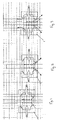
- the valve comprises a valve body 1 having an least one EGR inlet 2 and at least one EGR outlet 3.
- a first or lower flow passage 10 extends on opposite sides of a first or lower valve seat 12.
- a first or lower pintle valve 14 is reciprocable on a valve axis within the valve body 1 between a first position wherein the first pintle valve 14 engages the first valve seat 12 to close fluid communication through the first flow passage 10 and a second position wherein the first pintle valve 14 is spaced from the first valve seat 12 to permit EGR gases to flow through the first flow passage 10.
- a second or upper flow passage 20 extends on opposite sides of a second or upper valve seat 22.
- a second or upper pintle valve 24 is reciprocable on the valve axis, coaxially with the first pintle valve 14, within the valve body 1 between a second position wherein the second pintle valve 24 engages the second valve seat 22 to close fluid communication through the second flow passage 20 and a second position wherein the second pintle valve 24 is spaced from the second valve seat 22 to permit EGR gases to flow through the second flow passage 20.
- a pintle shaft 30 extends from the first pintle valve 14 and is connected to an armature of a solenoid (not shown) for actuating the EGR valve.
- the second pintle valve 24 is slidably mounted on the pintle shaft 30.
- the pintle shaft 30 comprises a first diameter portion 32, extending from the first pintle valve 14 and through the second pintle valve 24, the second pintle valve being axially slidable upon said first portion 32 of the pintle shaft 30, and a second diameter portion 34, said second diameter portion 34 being of greater diameter than the first diameter portion 32 and defining a shoulder 36 between said first and second portions, said shoulder being adapted to abut the second pintle valve 24 to open the second pintle valve 24 as will be described below.
- a compression spring 40 is located between the first and second pintle valves 14,24 to bias the second pintle valve 24 towards the second valve seat 22.
- the solenoid is actuated (or alternatively a spring biasing member is provided) to hold the first pintle valve 14 against the first valve seat 12.
- the shoulder 36 is spaced from the second pintle valve 24 and thus the second pintle valve is held against the second valve seat 22 by the spring 40.
- the first pintle valve 14 and first valve seat 12 is smaller in diameter than the second pintle valve 24 and second valve seat 22.
- the solenoid When a low EGR flow rate is required, the solenoid is actuated to move the pintle shaft 30 and the associated first pintle valve 14 to a second or low flow configuration, shown in Fig. 2, whereby EGR gases can pass through the first flow passage.
- the shoulder 36 remains spaced from the second pintle valve 24 such that the second pintle valve 24 remains in contact with the second valve seat 22 under the action of the spring 40.
- the solenoid is further actuated to move the pintle shaft 30 to a third or high flow configuration wherein the first pintle valve 14 is further spaced from the first valve seat 12.
- the shoulder 36 of the pintle shaft 30 abuts the second valve seat and pushes the second pintle valve 24 away from the second valve seat 22, as shown in Fig. 3, whereby EGR gases can pass through both the first and second flow passages.
- first pintle valve 14 and first flow passage 10 are used. Because of the relatively small diameter of the first pintle valve 14 and first valve seat 12, the change in flow rate for a given stroke of the pintle shaft 30 is small, allowing accurate control of the flow rate.
- both the first and second pintle valves 14,24 and first and second flow passages 10,20 are used, allowing greater flow for a given pintle shaft 30 stroke than when only the first pintle valve 14 is used in the low flow configuration.
Landscapes
- Engineering & Computer Science (AREA)
- General Engineering & Computer Science (AREA)
- Mechanical Engineering (AREA)
- Chemical & Material Sciences (AREA)
- Combustion & Propulsion (AREA)
- Exhaust-Gas Circulating Devices (AREA)
- Lift Valve (AREA)
Priority Applications (1)
| Application Number | Priority Date | Filing Date | Title |
|---|---|---|---|
| EP06250024A EP1806496A1 (fr) | 2006-01-04 | 2006-01-04 | Vanne pour commander le recyclage des gaz d'échappement dans un moteur |
Applications Claiming Priority (1)
| Application Number | Priority Date | Filing Date | Title |
|---|---|---|---|
| EP06250024A EP1806496A1 (fr) | 2006-01-04 | 2006-01-04 | Vanne pour commander le recyclage des gaz d'échappement dans un moteur |
Publications (1)
| Publication Number | Publication Date |
|---|---|
| EP1806496A1 true EP1806496A1 (fr) | 2007-07-11 |
Family
ID=36441297
Family Applications (1)
| Application Number | Title | Priority Date | Filing Date |
|---|---|---|---|
| EP06250024A Withdrawn EP1806496A1 (fr) | 2006-01-04 | 2006-01-04 | Vanne pour commander le recyclage des gaz d'échappement dans un moteur |
Country Status (1)
| Country | Link |
|---|---|
| EP (1) | EP1806496A1 (fr) |
Citations (7)
| Publication number | Priority date | Publication date | Assignee | Title |
|---|---|---|---|---|
| US5927257A (en) * | 1997-09-19 | 1999-07-27 | Caterpillar Inc | Pressure compensating exhaust gas recirculation valve |
| US6006732A (en) * | 1998-09-03 | 1999-12-28 | Navistar International Transportation Corp | Balanced flow EGR control apparatus |
| DE19942329A1 (de) * | 1998-03-07 | 2001-03-08 | Mann & Hummel Filter | Vorrichtung zur Rückführung von Abgasen bei einem Verbrennungsmotor |
| EP1128055A2 (fr) * | 2000-02-22 | 2001-08-29 | Delphi Technologies, Inc. | Soupape de dosage à plusieurs étages à action étendue de dosage |
| US6390078B1 (en) * | 2000-04-18 | 2002-05-21 | Delphi Technologies, Inc. | Two stage concentric EGR valves |
| FR2827011A1 (fr) * | 2001-07-05 | 2003-01-10 | Renault | Vanne de commande pour un circuit de recirculation de gaz d'echappement d'un moteur a combustion interne |
| EP1275838A1 (fr) * | 2001-07-11 | 2003-01-15 | Cooper-Standard Automotive (Deutschland) GmbH | Système de recirculation de gaz d'échappement |
-
2006
- 2006-01-04 EP EP06250024A patent/EP1806496A1/fr not_active Withdrawn
Patent Citations (7)
| Publication number | Priority date | Publication date | Assignee | Title |
|---|---|---|---|---|
| US5927257A (en) * | 1997-09-19 | 1999-07-27 | Caterpillar Inc | Pressure compensating exhaust gas recirculation valve |
| DE19942329A1 (de) * | 1998-03-07 | 2001-03-08 | Mann & Hummel Filter | Vorrichtung zur Rückführung von Abgasen bei einem Verbrennungsmotor |
| US6006732A (en) * | 1998-09-03 | 1999-12-28 | Navistar International Transportation Corp | Balanced flow EGR control apparatus |
| EP1128055A2 (fr) * | 2000-02-22 | 2001-08-29 | Delphi Technologies, Inc. | Soupape de dosage à plusieurs étages à action étendue de dosage |
| US6390078B1 (en) * | 2000-04-18 | 2002-05-21 | Delphi Technologies, Inc. | Two stage concentric EGR valves |
| FR2827011A1 (fr) * | 2001-07-05 | 2003-01-10 | Renault | Vanne de commande pour un circuit de recirculation de gaz d'echappement d'un moteur a combustion interne |
| EP1275838A1 (fr) * | 2001-07-11 | 2003-01-15 | Cooper-Standard Automotive (Deutschland) GmbH | Système de recirculation de gaz d'échappement |
Similar Documents
| Publication | Publication Date | Title |
|---|---|---|
| EP1869308B1 (fr) | Soupape rge presentant une position de repos | |
| EP1270920A3 (fr) | Culbuteur pour soupape actionnée par came dans un système d'admission d'un moteur à combustion interne | |
| RU2371596C1 (ru) | Система регулирования смеси воздуха и рециркулирующих выхлопных газов (варианты) и способ регулирования смеси воздуха и рециркулирующих выхлопных газов в двигателе внутреннего сгорания | |
| US6886510B2 (en) | Engine valve actuator assembly with dual hydraulic feedback | |
| WO2003089819A1 (fr) | Soupape de commande des gaz d'echappement, dispositif et procede de commande de l'ecoulement des gaz d'echappement | |
| US7461642B2 (en) | Rotary-actuated exhaust gas recirculation valve having a seating force attenuator | |
| CN102345537B (zh) | 废气再循环(egr)设备 | |
| EP1640599B1 (fr) | Système de recirculation de gaz d'échappement pour un moteur à combustion interne | |
| US6390078B1 (en) | Two stage concentric EGR valves | |
| JP2008115868A (ja) | エンジン排気ガス再循環(egr)弁 | |
| WO2006092401A1 (fr) | Dérivation et vanne integrée à recirculation des gaz d’échappement | |
| US7204240B2 (en) | Integrated valve | |
| EP1806496A1 (fr) | Vanne pour commander le recyclage des gaz d'échappement dans un moteur | |
| US8746279B2 (en) | Pressure control valve | |
| US6959673B2 (en) | Engine valve actuator assembly with dual automatic regulation | |
| EP3633179B1 (fr) | Système de recirculation des gaz d'échappement dans un véhicule | |
| US6918360B2 (en) | Engine valve actuator assembly with hydraulic feedback | |
| JPH10513243A (ja) | 内燃機関のためのシリンダーヘッドにおける装置 | |
| EP1136688A3 (fr) | Dispositif de recirculation de gaz d'échappement pour un moteur à combustion interne | |
| JPH11200959A (ja) | Egrバルブ構造 | |
| US20060081228A1 (en) | Exhaust gas recirculation valve and poppet | |
| GB2501710A (en) | Exhaust gas recirculation valve with fluid deflector | |
| JPH01177409A (ja) | エンジンの吸気装置 | |
| EP1739301A1 (fr) | Soupape de recirculation de gaz d'échappement pour un moteur à combustion interne et son siège de soupape | |
| KR101294496B1 (ko) | 차량의 배기가스 재순환밸브 |
Legal Events
| Date | Code | Title | Description |
|---|---|---|---|
| PUAI | Public reference made under article 153(3) epc to a published international application that has entered the european phase |
Free format text: ORIGINAL CODE: 0009012 |
|
| AK | Designated contracting states |
Kind code of ref document: A1 Designated state(s): AT BE BG CH CY CZ DE DK EE ES FI FR GB GR HU IE IS IT LI LT LU LV MC NL PL PT RO SE SI SK TR |
|
| AX | Request for extension of the european patent |
Extension state: AL BA HR MK YU |
|
| AKX | Designation fees paid | ||
| REG | Reference to a national code |
Ref country code: DE Ref legal event code: 8566 |
|
| STAA | Information on the status of an ep patent application or granted ep patent |
Free format text: STATUS: THE APPLICATION IS DEEMED TO BE WITHDRAWN |
|
| 18D | Application deemed to be withdrawn |
Effective date: 20080112 |