EP1806528B1 - Raccord pour tuyaux avec embouts - Google Patents
Raccord pour tuyaux avec embouts Download PDFInfo
- Publication number
- EP1806528B1 EP1806528B1 EP06000154A EP06000154A EP1806528B1 EP 1806528 B1 EP1806528 B1 EP 1806528B1 EP 06000154 A EP06000154 A EP 06000154A EP 06000154 A EP06000154 A EP 06000154A EP 1806528 B1 EP1806528 B1 EP 1806528B1
- Authority
- EP
- European Patent Office
- Prior art keywords
- spring band
- arrangement according
- flanges
- connecting arrangement
- radial
- Prior art date
- Legal status (The legal status is an assumption and is not a legal conclusion. Google has not performed a legal analysis and makes no representation as to the accuracy of the status listed.)
- Expired - Lifetime
Links
Images




Classifications
-
- F—MECHANICAL ENGINEERING; LIGHTING; HEATING; WEAPONS; BLASTING
- F16—ENGINEERING ELEMENTS AND UNITS; GENERAL MEASURES FOR PRODUCING AND MAINTAINING EFFECTIVE FUNCTIONING OF MACHINES OR INSTALLATIONS; THERMAL INSULATION IN GENERAL
- F16L—PIPES; JOINTS OR FITTINGS FOR PIPES; SUPPORTS FOR PIPES, CABLES OR PROTECTIVE TUBING; MEANS FOR THERMAL INSULATION IN GENERAL
- F16L37/00—Couplings of the quick-acting type
- F16L37/08—Couplings of the quick-acting type in which the connection between abutting or axially overlapping ends is maintained by locking members
- F16L37/12—Couplings of the quick-acting type in which the connection between abutting or axially overlapping ends is maintained by locking members using hooks, pawls, or other movable or insertable locking members
- F16L37/1225—Couplings of the quick-acting type in which the connection between abutting or axially overlapping ends is maintained by locking members using hooks, pawls, or other movable or insertable locking members using a retaining member the extremities of which, e.g. in the form of a U, engage behind a shoulder of both parts
-
- F—MECHANICAL ENGINEERING; LIGHTING; HEATING; WEAPONS; BLASTING
- F16—ENGINEERING ELEMENTS AND UNITS; GENERAL MEASURES FOR PRODUCING AND MAINTAINING EFFECTIVE FUNCTIONING OF MACHINES OR INSTALLATIONS; THERMAL INSULATION IN GENERAL
- F16L—PIPES; JOINTS OR FITTINGS FOR PIPES; SUPPORTS FOR PIPES, CABLES OR PROTECTIVE TUBING; MEANS FOR THERMAL INSULATION IN GENERAL
- F16L21/00—Joints with sleeve or socket
-
- F—MECHANICAL ENGINEERING; LIGHTING; HEATING; WEAPONS; BLASTING
- F16—ENGINEERING ELEMENTS AND UNITS; GENERAL MEASURES FOR PRODUCING AND MAINTAINING EFFECTIVE FUNCTIONING OF MACHINES OR INSTALLATIONS; THERMAL INSULATION IN GENERAL
- F16L—PIPES; JOINTS OR FITTINGS FOR PIPES; SUPPORTS FOR PIPES, CABLES OR PROTECTIVE TUBING; MEANS FOR THERMAL INSULATION IN GENERAL
- F16L33/00—Arrangements for connecting hoses to rigid members; Rigid hose-connectors, i.e. single members engaging both hoses
- F16L33/02—Hose-clips
- F16L33/03—Self-locking elastic clips
-
- F—MECHANICAL ENGINEERING; LIGHTING; HEATING; WEAPONS; BLASTING
- F16—ENGINEERING ELEMENTS AND UNITS; GENERAL MEASURES FOR PRODUCING AND MAINTAINING EFFECTIVE FUNCTIONING OF MACHINES OR INSTALLATIONS; THERMAL INSULATION IN GENERAL
- F16L—PIPES; JOINTS OR FITTINGS FOR PIPES; SUPPORTS FOR PIPES, CABLES OR PROTECTIVE TUBING; MEANS FOR THERMAL INSULATION IN GENERAL
- F16L33/00—Arrangements for connecting hoses to rigid members; Rigid hose-connectors, i.e. single members engaging both hoses
- F16L33/02—Hose-clips
- F16L33/08—Hose-clips in which a worm coacts with a part of the hose-encircling member that is toothed like a worm-wheel
-
- F—MECHANICAL ENGINEERING; LIGHTING; HEATING; WEAPONS; BLASTING
- F16—ENGINEERING ELEMENTS AND UNITS; GENERAL MEASURES FOR PRODUCING AND MAINTAINING EFFECTIVE FUNCTIONING OF MACHINES OR INSTALLATIONS; THERMAL INSULATION IN GENERAL
- F16L—PIPES; JOINTS OR FITTINGS FOR PIPES; SUPPORTS FOR PIPES, CABLES OR PROTECTIVE TUBING; MEANS FOR THERMAL INSULATION IN GENERAL
- F16L37/00—Couplings of the quick-acting type
-
- F—MECHANICAL ENGINEERING; LIGHTING; HEATING; WEAPONS; BLASTING
- F16—ENGINEERING ELEMENTS AND UNITS; GENERAL MEASURES FOR PRODUCING AND MAINTAINING EFFECTIVE FUNCTIONING OF MACHINES OR INSTALLATIONS; THERMAL INSULATION IN GENERAL
- F16L—PIPES; JOINTS OR FITTINGS FOR PIPES; SUPPORTS FOR PIPES, CABLES OR PROTECTIVE TUBING; MEANS FOR THERMAL INSULATION IN GENERAL
- F16L37/00—Couplings of the quick-acting type
- F16L37/08—Couplings of the quick-acting type in which the connection between abutting or axially overlapping ends is maintained by locking members
- F16L37/084—Couplings of the quick-acting type in which the connection between abutting or axially overlapping ends is maintained by locking members combined with automatic locking
- F16L37/098—Couplings of the quick-acting type in which the connection between abutting or axially overlapping ends is maintained by locking members combined with automatic locking by means of flexible hooks
- F16L37/0985—Couplings of the quick-acting type in which the connection between abutting or axially overlapping ends is maintained by locking members combined with automatic locking by means of flexible hooks the flexible hook extending radially inwardly from an outer part and engaging a bead, recess or the like on an inner part
- F16L37/0987—Couplings of the quick-acting type in which the connection between abutting or axially overlapping ends is maintained by locking members combined with automatic locking by means of flexible hooks the flexible hook extending radially inwardly from an outer part and engaging a bead, recess or the like on an inner part the flexible hook being progressively compressed by axial tensile loads acting on the coupling
Definitions
- the invention relates to a connection arrangement with pipe socket to be connected fluid receiving parts, such as fluid lines and containers
- the pipe sockets are each provided with a coaxial to its central axis retaining rib, behind which a groove is formed and a central axis coaxial, conical leading edge and a radial trailing edge, wherein the leading edge of a retaining rib opposite the leading edge of the other retaining rib and the trailing edge of at least one retaining rib which forms a wall of the adjacent groove, and with a more than 240 ° substantially circularly curved spring steel strip whose axial ends have inwardly directed flanges with largely circular arc-shaped, coaxial with the central axis inner edge, which engage behind the retaining ribs and at least on the Circumferential ends of the spring band opposite side of the spring band are interrupted, and wherein the pipe socket are partially inserted into one another and the nested parts of the pipe socket are sealed by at least one sealing ring against each other.
- the invention relates to a connection arrangement with pipe socket to be connected fluid receiving parts, such as fluid lines or containers
- the pipe sockets are each provided with a coaxial to its central axis retaining rib with radial trailing edge, the trailing edge of at least one of the retaining ribs defining a groove, and with a over at least 240 ° substantially circular curved spring steel strip whose axial ends have inwardly directed flanges with a substantially arcuate, coaxial to the central axis inner edge, which engage behind the retaining ribs and at least on the circumferential ends of the spring band opposite side of the spring band are interrupted, and wherein the pipe sockets are partially inserted into one another and the nested parts of the pipe socket are sealed against each other by at least one sealing ring.
- the spring band is placed radially widening on the holding ribs of the pipe socket.
- the pipe socket can not be inserted axially, as in a plug-in coupling, in the spring band, because it moves one of the flanges axially in the groove behind the one retaining rib until the other flange abuts against this retaining rib and no more free space for receiving the other retaining rib between the flanges remains.
- connection arrangements with a spring band for example that of the DE 198 18 562 C1 or the DE 198 00 283 C1 known spring band, a so-called “profile clamp", are used for connecting pipes, which are provided at their ends with holding ribs in the form of flanges whose ends facing away from the flanks are conical.
- the spring band is made of sheet steel. Its lateral edges are bent inward to form the flanges at an angle of less than 90 °. The angle corresponds to the cone angle of the flanges at the pipe ends.
- a slot between the ends of the spring band can be bridged by a latch or joint closure.
- the slot opposite the hinge is formed by the material of the spring band in the region of an interruption of the flanges of the spring band in the manner of a "film hinge” or by another joint closure.
- the spring band is placed around the flanges of the tubes with the closure (or open caps) open, and the or each closure is closed again.
- the steel sheet of the spring band is indeed in the version with "film joint” ( DE 198 18 562 C1 ) in the region of the joint flexible, but does not exert a radial clamping force on the tubes.
- the clamping force is based solely on the clamping force of the closure or the closures.
- a connection arrangement with a profile clamp is therefore not suitable as an easy-to-close plug-in coupling, in which the Tube ends need only be inserted axially into the profile clamp and the flanges when inserting behind the retaining ribs on the tubes engage to make the connection.
- the production of the spring band with a locking closure which is formed integrally with the spring band, requires complex punching and bending tools.
- the production of the spring band with a joint closure additionally requires its training and installation.
- the coupling In a plug-in, as they are from the EP 1 378 701 A1 is known, the coupling consists of elastic plastic. It has two oval rings, which are connected by two diametrically opposed webs. The rings are provided with locking lugs inside. When inserting the pipe ends in the rings, the rings are elastically expanded by holding ribs on end portions of the tubes until the locking lugs of the rings engage behind the retaining ribs. In the engaged state remains between the annular areas with the smaller radius of curvature and the pipes a margin that allows a radial interaction of the rings for uncoupling. The material of this coupling is limited to plastic. For the preparation of the coupling a complex mold is required. Because of the wide spaces between the lands and the decoupling clearance between the rings and the tubes, there is a possibility that the end portions of the tubes introduced into the coupling become soiled. This can make repeated engagement and disengagement difficult.
- CH 379854 is described a butt joint for connecting a corrugated pipe with another pipe.
- Butt joint are provided inwardly directed, wavy tongues. These tongues form teeth that engage in the troughs of a corrugated hose.
- the invention has for its object to provide a connection arrangement of the aforementioned types, which is easier to handle and manufacture and is more resistant.
- a first solution to this problem according to the invention is that the leading edges of the retaining ribs with the central axis include a smaller angle than 50 °, that the radius of the smallest circumference of the leading edges of the retaining ribs is smaller than the inner radius of the flanges of the spring band, that the axial width of the Flanges the width of the receiving groove corresponds and that the spring band is corrosion resistant.
- a second solution to this problem according to the invention is that the flanges of the spring band each have a radially inwardly and an obliquely outwardly bent portion that the oblique portion with the central axis of the respective pipe socket forms an angle in the range of 10 ° to 60 °, that the diameter of the inner edge of the outer edge of the oblique portion is greater than the smallest outer diameter of the retaining ribs, that the axial width of at least one flange corresponds to the width of the groove receiving it and that the spring band is corrosion resistant.
- connection assembly can be handled easily as a plug-in coupling to connect the pipe socket and associated fluid receiving parts, such as fluid lines and fluid reservoir, in particular fuel tanks and radiator of motor vehicles.
- the spring band can be preassembled on one of the pipe socket.
- the spring band is not only corrosion resistant, but also heat resistant, so that the Connection arrangement is also suitable for pipelines, such as exhaust pipes, through which a very hot fluid is passed.
- the holding ribs on the pipe socket While in the first solution the holding ribs on the pipe socket have a conical leading edge, the leading edge of at least one of the holding ribs in the second solution can be radial. Accordingly, the retaining ribs can be made very narrow, so that the spring band can be correspondingly narrower and less material consuming.
- an embodiment may be that the flanges provided at the one axial end of the spring band are shorter in the circumferential direction of the spring band than the flanges provided at the other end of the spring band. This facilitates the uncoupling of a pipe socket, since the spring band for uncoupling needs to be spread or widened only so far until a pipe socket between the flanges at one axial end of the spring band can be pulled out while the flanges at the other axial end of the spring band Continue to remain locked behind the retaining rib of the other pipe socket.
- the flanges provided at the one axial end of the spring band are narrower in the radial direction than the flanges provided at the other end of the spring band.
- At least one axial end of the spring band at least one of the flanges is provided with a radial cut-out for introducing a respective radial projection on the inserted into this end pipe socket.
- the circumferential ends of the spring band can define an axial slot with a width of 0 to 2 mm. This allows the introduction of a simple spreading tool, e.g. the blade of a screwdriver to spread or expand the spring band sufficiently for uncoupling at least one pipe socket.
- the circumferential ends of the spring band may be provided with recesses for insertion of a spreading tool, e.g. a spreader forceps, be provided.
- a spreading tool e.g. a spreader forceps
- the recesses adjacent circumferential end portions of the spring band may be provided with holes for insertion of a spreading tool the slot.
- the peripheral end portions of the spring band may further each be provided with a directed away from the outside of the spring band projection for attaching a spreading tool.
- projections can be formed in a simple manner by bent peripheral end portions of the spring band.
- peripheral end portions of the spring band may be radial, planar or angled spreader jaws or high-cylinder.
- covers made of plastic may be attached to the outside of peripheral end portions of the spring band. These covers protect the spring band, especially when it is provided with a corrosion-resistant protective layer, from impact loads, such as rockfall in the engine compartment or exhaust gas of a motor vehicle.
- the covers can be attached in a simple manner positively to the calculatorsendabroughen the spring band.
- This type of attachment can be achieved in that radial projections of the covers are engaged in holes of the peripheral end portions of the spring band.
- covers can cover the flanges of the spring band with radial flanges to protect the flanges from shock loads.
- the one pipe socket is surrounded by a sleeve having an axial, peripheral end portions of the spring band releasing slot in a radial, the maximum required spread width of the spring band corresponding distance.
- This sleeve not only provides protection of the spring band and possibly additionally provided cover, but also for a Aufsp Dretzbegrenzung the spring band, so as not to spread or widen excessively, especially not so far that both pipe sockets can be decoupled, if only a pipe socket uncoupled and the spring band should remain mounted on the other pipe socket.
- the sleeve can be attached in a snap-fit radially on the one pipe socket in a snap fit. It can then not only be fixed from the outset on the one pipe socket, but also be attached later.
- the flanges can enclose an angle in the range of 15 ° to 90 ° with the region of the spring band which connects them axially.
- An angle of 90 ° has the advantage that the distance of the retaining ribs from an opposite Groove or housing wall can be kept less than at an angle of less than 90 °, which means that the spring band narrower and the pipe socket can be made correspondingly shorter than at an angle of less than 90 °.
- a smaller angle than 90 ° has the advantage that the flanges provide a higher rigidity or a greater resistance to axial bending under axial load of the spring band by the fluid pressure in the interior of the pipe socket.
- the spring band may be connected by a web to a hose clamp for clamping a fluid line on one of the pipe sockets. This has the advantage that the spring band can simultaneously serve for pre-assembly of the hose clamp on the pipe socket before the fluid line is clamped with the hose clamp on the pipe socket.
- the spring band may be connected by a web with a serving for clamping a fluid line on one of the pipe sockets hose clamp.
- connection arrangement with pipe socket of fluid receiving parts to be connected, such as fluid lines and containers, wherein the pipe sockets are each provided with a coaxial to its central axis holding rib with radial trailing edge, wherein
- the trailing edge of at least one of the retaining ribs delimits a groove, and with a spring band made of steel bent over at least 240 °, which has inwardly directed projections with radial surfaces which bear against the trailing edges of the retaining ribs, the projections as latching noses pressed out of the spring band form, wherein the spring band is corrosion resistant.
- These locking lugs can be formed particularly rigid, especially if they are each pushed out at one edge of limited in their length peripheral slots.
- peripheral slots are slots each with a directed in the flat state of the spring band transversely to the slot tab whose edge forms in the pressed out of the spring band state of the projection, the radial surface for engagement with the trailing edge in each case one of the retaining ribs ,
- the pipe sockets are preferably plastic. They can therefore be easily formed. By appropriate reinforcing additives, such as glass fibers, they can withstand high forces, in particular shear forces in the region of the holding ribs.
- connection arrangement is electrically conductive throughout the existing metal spring band to avoid electrostatic charging, which is particularly advantageous if the Fluid receiving parts, such as fluid lines or fluid container, are electrically conductive.
- connection arrangement consists of two partially nested pipe socket 1 and 2, a pipe socket 1 and 2 connecting spring band 3, a sleeve 4 and two sealing rings. 5
- the pipe sockets comprise thermoplastic material with reinforcing material, such as glass fibers, and an electrically conductive additive.
- the pipe socket 2 consists of two parts 6 and 7, which are positively connected to each other and by a fusion bond.
- the part 6 forms a diffusion barrier, which is preferably formed by a polyamide.
- the part 7 contains polyethylene, which does not form a diffusion barrier, but can be fused with a corresponding material, such as high-density polyethylene of a fuel tank. In order to connect the pipe socket 2 with the fuel tank, the part 7 is fused with the edge of the filling opening of the fuel tank.
- the spring band 3 is made of metal, such as spring steel, and is corrosion resistant. For this purpose, it may consist of either corrosion-resistant, in particular stainless steel or of metal which is coated with a corrosion-resistant material.
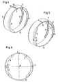
- the spring band 3 has at its axial ends radially inwardly bent flanges 8, as in Fig. 4
- the edges of the axial slot or the circumferential ends of the spring band 3 are provided with opposite recesses 10 for introducing a (not shown) spreading tool, here a spreading pliers.
- a spreading tool here a spreading pliers.
- the flanges are interrupted, so that the spring band 3 forms a resilient joint 11 in this area.
- the stubs 1 and 2 are each provided with a to its central axis M coaxial retaining rib 12, behind which a circumferential groove 13 is formed and which has a coaxial to the central axis M, conical leading edge 14 and a radial trailing edge 15.
- the pipe sockets 1, 2 and thus associated with them fluid receiving parts are connected in such a way that initially one of the pipe socket 1, 2 with its conical edge 14 ahead under the flanges 8 at one axial end, under spreading of the spring band, so far is introduced into this until these flanges 8 are engaged behind the retaining rib 2 by the spring force of the spring band 3 in the groove 13. Thereafter, the other of the two pipe sockets 1, 2 with the leading edge 14 of its retaining rib 12 ahead with renewed spreading of the spring band 3 so far introduced into the spring band 3 until the provided at the other axial end of the spring band 3 flanges 8 are engaged behind this retaining rib 12 in the groove 13.
- the width of the grooves 13 corresponds approximately to the axial width of the flanges 8.
- the spring band 3 while the pipe socket 1, 2 are plugged together under the spring band 3, not axially displaced by the leading edge 14 of the retaining rib 12 of the last inserted pipe socket 1 or 2 become.
- the leading edges 14 of the retaining ribs 12 are close to each other, so that the spring band 3 in the axial direction is relatively narrow and only slightly wider than the total width of both retaining ribs 12.
- the leading edges 14 of the holding ribs close to the central axis M or longitudinal direction of the pipe socket an angle ⁇ , which is smaller than 50 °, so that the pipe socket 1, 2 can be easily inserted into the spring band 3.
- the radius of the smallest circumference of the leading edges 14 of the retaining ribs 12 is smaller than the inner radius of the flanges 8 of the spring band 3, so that the leading edges 14 coincide when mating the tubes 1, 2 with the radially inner edges of the flanges 8 and these edges the leading edges 14 can slide radially outward.
- the sleeve 4 also has a (not shown) axially continuous slot and is resilient, and it may consist of spring steel or plastic. It is on an at least partially encircling, the groove 13 limiting flange 16 radially snapped, wherein it wraps around the flange 16 by a little more than 180 °. At the same time, the sleeve 4 serves to limit the maximum Aufsp Schwarzweges of the spring band 3, thereby simultaneously ensuring that the spring band 3 is widened symmetrically with respect to the central axis M.
- Fig. 4 extend the flanges 8 in the circumferential direction only so far that the spring band 3 only needs to be spread so far for uncoupling or separating the pipe socket 1, 2 that the retaining ribs 12 can be pulled out just below the flanges 8 away from the spring band 3.
- the pipe socket 1 If it is desired to uncouple only one pipe socket, for example, the pipe socket 1, and to leave the spring band 3 preassembled on the other pipe socket, for example, the outer diameter of the retaining rib 12 of that pipe socket, for example, the pipe socket 2 on which the spring band 3 remain pre-assembled should, slightly larger than the outer diameter of the retaining rib 12 of the other pipe socket (or the outer diameter of the retaining rib 12 of the pipe socket 1 smaller than the outer diameter of the retaining rib 12 of the pipe socket 2) are selected, as shown in Fig. 2 is shown, so that only a pipe socket, here the pipe socket 1, can be decoupled by correspondingly small spreading of the spring band 3.
- the same function can also be achieved in that with retaining ribs 12 with the same outer diameters, the flanges 8 radially shorter (with a lower radial height), for example, the in Fig. 3 Flanges 8 shown on the left, as the other flanges 8 are selected.
- the shorter in the circumferential direction flanges 8 therefore extend in its groove 13 only over a smaller wrap angle, so that they disengage when spreading the spring band 3 to the pipe socket 1, 2, first disengage behind this groove 13 limiting retaining rib 12 and the relevant Pipe stub can be decoupled alone if the spring band 3 is not spread further.
- the flanges 8 or only one of the flanges formed at the one axial end of the spring band 3 can be provided with a narrow radial cutout 17 into each of which a radial projection (not shown) can be introduced at the pipe socket inserted into this end ,
- the spring band 3 after Fig. 7 is different from that Fig. 4 in that all the flanges 8 are provided with a recess 17 into each of which a radial projection can be inserted at the inserted into this end pipe socket to mount the spring band 3 relative to both pipe sockets 1, 2 in a predetermined angular position.
- radially through holes 18 are formed in the vicinity of the circumferential ends of the spring band 3, which serve for the introduction of a spreading tool, for example a spreading forceps.
- the at the spring band 3 after Fig. 4 provided recesses 10 are therefore eliminated. Nevertheless, the circumferential ends of the spring band 3 in the engaged state of the pipe socket 1, 2 may be separated according to the width of the slot.
- the spring band 3 may be sized so that its peripheral ends in the engaged state of the pipe socket 1, 2 abut each other and the spring band 3, the pipe socket 1, 2 firmly encloses.
- the spring band 3 after Fig. 8 is different from that Fig. 4 in that end portions of the spring band 3 overlap in the engaged state of the pipe socket 1, 2 and are also provided with holes 18 for the introduction of a spreading tool.
- the overlap serves to not pinch a portion of the hand in the slot 9 provided in the above-described spring bands when engaging or disengaging the pipe socket 1, 2.
- the spring band 3, regardless of different dimensional tolerances completely cover the sealing gap between the pipe socket with greater security to prevent the ingress of dirt and flames in case of fire.
- the spring band 3 after Fig. 9 is different from that Fig. 8 only in that the outer end portion of the spring band has a bend 19 corresponding to the thickness of the spring band 3. This bend 19 prevents that with greater certainty no gap between the overlapping end portions is formed when the spring band contracts.
- the overlap after the 8 and 9 may also be provided in the above-described and below described spring bands 3.
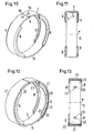
- the spring band 3 after the 10 and 11 is different from that Fig. 7 in that the flanges 8 on both sides of the joint 11 and the slot 9 are not interrupted, but with the flanges 8 connecting axially central region of the spring band 3 include an angle ⁇ , which is smaller than the 90 ° angle of the above and described below
- Spring bands 3 is and in the range of 15 ° to 85 °, preferably from 15 ° to 75 °. Shown is an angle ⁇ of 75 °.
- the angle ⁇ not only facilitates the insertion of the pipe socket 1, 2 in the spring band 3, but also increases the rigidity of the flanges 8 against bending under the internal pressure of the connection assembly.
- the compensatesendabroughe 20 of the spring band 3 each having a directed away from the outside of the spring band 3 projection 27 and 28 to the extends Applying a spreading tool provided.
- These projections 27, 28 are formed by bending the ends of the peripheral end portions of the spring band 3.
- the projection 27 provided with a bent at one end of the slot 26 tongue 29 which abuts the projection 28 in the maximum Aufsp Sanderslage the spring band 3 and thus limits the Aufsp Sonweg.
- the spring band 3 corresponds, except for the flanges 8, a conventional spring band clamp and can therefore be made in the same way as this with similar tools and of the same material.
- results from the extending into the slot 26 tail 25 also overlap the calculatorsendabroughe 20 in a similar manner as in the spring bands 3 after the 8 and 9 ,
- the projections 27 and 28 act in the same manner as in a conventional spring band clip as expanding jaws.
- the spring band 3 after Fig. 17 is different from that Fig. 16 in that the free ends of the spring band are largely bent back to largely hollow cylindrical projections 30, 31 on the end portions 20 and also serve as expansion jaws for applying a spreading tool either between the projections 30, 31 or in their cavities. They therefore act equally as expanding jaws.
- the projections 27 and 28 in the spring band 3 after Fig. 16 can as well as hollow cylindrical as the projections 30, 31 in the spring band after Fig. 17 be bent, with the end piece 25 of the spring band after Fig. 16 can continue to extend through the slot 26.
- connection arrangement is the preassembled on the pipe socket 1 spring band 3, which is designed as well as the spring band 3 after Fig. 10 but with an angle ⁇ according to Fig. 11 of 90 °, connected by a integrally formed with the spring band 3 web 32 with a conventional hose clamp 33, here a worm thread clamp, through which a fluid line 34 is connected in the form of an elastic plastic or rubber hose with the pipe socket 1.
- the connection between the web 32 and the clamping band 35 of the hose clamp 33 may be a welded connection, eg spot welding connection, or a positive connection.
- the fluid line 34 is pushed with the hose clamp 33 still open on the ribbed end portion of the pipe socket 1 and then clamped the hose clamp 33 so that they Clamp fluid line 34 on the pipe socket.
- This design has the advantage that the spring band 3 and the hose clamp 33 can be supplied preassembled on the pipe socket 1 for final assembly to a car manufacturer, where then the final assembly by mating the pipe socket 1, 2 and the connection of the fluid line can be performed in a simple manner ,
- FIGS. 22 to 25 shown parts of the connection arrangement according to those in the Fig. 18 to 21 shown, only that a conventional spring band clamp 36 is provided as a hose clamp and the spring band 3 is integrally connected to the hose clamp 36 through the web 32.
- This training has the Advantage that the spring band 3 and the spring band clamp 36 can be made in one piece and of the same material.
- worm thread clamp or spring band clamp can also be a crimp sleeve connected as a hose clamp with the spring band 3 through the web 32.
- connection arrangement largely corresponds to in Fig. 1 shown, only that the pipe socket 1 is provided with a substantially rectangular in cross-section retaining rib 37 and has no annular grooves for receiving the sealing rings 5, that the retaining rib 12 extends beyond the free end of the inserted into the pipe socket 2 part of the pipe socket 1 out and on its inside with the sealing rings 5 receiving annular grooves is provided and that the flanges 8 of the spring band 3 have a radially inwardly bent portion 38 and an obliquely outwardly bent portion 39, wherein the inclined portion 39 with the central axis M of the respective pipe socket 1, 2 an angle ⁇ in the range of 10 ° to 60 ° and the diameter of the radially inner edges of the radially outer edges of the inclined portions 39 is greater than that of the retaining rib 37 and the smallest diameter of the leading edge 14 of the retaining rib 12.
- the axial width of at least one flange 8, here both flanges 8 still corresponds to the width
- This design has the advantage that the flanges 8 of the spring band 3 when mating the pipe ends 1, 2 do not slide over the sealing rings 5, but also the cooperating with the sealing rings 5 sealing surface of the pipe socket 1 when mating the pipe socket 1, 2 are not largely damaged by the radially inner edges of the flanges 8, because these edges are largely round and not sharp.
- the radially inner edges of the radially outer edges of the inclined portions 39 have a larger diameter than on the one hand, the retaining rib 37 and the other the smallest perimeter of the leading edge 14 of the retaining rib 12.
- the oblique portions 39 therefore slide when Georgianadjustken the pipe socket 1, 2 on the one hand over the flank 14 facing away from the edge of the retaining rib 37 and on the other hand over the retaining rib 37 facing radially inner edge of the leading edge 14 easily away.
- the inclined portions 39 are conical.
- connection arrangement according to Fig. 28 is different from the one after the FIGS. 26 and 27 only in that the in the FIGS. 26 and 27 groove 13 shown on the right, as well as in the connection arrangement according to Fig. 1 , in addition to an axially shorter retaining rib 12 of the pipe socket 2 and only as deep as the grooves 13 after Fig. 1 is formed so that the clamping band 3 of the connection arrangement according to Fig. 28 much narrower than the tension band 3 of the connection arrangement according to the FIGS. 26 and 27 can be trained.
- Fig. 29 represents a spring band 3, compared to the after the FIGS. 26 to 28 is modified insofar as the inclined portions 39 are rounded, so that the radially inner edge of the flanges 8 is rounded more.
- spring band 3 are pressed out instead of the flanges 8 radially inwardly directed projections 40 in the form of locking lugs from the calculatorsendabroughen 20 of the spring band 3 in two parallel radial planes near the axial ends of the spring band 3.
- the projections 40 are each pushed out at the one edge 41 of limited in their length circumferential slots 42 of the spring band 3.
- the circumferential slots 42 are slots each with a directed in the flat state of the spring band transversely to the slot tab, the edge of which forms in the pushed out of the spring band 3 state of the projection 40, a radial contact surface 43 for engagement with each one of the retaining ribs 44.
- the retaining ribs 44 can however also be approximately triangular with an oblique leading edge, like the leading edge 14 of the retaining ribs 12 Fig. 1 be trained.
- the projections 40 also have an inclined ramp surface 45, with which they slide over the radially outer, mutually facing edges of the retaining ribs 44 when inserting the pipe socket 1, 2 in the spring band 3 until they engage behind the trailing edges of the retaining ribs 44 in the grooves 13 ,
- the formation of the spring band 3 with the projections 40 has the advantage that the projections 40 withstand relatively high axial forces, which are caused by the internal pressure of the pipe socket 1, 2.
- the pressure of the contact surfaces 43 of the projections 40 acts practically only at the radially inner end of the trailing edges of the retaining ribs 44 on this, so that the retaining ribs 44 even with axially narrower training or training with an oblique leading edge on the radially outer edge are exposed to virtually no bending forces.
- the shape of the pipe socket 1, 2 with only two radially relatively short, the grooves 13 delimiting flanges 16 allows easy production of the pipe socket 1, 2 not only made of plastic, but also of metal.
- the width of the grooves 13 substantially corresponds to the axial width of the projections 40 including the width of radially short, outwardly directed stiffening flanges 46 at the axial ends of the spring band 3.
- the stiffening flanges 46 increase the flexural rigidity of the peripheral end portions 20, but leave the Edges of the elastically resilient joint 11 free.
- Variations of the illustrated embodiments may, for example, consist in that features of the individual embodiments are combined.
Landscapes
- Engineering & Computer Science (AREA)
- General Engineering & Computer Science (AREA)
- Mechanical Engineering (AREA)
- Quick-Acting Or Multi-Walled Pipe Joints (AREA)
- Joints With Sleeves (AREA)
- Clamps And Clips (AREA)
- Flanged Joints, Insulating Joints, And Other Joints (AREA)
Claims (23)
- Agencement de liaison comprenant des pipes tubulaires (1, 2) de pièces recevant du fluide qu'il s'agit de relier, comme des conduites (34) et des réservoirs à fluide, chaque pipe tubulaire (1, 2) étant pourvue d'une nervure de maintien (12), coaxiale à son axe médian (M), derrière laquelle est ménagée une gorge (13) et qui présente un flanc antérieur conique (14) coaxial à l'axe médian (M), et un flanc postérieur radial (15), le flanc antérieur (14) de l'une des nervures de maintien (12) étant opposé au flanc antérieur (14) de l'autre nervure de maintien (12) et le flanc postérieur (15) de l'une au moins des nervures de maintien (12) constituant l'une des parois de la gorge adjacente (13), et comprenant un ruban-ressort (3) en acier, cintré de manière largement circulaire sur plus de 240°, dont les extrémités axiales présentent des brides (8) dirigées vers l'intérieur avec une arête intérieure coaxiale à l'axe médian (M) et de forme largement circulaire, et qui s'engagent derrière les nervures de maintien (12) et étant interrompues au moins sur le côté du ruban-ressort (3) opposé aux extrémités périphériques du ruban-ressort (3) et les pipes tubulaires (1, 2) étant partiellement emboîtées l'une dans l'autre et les parties emboîtées l'une dans l'autre des pipes tubulaires (1, 2) étant étanchées l'une par rapport à l'autre par au moins une bague d'étanchéité (5), caractérisé en ce que les flancs antérieurs (14) des nervures de maintien (12) définissent avec l'axe médian (M) un angle (□) inférieur à 50°, en ce que le rayon du plus petit cercle entourant les flancs antérieurs (14) des nervures de maintien (12) est inférieur au rayon intérieur des brides (8) du ruban-ressort (3), en ce que la largeur axiale des brides (8) correspond à la largeur libre de la gorge (13) qui les reçoit, et en ce que le ruban-ressort (3) est résistant à la corrosion.
- Agencement de liaison comprenant des pipes tubulaires (1, 2) de pièces recevant du fluide qu'il s'agit de relier, comme des conduites (34) et des réservoirs à fluide, chaque pipe tubulaire (1, 2) étantt pourvue d'une nervure de maintien (12), coaxiale à son axe médian (M) avec un flanc postérieur radial (15), ledit flanc postérieur (15) de l'une au moins des nervures de maintien (12, 37) délimitant une gorge (13), et comprenant un ruban-ressort (3) en acier cintré largement en forme de cercle sur au moins 240°, dont les extrémités axiales présentent des brides (8) dirigées vers l'intérieur avec une arête intérieure coaxiale à l'axe médian (M) et de forme largement circulaire, et qui s'engagent derrière les nervures de maintien (12) et sont interrompues au moins sur le côté du ruban-ressort (3) opposé aux extrémités périphériques du ruban-ressort (3), et les pipes tubulaires (1, 2) étant partiellement emboîtées l'une dans l'autre et les parties emboîtées l'une dans l'autre des pipes tubulaires (1, 2) étant étanchées l'une par rapport à l'autre par au moins une bague d'étanchéité (5), caractérisé en ce que les brides (8) du ruban-ressort (3) possèdent chacune un tronçon cintré radialement vers l'intérieur et un tronçon cintré en oblique vers l'extérieur (38, 39), en ce que le tronçon oblique (39) définit avec l'axe médian (M) de la pipe tubulaire respective (1, 2) un angle (□) dans la plage de 10° à 60°, en ce que le diamètre de l'arête intérieure de la bordure extérieure du tronçon en oblique (39) est supérieur au plus petit diamètre extérieur des nervures de maintien (12, 37), en ce que la largeur axiale de l'une au moins des brides (8) correspond à la largeur libre de la gorge (13) qui la reçoit, et en ce que le ruban-ressort (3) est résistant à la corrosion.
- Agencement de liaison selon la revendication 2, caractérisé en ce que le flanc antérieur (14) de l'une au moins des nervures de maintien (12, 37) est radial.
- Agencement de liaison selon l'une des revendications 1 à 3, caractérisé en ce que la bride (8) prévue à une extrémité axiale du ruban-ressort (3) est plus courte, en direction périphérique du ruban-ressort (3), que la bride (8) prévue à l'autre extrémité du ruban-ressort (3).
- Agencement de liaison selon l'une des revendications 1 à 4, caractérisé en ce que la bride (8) prévue à l'une des extrémités axiales du ruban-ressort (3) est plus étroite en direction radiale que la bride (8) prévue à l'autre extrémité du ruban-ressort (3).
- Agencement de liaison selon l'une des revendications 1 à 5, caractérisé en ce que le diamètre extérieur de l'une des nervures de maintien (12) est supérieur à celui de l'autre nervure de maintien (12 ; 37).
- Agencement de liaison selon l'une des revendications 1 à 6, caractérisé en ce qu'au moins à une extrémité axiale du ruban-ressort (3) l'une au moins des brides (8) est pourvue d'une échancrure radiale (17) pour l'introduction d'une saillie radiale respective sur la pipe tubulaire (1 ; 2) introduite dans cette extrémité.
- Agencement de liaison selon l'une des revendications 1 à 7, caractérisé en ce que les extrémités périphériques du ruban-ressort (3) délimitent une fente axiale (9) ayant une largeur de 0 à 2 mm.
- Agencement de liaison selon la revendication 8, caractérisé en ce que les extrémités périphériques du ruban-ressort (3) sont dotées d'évidements (10) pour l'introduction d'un outil d'écartement.
- Agencement de liaison selon la revendication 8, caractérisé en ce que des tronçons terminaux périphériques (20), voisins de la fente (9), du ruban-ressort (3) sont pourvus de trous (18) pour l'introduction d'un outil d'écartement.
- Agencement de liaison selon l'une des revendications 1 à 6, caractérisé en ce que des tronçons terminaux périphériques (20) du ruban-ressort (3) se chevauchent.
- Agencement de liaison selon la revendication 11, caractérisé en ce que l'un des tronçons terminaux périphériques (20) du ruban-ressort (3) s'étend, par un embout plus étroit (25), dans une fente périphérique (26) de l'autre tronçon terminal périphérique (20) du ruban-ressort (3).
- Agencement de liaison selon la revendication 11 ou 12, caractérisé en ce que les tronçons terminaux périphériques (20) du ruban-ressort (3) sont pourvus chacun d'une saillie (26 ; 27) orientée en éloignement de la face extérieure du ruban-ressort (3) pour la pose d'un outil d'écartement.
- Agencement de liaison selon la revendication 13, caractérisé en ce que les saillies (26, 27) sont formées par des extrémités rabattues des tronçons terminaux périphériques (20) du ruban-ressort (3).
- Agencement de liaison selon la revendication 11 ou 13, caractérisé en ce que les tronçons terminaux périphériques (20) du ruban-ressort (3) présentent des mâchoires d'écartement radiales (27, 28, 30, 31) planes, en équerre, ou cylindriques creuses.
- Agencement de liaison selon l'une des revendications 1 à 15, caractérisé en ce que des couvercles (21) en matière plastique sont fixés sur la face extérieure de tronçons terminaux périphériques (20) du ruban-ressort (3).
- Agencement de liaison selon la revendication 16, caractérisé en ce que les couvercles (21) sont fixés par coopération de formes sur les tronçons terminaux périphériques (20) du ruban-ressort (3).
- Agencement de liaison selon la revendication 17, caractérisé en ce que des saillies radiales (22) des couvercles (21) sont enclenchées dans des trous (23) des tronçons terminaux périphériques (20) du ruban-ressort (3).
- Agencement de liaison selon l'une des revendications 16 à 18, caractérisé en ce que les couvercles (21) recouvrent les brides (8) du ruban-ressort (3) avec des flasques radiaux (24).
- Agencement de liaison selon l'une des revendications 1 à 19, caractérisé en ce que l'une des pipes tubulaires (1) est entourée par une douille (4) dotée d'une fente axiale qui dégage des tronçons terminaux périphériques du ruban-ressort (3) avec une distance radiale qui correspond à la largeur d'écartement nécessaire maximum du ruban-ressort (3).
- Agencement de liaison selon la revendication 20, caractérisé en ce que la douille (4) est fixé par encliquetage radialement sur l'une des pipes tubulaires (1).
- Agencement de liaison selon l'une des revendications 1 et 4 à 21, à l'exception des revendications 2 et 3, caractérisé en ce que les brides (8) définissent un angle dans la plage de 15° à 90° avec la zone du ruban-ressort (3) qui les relie axialement.
- Agencement de liaison selon l'une des revendications 1 à 21, caractérisé en ce que le ruban-ressort (3) est relié par une barrette (32) à un collier à tube (33, 36) pour le serrage d'un conduit à fluide (34) sur l'une des pipes tubulaires.
Priority Applications (16)
| Application Number | Priority Date | Filing Date | Title |
|---|---|---|---|
| EP08004994A EP1939514B1 (fr) | 2006-01-05 | 2006-01-05 | Dispositif de liaison doté de raccords tubulaires destinés à relier des éléments de réception de fluide |
| DE502006001066T DE502006001066D1 (de) | 2006-01-05 | 2006-01-05 | Verbindungsanordnung mit Rohrstutzen zum Verbinden von Fluidaufnahmeteilen |
| DE502006007750T DE502006007750D1 (de) | 2006-01-05 | 2006-01-05 | Verbindungsanordnung mit Rohrstutzen zum Verbinden von Fluidaufnahmeteilen |
| EP09006261A EP2080945B1 (fr) | 2006-01-05 | 2006-01-05 | Dispositif de liaison doté de raccords tubulaires destinés à relier des éléments de réception de fluide |
| ES06000154T ES2309834T3 (es) | 2006-01-05 | 2006-01-05 | Conjunto de acoplamiento con tubuladuras para unir piezas de conduccion de fluidos. |
| DE502006008249T DE502006008249D1 (de) | 2006-01-05 | 2006-01-05 | Verbindungsanordnung mit Rohrstutzen zum Verbinden von Fluidaufnahmeteilen |
| ES08004994T ES2351534T3 (es) | 2006-01-05 | 2006-01-05 | Sistema de conexión con racor tubular para unir piezas de paso de fluidos. |
| ES09006261T ES2348392T3 (es) | 2006-01-05 | 2006-01-05 | Sistema de conexion con racor tubular para unir piezas de paso de fluidos. |
| EP06000154A EP1806528B1 (fr) | 2006-01-05 | 2006-01-05 | Raccord pour tuyaux avec embouts |
| US11/642,358 US7828338B2 (en) | 2006-01-05 | 2006-12-20 | Coupling assembly with pipe sockets of fluid-holding parts to be joined |
| JP2006353588A JP4645589B2 (ja) | 2006-01-05 | 2006-12-28 | 接合される流体保持部品の管ソケットを伴う結合アセンブリ |
| RU2006147286/06A RU2342590C2 (ru) | 2006-01-05 | 2006-12-29 | Соединительное устройство, содержащее патрубки соединяемых элементов для приема текучей среды (варианты) |
| AU2007200029A AU2007200029B2 (en) | 2006-01-05 | 2007-01-04 | Coupling assembly with pipe sockets of fluid-holding parts to be joined |
| BRPI0700083-9A BRPI0700083A (pt) | 2006-01-05 | 2007-01-04 | disposição de união com tubuladuras de partes de alojamento de fluido a serem unidas |
| CNB2007100018490A CN100529500C (zh) | 2006-01-05 | 2007-01-05 | 具有待被连接的流体容纳部件的管接头的连接组件 |
| KR1020070001429A KR100875513B1 (ko) | 2006-01-05 | 2007-01-05 | 결합될 유체 유지부의 파이프 소켓들을 지니는 커플링어셈블리 |
Applications Claiming Priority (1)
| Application Number | Priority Date | Filing Date | Title |
|---|---|---|---|
| EP06000154A EP1806528B1 (fr) | 2006-01-05 | 2006-01-05 | Raccord pour tuyaux avec embouts |
Related Child Applications (1)
| Application Number | Title | Priority Date | Filing Date |
|---|---|---|---|
| EP08004994A Division EP1939514B1 (fr) | 2006-01-05 | 2006-01-05 | Dispositif de liaison doté de raccords tubulaires destinés à relier des éléments de réception de fluide |
Publications (2)
| Publication Number | Publication Date |
|---|---|
| EP1806528A1 EP1806528A1 (fr) | 2007-07-11 |
| EP1806528B1 true EP1806528B1 (fr) | 2008-07-09 |
Family
ID=36676551
Family Applications (3)
| Application Number | Title | Priority Date | Filing Date |
|---|---|---|---|
| EP08004994A Expired - Lifetime EP1939514B1 (fr) | 2006-01-05 | 2006-01-05 | Dispositif de liaison doté de raccords tubulaires destinés à relier des éléments de réception de fluide |
| EP06000154A Expired - Lifetime EP1806528B1 (fr) | 2006-01-05 | 2006-01-05 | Raccord pour tuyaux avec embouts |
| EP09006261A Expired - Lifetime EP2080945B1 (fr) | 2006-01-05 | 2006-01-05 | Dispositif de liaison doté de raccords tubulaires destinés à relier des éléments de réception de fluide |
Family Applications Before (1)
| Application Number | Title | Priority Date | Filing Date |
|---|---|---|---|
| EP08004994A Expired - Lifetime EP1939514B1 (fr) | 2006-01-05 | 2006-01-05 | Dispositif de liaison doté de raccords tubulaires destinés à relier des éléments de réception de fluide |
Family Applications After (1)
| Application Number | Title | Priority Date | Filing Date |
|---|---|---|---|
| EP09006261A Expired - Lifetime EP2080945B1 (fr) | 2006-01-05 | 2006-01-05 | Dispositif de liaison doté de raccords tubulaires destinés à relier des éléments de réception de fluide |
Country Status (10)
| Country | Link |
|---|---|
| US (1) | US7828338B2 (fr) |
| EP (3) | EP1939514B1 (fr) |
| JP (1) | JP4645589B2 (fr) |
| KR (1) | KR100875513B1 (fr) |
| CN (1) | CN100529500C (fr) |
| AU (1) | AU2007200029B2 (fr) |
| BR (1) | BRPI0700083A (fr) |
| DE (3) | DE502006001066D1 (fr) |
| ES (3) | ES2351534T3 (fr) |
| RU (1) | RU2342590C2 (fr) |
Families Citing this family (62)
| Publication number | Priority date | Publication date | Assignee | Title |
|---|---|---|---|---|
| US8087703B2 (en) * | 2007-04-20 | 2012-01-03 | Piolax Inc. | Component connecting structure |
| US7798535B2 (en) * | 2007-09-17 | 2010-09-21 | Westinghouse Electric Co. Llc | Pipe clamp |
| AT506088B1 (de) * | 2007-12-14 | 2009-06-15 | A & S Umwelttechnologie Ag | Muffe zum verbinden von zumindest zwei rohren |
| AT506087B1 (de) * | 2007-12-14 | 2009-06-15 | A & S Umwelttechnologie Ag | Muffe |
| EP2093414B1 (fr) * | 2008-02-19 | 2011-07-20 | Continental Automotive GmbH | Dispositif de couplage |
| EP2093413B1 (fr) * | 2008-02-19 | 2011-01-12 | Continental Automotive GmbH | Dispositif de couplage |
| EP2093412B1 (fr) * | 2008-02-19 | 2011-01-19 | Continental Automotive GmbH | Dispositif de couplage |
| DE602008004620D1 (de) * | 2008-02-19 | 2011-03-03 | Continental Automotive Gmbh | Kupplungsvorrichtung |
| DE202008008421U1 (de) * | 2008-06-24 | 2009-11-12 | Voss Automotive Gmbh | Steckverbindung für Fluid-Leitungen |
| ES2325525B1 (es) * | 2008-07-18 | 2010-03-05 | Riegos Agricolas Españoles, S.A. | "dispositivo de acoplamiento rapido de tuberias a presion". |
| FR2939865A1 (fr) * | 2008-12-16 | 2010-06-18 | Peugeot Citroen Automobiles Sa | Ensemble de raccordement etanche entre une structure et un embout de raccord |
| EP2208883B1 (fr) * | 2009-01-19 | 2015-07-22 | Continental Automotive GmbH | Dispositif de couplage |
| DE102009011864B4 (de) * | 2009-03-05 | 2013-07-11 | Norma Germany Gmbh | Verbindungsanordnung mit einem ersten Rohrstutzen und einem zweiten Rohrstutzen sowie Verriegelungsringanordnung für eine derartige Verbindungsanordnung |
| US7887100B1 (en) | 2009-12-08 | 2011-02-15 | Car Sound Exhaust Systems, Inc | Method and apparatus for mating irregular or non-circular exhaust ports with tubing of a circular cross section in exhaust flange assemblies |
| EP2519766B1 (fr) * | 2009-12-31 | 2014-12-24 | Teklas Kaucuk Sanayi Ve Ticaret A.S. | Élément raccord rapide |
| DE102010009360A1 (de) * | 2010-02-25 | 2011-08-25 | Weinhold, Karl, Dipl.-Ing., 41464 | Rohrkupplung zum Verbinden zweier Rohrenden |
| FR2959294B1 (fr) * | 2010-04-21 | 2012-03-30 | Delphi Tech Inc | Collier d'etancheite |
| JP5582927B2 (ja) * | 2010-08-30 | 2014-09-03 | 三菱重工業株式会社 | 航空機の防除氷システム及びこれを備える航空機 |
| US9370898B2 (en) | 2010-11-11 | 2016-06-21 | Joinlock Pty Ltd. | Connecting method |
| US8561395B2 (en) | 2011-03-03 | 2013-10-22 | Tenneco Automotive Operating Company Inc. | Poka-yoke mounting system for an exhaust treatment device |
| DE102011102458A1 (de) * | 2011-05-24 | 2012-11-29 | Rolls-Royce Deutschland Ltd & Co Kg | Enteisungsvorrichtung eines Fluggasturbinentriebwerks |
| ES1076167Y (es) * | 2012-01-16 | 2012-05-10 | Cabado Barbara Ines Pires | Anillo de empalme para conductos tubulares de fluidos a alta presion |
| DE102012006756B3 (de) * | 2012-04-03 | 2013-09-12 | Norma Germany Gmbh | Verbindungsanordnung für eine Kegelflanschverbindung und Kegelflanschverbindung |
| DE102012104288A1 (de) * | 2012-05-16 | 2013-11-21 | Voss Automotive Gmbh | "Steckverbindung für Fluid-Leitungen und Halteteil für eine derartige Steckverbindung" |
| KR102103351B1 (ko) | 2012-07-02 | 2020-04-22 | 노마 유.에스. 홀딩 엘엘씨 | 연료 라인 커넥터 및 이를 제조하는 방법 |
| EP2698526B1 (fr) * | 2012-08-13 | 2017-06-07 | Continental Automotive GmbH | Dispositif de couplage |
| DE202012104769U1 (de) | 2012-12-07 | 2014-03-11 | Voss Automotive Gmbh | Steckverbinder für Fluid-Leitungen |
| USD714629S1 (en) * | 2013-02-06 | 2014-10-07 | Irgens Engineering AS | Hot bolting clamp |
| USD714630S1 (en) * | 2013-03-01 | 2014-10-07 | Irgens Engineering AS | Hot bolting clamp |
| US20140263837A1 (en) * | 2013-03-12 | 2014-09-18 | Spirit Aerosystems, Inc. | Nacelle inlet thermal anti-ice spray duct |
| USD739224S1 (en) * | 2013-03-15 | 2015-09-22 | Zuma Dental, LLC | Clamp |
| WO2014145844A1 (fr) * | 2013-03-15 | 2014-09-18 | Unienergy Technologies, Llc | Systèmes et procédés d'atténuation du courant de dérivation et des pertes mécaniques dans les systèmes électrochimiques |
| US9664321B2 (en) | 2013-05-20 | 2017-05-30 | Steere Enterprises, Inc. | Clean air duct and retaining clip and assembly thereof |
| US10859194B2 (en) | 2013-05-20 | 2020-12-08 | Steere Enterprises, Inc. | Clean air duct and retaining clip and assembly thereof |
| CN103292079A (zh) * | 2013-06-04 | 2013-09-11 | 无锡金顶石油管材配件制造有限公司 | 一种环槽密封结构石油管路 |
| CN103292090A (zh) * | 2013-06-04 | 2013-09-11 | 无锡金顶石油管材配件制造有限公司 | 一种双重密封结构石油管路 |
| DE102014102662B4 (de) * | 2014-02-28 | 2021-12-23 | Voss Automotive Gmbh | Steckverbindung für Fluid-Leitungen und Halteteil für eine derartige Steckverbindung |
| DE102014216959A1 (de) * | 2014-08-26 | 2016-03-03 | Schaeffler Technologies AG & Co. KG | Wankstabilisator |
| GB2544055B (en) * | 2015-11-03 | 2020-05-20 | Mann & Hummel Gmbh | Centrifugal seperator with drainage slots |
| US20180216767A1 (en) | 2017-02-02 | 2018-08-02 | North American Pipe Corporation | Apparatus for conduit squeeze retainer |
| US10947938B2 (en) | 2017-06-21 | 2021-03-16 | Steere Enterprises, Inc. | Air duct assembly with a secured seal |
| CN107300077A (zh) * | 2017-08-10 | 2017-10-27 | 丹阳市方蓝气体设备有限公司 | 一种万向转接头 |
| CA3017732C (fr) | 2017-09-18 | 2021-02-16 | North American Pipe Corporation | Systeme, methode et appareil de protection contre les debris destines a un dispositif de retenue actionne par pression sur un conduit |
| DE102017220448A1 (de) * | 2017-11-16 | 2019-05-16 | Mahle International Gmbh | Fluidleitungskupplung mit Sicherungsklammer |
| DE102017129345A1 (de) * | 2017-12-08 | 2019-06-13 | Minimax Gmbh & Co. Kg | Erdungsklammer für metallische Rohrleitungselemente, und Rohrleitungssystem mit selbiger |
| WO2020125969A1 (fr) * | 2018-12-19 | 2020-06-25 | Oetiker Schweiz Ag | Collier en bande à ressort |
| IT202000009817A1 (it) * | 2020-05-05 | 2021-11-05 | Pipes & Fittings Eqofluids S L | Sistema di giunzione integrato per elementi tubolari di distribuzione dei fluidi |
| KR102798617B1 (ko) * | 2020-10-26 | 2025-04-23 | 외티커 엔와이, 인크. | 유체 연결 조립체 |
| EP4232738A1 (fr) * | 2020-10-26 | 2023-08-30 | Oetiker NY, Inc. | Ensemble de raccordement de fluide |
| JP7611377B2 (ja) * | 2020-10-26 | 2025-01-09 | オエティカ エヌワイ インク | 流体接続アセンブリ |
| WO2022093167A1 (fr) | 2020-10-26 | 2022-05-05 | Oetiker Ny, Inc. | Ensemble de raccordement de fluide |
| KR102486096B1 (ko) * | 2021-02-01 | 2023-01-09 | 유신정밀공업 주식회사 | 퀵커넥터 어셈블리 |
| CN113357462B (zh) * | 2021-05-27 | 2022-11-01 | 宁波城市职业技术学院 | 一种快拆式的排水管 |
| US12410876B2 (en) | 2021-06-02 | 2025-09-09 | Oetiker Ny, Inc. | Fluid connection assembly |
| WO2023009163A1 (fr) * | 2021-07-28 | 2023-02-02 | Oetiker Ny, Inc. | Ensemble de raccordement de fluide |
| CN113464742A (zh) * | 2021-08-11 | 2021-10-01 | 河北亚大汽车塑料制品有限公司 | 一种带双翅的外锁式快插接头 |
| CN113566036B (zh) * | 2021-08-11 | 2025-04-29 | 河北亚大汽车塑料制品有限公司 | 一种具有旋转功能的外锁快插接头 |
| WO2023196021A1 (fr) * | 2022-04-05 | 2023-10-12 | Oetiker Ny, Inc. | Ensemble de raccordement de fluide |
| CN115585128A (zh) * | 2022-09-27 | 2023-01-10 | 泰州市鼎创船舶设备有限公司 | 一种用于泵阀接合的防漏装置 |
| CN115750927B (zh) * | 2022-11-08 | 2025-02-07 | 中建八局第二建设有限公司 | 一种辅助管材贯穿刚性防水套管的定位装置及其使用方法 |
| CN118149279B (zh) * | 2024-05-13 | 2024-07-23 | 太原市第二热力有限责任公司 | 一种热力大口径管道状态监测系统 |
| CN119724631B (zh) * | 2024-11-19 | 2025-09-19 | 中国核动力研究设计院 | 一种燃料组件连接结构及燃料组件 |
Family Cites Families (44)
| Publication number | Priority date | Publication date | Assignee | Title |
|---|---|---|---|---|
| US41630A (en) * | 1864-02-16 | Improved mode of fastening hose to couplings | ||
| US1255023A (en) * | 1916-04-22 | 1918-01-29 | Frederick W Lang | Joint-protector for sewer-pipes. |
| US2473102A (en) * | 1947-02-06 | 1949-06-14 | Victaulic Co Of America | Coupling for brittle pipes |
| US2709094A (en) * | 1952-10-20 | 1955-05-24 | Ladish Co | Clamping band manufacture |
| US2826437A (en) * | 1954-11-30 | 1958-03-11 | Lockheed Aircraft Corp | Flexible coupling for rigid beaded tubes |
| US3013821A (en) * | 1956-06-20 | 1961-12-19 | Emric W Bergere | Articulated coupling clamp |
| CH379854A (de) * | 1960-04-22 | 1964-07-15 | Grossauer Alfred | Stossmuffe zum Verbinden eines Wellrohres mit einem andern Rohr |
| US3152817A (en) * | 1961-10-23 | 1964-10-13 | Coleman Co | Connector for joining the ends of pipes to apertured panels |
| US3669474A (en) * | 1970-08-26 | 1972-06-13 | Richard M Bode | Coupled joint of axially aligned elongated members |
| US4202568A (en) * | 1975-09-25 | 1980-05-13 | Ab Gustavsberg | Tube joint |
| US4037859A (en) * | 1976-07-19 | 1977-07-26 | Clements Lloyd W | Irrigation pipe joint lock |
| US4214586A (en) * | 1978-11-30 | 1980-07-29 | Ethicon, Inc. | Anastomotic coupling device |
| CA1086352A (fr) * | 1979-03-20 | 1980-09-23 | Alain De Crombrugghe | Systeme de raccordement a tuyaux |
| CA1165418A (fr) * | 1980-05-12 | 1984-04-10 | Marc F.L. Moisson | Epissure, raccordement ou aboutissement de cables |
| NL8004770A (nl) * | 1980-08-22 | 1982-03-16 | Wavin Bv | Koppelingsbuisdeel voor het verbinden van ribbelbuisdelen. |
| US4332402A (en) * | 1980-10-30 | 1982-06-01 | General Motors Corporation | Quick connect hydraulic coupling assembly |
| US4418948A (en) * | 1981-05-06 | 1983-12-06 | Lew Hyok S | Elastic coupling for pipes and tubes |
| AT377736B (de) * | 1982-09-01 | 1985-04-25 | Steyr Daimler Puch Ag | Rahmen fuer zweiradfahrzeuge |
| US4443031A (en) * | 1982-11-04 | 1984-04-17 | Thyssen-Bornemisza Inc. | Connector fitting for connecting corrugated conduit sections |
| US4607866A (en) * | 1984-03-01 | 1986-08-26 | Max Erlichman | Protective sleeve device |
| DE3440259C1 (de) * | 1984-11-03 | 1986-06-05 | Karl Dipl.-Ing.(FH) 4040 Neuss Weinhold | Vorrichtung zum Verbinden zweier Rohrenden |
| US4632435A (en) * | 1984-12-27 | 1986-12-30 | American Medical Systems, Inc. | Tubing connector system |
| US4776721A (en) * | 1985-09-13 | 1988-10-11 | Interlock Structures International, Inc. | Connecting apparatus |
| DE3627708A1 (de) * | 1986-08-14 | 1988-03-24 | Hella Kg Hueck & Co | Anschlussteil fuer hydraulische oder pneumatische leitungen |
| SU1613772A1 (ru) * | 1988-12-20 | 1990-12-15 | Запорожское Научно-Производственное Объединение По Созданию И Производству Машин По Подготовке Органических Удобрений "Ктисм" | Соединительное устройство |
| US5048875A (en) * | 1989-01-18 | 1991-09-17 | Usui Kokusai Sangyo Daisha Limited | Connector interposed between small-diameter metallic pipe and flexible hose |
| DE4126708A1 (de) * | 1991-08-13 | 1993-02-25 | Weinhold Karl | Rohrkupplung |
| SE9302995L (sv) * | 1993-09-15 | 1994-09-26 | Aba Sweden Ab | Anordning vid slangklämmor |
| US5527072A (en) * | 1994-06-28 | 1996-06-18 | Pilot Industries, Inc. | Quick connect coupling |
| KR100203390B1 (ko) | 1996-04-04 | 1999-06-15 | 워 링 연 | 튜브 고정용 링 |
| DE19648162A1 (de) * | 1996-11-21 | 1998-05-28 | Behr Gmbh & Co | Rohranschluß, insbesondere bei einem Wasserkasten eines Kraftfahrzeug-Wärmeübertragers |
| US5735555A (en) * | 1996-12-18 | 1998-04-07 | Siemens Automotive Corporation | Fuel rail to fuel tube end compact connector |
| EP0896182B1 (fr) * | 1997-07-17 | 2002-04-10 | Interlemo Holding S.A. | Système connecteur |
| DE19800283C1 (de) | 1998-01-07 | 1999-07-15 | Rasmussen Gmbh | Profilschelle und Verfahren zu ihrer Herstellung |
| DE19818562C1 (de) | 1998-04-25 | 2000-02-17 | Rasmussen Gmbh | Profilschelle |
| SE9802403D0 (sv) * | 1998-07-03 | 1998-07-03 | Wirsbo Bruks Ab | Rörledningskoppling |
| AU1405800A (en) * | 1998-12-04 | 2000-06-26 | Coda Limited | A jointing system |
| US6749233B2 (en) * | 2000-06-08 | 2004-06-15 | Hitachi Metals, Ltd. | Sleeve-type pipe joint |
| DE10141315C1 (de) * | 2001-08-28 | 2003-03-20 | Siemens Ag | Kupplung zum Verbinden zweier ein Medium führender Bauteile |
| JP2003335541A (ja) * | 2002-03-13 | 2003-11-25 | Fujikura Ltd | 多孔質母材の製造方法 |
| ATE342466T1 (de) * | 2002-07-03 | 2006-11-15 | Ems Chemie Ag | Schnellverbindung zum verbinden von zwei rohrenden |
| JP4293777B2 (ja) * | 2002-10-29 | 2009-07-08 | 株式会社クラレ | 燃料透過耐性に優れた燃料配管用継手 |
| US7240930B2 (en) * | 2004-02-23 | 2007-07-10 | Stravitz David M | Quick-connect/quick-disconnect conduit connectors |
| DE102005006330B4 (de) * | 2005-01-12 | 2009-11-12 | Norma Germany Gmbh | Kupplung zum Verbinden zweier Rohre |
-
2006
- 2006-01-05 DE DE502006001066T patent/DE502006001066D1/de not_active Expired - Lifetime
- 2006-01-05 ES ES08004994T patent/ES2351534T3/es not_active Expired - Lifetime
- 2006-01-05 DE DE502006007750T patent/DE502006007750D1/de not_active Expired - Lifetime
- 2006-01-05 EP EP08004994A patent/EP1939514B1/fr not_active Expired - Lifetime
- 2006-01-05 EP EP06000154A patent/EP1806528B1/fr not_active Expired - Lifetime
- 2006-01-05 EP EP09006261A patent/EP2080945B1/fr not_active Expired - Lifetime
- 2006-01-05 ES ES09006261T patent/ES2348392T3/es not_active Expired - Lifetime
- 2006-01-05 ES ES06000154T patent/ES2309834T3/es not_active Expired - Lifetime
- 2006-01-05 DE DE502006008249T patent/DE502006008249D1/de not_active Expired - Lifetime
- 2006-12-20 US US11/642,358 patent/US7828338B2/en not_active Expired - Fee Related
- 2006-12-28 JP JP2006353588A patent/JP4645589B2/ja not_active Expired - Fee Related
- 2006-12-29 RU RU2006147286/06A patent/RU2342590C2/ru not_active IP Right Cessation
-
2007
- 2007-01-04 BR BRPI0700083-9A patent/BRPI0700083A/pt not_active IP Right Cessation
- 2007-01-04 AU AU2007200029A patent/AU2007200029B2/en not_active Ceased
- 2007-01-05 KR KR1020070001429A patent/KR100875513B1/ko not_active Expired - Fee Related
- 2007-01-05 CN CNB2007100018490A patent/CN100529500C/zh not_active Expired - Fee Related
Also Published As
| Publication number | Publication date |
|---|---|
| AU2007200029B2 (en) | 2008-11-13 |
| JP4645589B2 (ja) | 2011-03-09 |
| EP1806528A1 (fr) | 2007-07-11 |
| EP1939514B1 (fr) | 2010-11-03 |
| US7828338B2 (en) | 2010-11-09 |
| RU2342590C2 (ru) | 2008-12-27 |
| KR100875513B1 (ko) | 2008-12-22 |
| DE502006001066D1 (de) | 2008-08-21 |
| ES2309834T3 (es) | 2008-12-16 |
| CN1995793A (zh) | 2007-07-11 |
| RU2006147286A (ru) | 2008-07-10 |
| EP1939514A1 (fr) | 2008-07-02 |
| CN100529500C (zh) | 2009-08-19 |
| DE502006008249D1 (de) | 2010-12-16 |
| ES2351534T3 (es) | 2011-02-07 |
| EP2080945B1 (fr) | 2010-08-25 |
| AU2007200029A1 (en) | 2007-07-19 |
| US20070152444A1 (en) | 2007-07-05 |
| KR20070073645A (ko) | 2007-07-10 |
| JP2007182993A (ja) | 2007-07-19 |
| BRPI0700083A (pt) | 2007-10-16 |
| ES2348392T3 (es) | 2010-12-03 |
| EP2080945A1 (fr) | 2009-07-22 |
| DE502006007750D1 (de) | 2010-10-07 |
Similar Documents
| Publication | Publication Date | Title |
|---|---|---|
| EP1806528B1 (fr) | Raccord pour tuyaux avec embouts | |
| EP1681504B1 (fr) | Raccord de liaison de deux conduites | |
| DE102006062894B4 (de) | Schutzkappe | |
| DE60215299T2 (de) | Rohrverbindung | |
| DE102004032134B4 (de) | Steckkupplung | |
| EP1333219B1 (fr) | Raccord à action rapide | |
| EP1143187B1 (fr) | Raccord emboítable avec deux parties tubulaires d'accouplement | |
| EP2990708B1 (fr) | Système de couplage de deux elements de transport de fluide | |
| EP2360411B1 (fr) | Connecteur à fiches | |
| DE4307514C2 (de) | Verbinder für dünne Rohre | |
| EP1726862B1 (fr) | Ensemble de raccordement de sections terminales coaxiales de deux conduits de fluide à connecter | |
| EP1938013A1 (fr) | Connexion enfichable au niveau de tubes et de tuyaux, comprenant un anneau d'encliquetage de tubes | |
| EP0923673A1 (fr) | Accouplement pour conduites de carburant ou similaires | |
| DE102009036463A1 (de) | Kopplungsbaugruppe für eine Fahrzeug-Klimaanlage | |
| EP2304302B1 (fr) | Raccord emboîtable pour conduites de fluide | |
| EP3645926B1 (fr) | Manchon de sertissage | |
| DE102016223355A1 (de) | Verbindungsvorrichtung | |
| DE69511809T2 (de) | Verbindungskupplung für ein Wellrohr | |
| EP2154409A1 (fr) | Tuyau pour une conduite comprenant un ou plusieurs tuyaux devant être reliés ensemble et procédé de liaison de tels tuyaux | |
| EP2357390A2 (fr) | Dispositif de raccordement pour un tuyau | |
| DE102011001607A1 (de) | Schnellverbinder zur Herstellung lösbarer Schlauch- und/oder Rohrverbindungen | |
| EP4244517A1 (fr) | Unité de liaison fluidique | |
| DE4328316C1 (de) | Steckkupplung | |
| EP4198366B1 (fr) | Raccord de tuyaux pour raccorder les extrémités de deux tuyaux | |
| EP0942217A2 (fr) | Raccord de tuyaux |
Legal Events
| Date | Code | Title | Description |
|---|---|---|---|
| PUAI | Public reference made under article 153(3) epc to a published international application that has entered the european phase |
Free format text: ORIGINAL CODE: 0009012 |
|
| 17P | Request for examination filed |
Effective date: 20060901 |
|
| AK | Designated contracting states |
Kind code of ref document: A1 Designated state(s): AT BE BG CH CY CZ DE DK EE ES FI FR GB GR HU IE IS IT LI LT LU LV MC NL PL PT RO SE SI SK TR |
|
| AX | Request for extension of the european patent |
Extension state: AL BA HR MK YU |
|
| RAP1 | Party data changed (applicant data changed or rights of an application transferred) |
Owner name: NORMA GERMANY GMBH |
|
| 17Q | First examination report despatched |
Effective date: 20070927 |
|
| AKX | Designation fees paid |
Designated state(s): DE ES FR GB IT SE |
|
| GRAP | Despatch of communication of intention to grant a patent |
Free format text: ORIGINAL CODE: EPIDOSNIGR1 |
|
| GRAS | Grant fee paid |
Free format text: ORIGINAL CODE: EPIDOSNIGR3 |
|
| GRAA | (expected) grant |
Free format text: ORIGINAL CODE: 0009210 |
|
| AK | Designated contracting states |
Kind code of ref document: B1 Designated state(s): DE ES FR GB IT SE |
|
| REG | Reference to a national code |
Ref country code: GB Ref legal event code: FG4D Free format text: NOT ENGLISH |
|
| REF | Corresponds to: |
Ref document number: 502006001066 Country of ref document: DE Date of ref document: 20080821 Kind code of ref document: P |
|
| REG | Reference to a national code |
Ref country code: SE Ref legal event code: TRGR |
|
| REG | Reference to a national code |
Ref country code: ES Ref legal event code: FG2A Ref document number: 2309834 Country of ref document: ES Kind code of ref document: T3 |
|
| PLBE | No opposition filed within time limit |
Free format text: ORIGINAL CODE: 0009261 |
|
| STAA | Information on the status of an ep patent application or granted ep patent |
Free format text: STATUS: NO OPPOSITION FILED WITHIN TIME LIMIT |
|
| 26N | No opposition filed |
Effective date: 20090414 |
|
| REG | Reference to a national code |
Ref country code: FR Ref legal event code: PLFP Year of fee payment: 10 |
|
| REG | Reference to a national code |
Ref country code: DE Ref legal event code: R082 Ref document number: 502006001066 Country of ref document: DE Representative=s name: PATENTANWAELTE OLBRICHT, BUCHHOLD, KEULERTZ PA, DE |
|
| PGFP | Annual fee paid to national office [announced via postgrant information from national office to epo] |
Ref country code: DE Payment date: 20141223 Year of fee payment: 10 Ref country code: IT Payment date: 20150126 Year of fee payment: 10 Ref country code: ES Payment date: 20150122 Year of fee payment: 10 |
|
| PGFP | Annual fee paid to national office [announced via postgrant information from national office to epo] |
Ref country code: SE Payment date: 20150123 Year of fee payment: 10 Ref country code: GB Payment date: 20150123 Year of fee payment: 10 Ref country code: FR Payment date: 20150115 Year of fee payment: 10 |
|
| REG | Reference to a national code |
Ref country code: DE Ref legal event code: R119 Ref document number: 502006001066 Country of ref document: DE |
|
| GBPC | Gb: european patent ceased through non-payment of renewal fee |
Effective date: 20160105 |
|
| REG | Reference to a national code |
Ref country code: FR Ref legal event code: ST Effective date: 20160930 |
|
| PG25 | Lapsed in a contracting state [announced via postgrant information from national office to epo] |
Ref country code: GB Free format text: LAPSE BECAUSE OF NON-PAYMENT OF DUE FEES Effective date: 20160105 Ref country code: DE Free format text: LAPSE BECAUSE OF NON-PAYMENT OF DUE FEES Effective date: 20160802 |
|
| PG25 | Lapsed in a contracting state [announced via postgrant information from national office to epo] |
Ref country code: SE Free format text: LAPSE BECAUSE OF NON-PAYMENT OF DUE FEES Effective date: 20160106 Ref country code: FR Free format text: LAPSE BECAUSE OF NON-PAYMENT OF DUE FEES Effective date: 20160201 |
|
| PG25 | Lapsed in a contracting state [announced via postgrant information from national office to epo] |
Ref country code: IT Free format text: LAPSE BECAUSE OF NON-PAYMENT OF DUE FEES Effective date: 20160105 |
|
| PG25 | Lapsed in a contracting state [announced via postgrant information from national office to epo] |
Ref country code: ES Free format text: LAPSE BECAUSE OF NON-PAYMENT OF DUE FEES Effective date: 20160106 |
|
| REG | Reference to a national code |
Ref country code: ES Ref legal event code: FD2A Effective date: 20181207 |