EP1807254B1 - Dispositif de fourniture de materiau pateux - Google Patents
Dispositif de fourniture de materiau pateux Download PDFInfo
- Publication number
- EP1807254B1 EP1807254B1 EP05815716A EP05815716A EP1807254B1 EP 1807254 B1 EP1807254 B1 EP 1807254B1 EP 05815716 A EP05815716 A EP 05815716A EP 05815716 A EP05815716 A EP 05815716A EP 1807254 B1 EP1807254 B1 EP 1807254B1
- Authority
- EP
- European Patent Office
- Prior art keywords
- nozzle
- connector
- central opening
- coating
- pasty material
- Prior art date
- Legal status (The legal status is an assumption and is not a legal conclusion. Google has not performed a legal analysis and makes no representation as to the accuracy of the status listed.)
- Ceased
Links
Images

Classifications
-
- B—PERFORMING OPERATIONS; TRANSPORTING
- B05—SPRAYING OR ATOMISING IN GENERAL; APPLYING FLUENT MATERIALS TO SURFACES, IN GENERAL
- B05C—APPARATUS FOR APPLYING FLUENT MATERIALS TO SURFACES, IN GENERAL
- B05C17/00—Hand tools or apparatus using hand held tools, for applying liquids or other fluent materials to, for spreading applied liquids or other fluent materials on, or for partially removing applied liquids or other fluent materials from, surfaces
- B05C17/005—Hand tools or apparatus using hand held tools, for applying liquids or other fluent materials to, for spreading applied liquids or other fluent materials on, or for partially removing applied liquids or other fluent materials from, surfaces for discharging material from a reservoir or container located in or on the hand tool through an outlet orifice by pressure without using surface contacting members like pads or brushes
- B05C17/00503—Details of the outlet element
-
- B—PERFORMING OPERATIONS; TRANSPORTING
- B05—SPRAYING OR ATOMISING IN GENERAL; APPLYING FLUENT MATERIALS TO SURFACES, IN GENERAL
- B05B—SPRAYING APPARATUS; ATOMISING APPARATUS; NOZZLES
- B05B15/00—Details of spraying plant or spraying apparatus not otherwise provided for; Accessories
- B05B15/50—Arrangements for cleaning; Arrangements for preventing deposits, drying-out or blockage; Arrangements for detecting improper discharge caused by the presence of foreign matter
- B05B15/52—Arrangements for cleaning; Arrangements for preventing deposits, drying-out or blockage; Arrangements for detecting improper discharge caused by the presence of foreign matter for removal of clogging particles
- B05B15/522—Arrangements for cleaning; Arrangements for preventing deposits, drying-out or blockage; Arrangements for detecting improper discharge caused by the presence of foreign matter for removal of clogging particles using cleaning elements penetrating the discharge openings
-
- B—PERFORMING OPERATIONS; TRANSPORTING
- B29—WORKING OF PLASTICS; WORKING OF SUBSTANCES IN A PLASTIC STATE IN GENERAL
- B29C—SHAPING OR JOINING OF PLASTICS; SHAPING OF MATERIAL IN A PLASTIC STATE, NOT OTHERWISE PROVIDED FOR; AFTER-TREATMENT OF THE SHAPED PRODUCTS, e.g. REPAIRING
- B29C33/00—Moulds or cores; Details thereof or accessories therefor
- B29C33/0061—Moulds or cores; Details thereof or accessories therefor characterised by the configuration of the material feeding channel
-
- F—MECHANICAL ENGINEERING; LIGHTING; HEATING; WEAPONS; BLASTING
- F16—ENGINEERING ELEMENTS AND UNITS; GENERAL MEASURES FOR PRODUCING AND MAINTAINING EFFECTIVE FUNCTIONING OF MACHINES OR INSTALLATIONS; THERMAL INSULATION IN GENERAL
- F16B—DEVICES FOR FASTENING OR SECURING CONSTRUCTIONAL ELEMENTS OR MACHINE PARTS TOGETHER, e.g. NAILS, BOLTS, CIRCLIPS, CLAMPS, CLIPS OR WEDGES; JOINTS OR JOINTING
- F16B33/00—Features common to bolt and nut
- F16B33/004—Sealing; Insulation
-
- B—PERFORMING OPERATIONS; TRANSPORTING
- B29—WORKING OF PLASTICS; WORKING OF SUBSTANCES IN A PLASTIC STATE IN GENERAL
- B29C—SHAPING OR JOINING OF PLASTICS; SHAPING OF MATERIAL IN A PLASTIC STATE, NOT OTHERWISE PROVIDED FOR; AFTER-TREATMENT OF THE SHAPED PRODUCTS, e.g. REPAIRING
- B29C45/00—Injection moulding, i.e. forcing the required volume of moulding material through a nozzle into a closed mould; Apparatus therefor
- B29C45/03—Injection moulding apparatus
- B29C45/036—Injection pistols
Definitions
- the present invention relates to a device for providing pasty material such as coating material and in particular putty, in particular for coating fastening devices.
- Coating materials such as silicone sealants or polyurethanes are sticky materials, and after polymerization, become extremely difficult to take off for cleaning tools.
- Known coating tools comprise nozzle devices, mounting on extruder guns, provided with a recess constituted by a cylindrical cup provided with product diffusion holes.
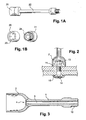
- An exemplary embodiment of the prior art is given in Figures 1A and 1B for a cup of the order of fifteen millimeters in diameter having holes of the order of 1 mm in diameter.
- This cup is screwed onto a feed tube of the product and makes it possible to cap the fastener to be coated and then to inject the coating product on the fastener.
- an operator caps the fastener element with the aid of the nozzle and triggers the injection of the insulating material into the cup around the element. of fixation.
- the cleaning of the nozzles requires expensive and polluting powerful solvents and the use of brushes or other tools especially to unclog the holes of the nozzles.
- the nozzles are generally made of aluminum, are screwed on end caps themselves of aluminum and have dimensions adapted to the fasteners to be coated, a particular nozzle corresponding to each fixing diameter.
- the present invention aims to provide coating nozzles easier to use than the nozzles of the prior art, easy to clean without using solvents and modular.
- the present invention mainly relates to a pasty material supply device according to claim 1
- the pasty material supply device of the prior art comprises a tip 22 on which a two-part nozzle 20, 21 is screwed, the first part 20 comprising a cup and holes 23 for dispensing the pasty product, these holes being in contact with each other. communication with a distribution chamber 24 made in a second part of the nozzle and fixed to the end piece 22.
- the device according to the invention described in figure 3 comprises a tip 1 for feeding the material and a coating nozzle 2.
- the document EP 0 181 483 describes for its part a nozzle provided with a hemispherical housing in front of a central opening of the nozzle, an applicator coming to rest in the hemispherical housing to distribute the pasty material in the central opening.
- the device according to the invention comprises a nozzle 2 provided with a central opening 4 bringing the pasty material on the object to be coated and the endpiece comprises a channel 3 for feeding the pasty material terminating at a first end of the endpiece into the central opening 4 of the nozzle 2.
- the tip has a second end 10 for attachment to an extruder gun 12 by screwing or any other means.
- the nozzle is bell-shaped around the central opening 4.
- the inner surface 5 of the nozzle is a continuous and smooth surface thus allowing a better distribution of the coating product than the nozzle of the prior art which comprises a flat bottom and a cylindrical annular ring.
- the coating product does not adhere to the continuous and smooth surface of the nozzle according to the invention.
- the material used to make the nozzle and the tip is preferably a polyethylene on which the pasty coating material and in particular a polyurethane sealant does not adhere.
- the device according to the invention comprises, for its cleaning, according to a first variant a cleaning tool comprising a demolding plug 6 inserted into the nozzle 2 and whose outer surface 7 is adapted to adhere to the pasty material 11 once polymerized.
- the insertion of the cap causes a portion of the product still to flow back into the device through the second end of the nozzle.
- the outer surface 7 of the demolding plug 6 according to the example is threaded to adhere to the pasty material 11.
- the demolding plug 6 is inserted into the nozzle 2 before polymerization of the pasty material, the material is allowed to polymerize and the material is introduced by removing the plug 6 from the nozzle.
- Another cleaning method according to the invention consists, once the polymerized putty, to connect the end 10 of the nozzle to a compressed air supply, for example a shut-off valve for compressed air.
- the air inlet has an end provided with sealed fastening means for the end 10 of the nozzle, in particular a tapping complementary to the threaded end of the end 10 to cooperate with this end and realize a tight connection.
- the valve is opened so that compressed air is blown into the nozzle so that this air exerts pressure on the polymerized putty and peels it off the walls of the mold.
- nozzle and the nozzle and the polymerized putty is removed by hand from the nozzle and the nozzle, the putty once removed can easily be removed from the nozzle by hand.
- the tip 1 is capable of receiving nozzles 2 of different sizes to allow the coating of fasteners 13, 14 of different sizes.
- the nozzle 1 and the nozzles 2 are provided with complementary snap-fastening means 8, 9.
- the snap fastening means 8, 9 comprise an annular flange 9 surrounding the first end of the nozzle 1 and a circular groove 8 around the central opening 4 of the nozzle 2 and simply pull on the nozzle to separate it the tip then force insert the nozzle into another nozzle to be able to coat other fasteners.
- the cap may comprise a link to attach to the nozzle or include streaks instead of an external thread.
- the device according to the invention is simple to perform inexpensively and unlikely to clog unlike the device of the prior art.
Landscapes
- Engineering & Computer Science (AREA)
- Mechanical Engineering (AREA)
- General Engineering & Computer Science (AREA)
- Coating Apparatus (AREA)
- Nozzles (AREA)
- Dental Tools And Instruments Or Auxiliary Dental Instruments (AREA)
- Paper (AREA)
- Confectionery (AREA)
- Manufacturing And Processing Devices For Dough (AREA)
- Inorganic Insulating Materials (AREA)
- Formation And Processing Of Food Products (AREA)
- Application Of Or Painting With Fluid Materials (AREA)
Description
- La présente invention concerne un dispositif de fourniture de matériau pâteux tel que matériau d'enrobage et notamment mastic notamment pour l'enrobage de dispositifs de fixation.
- Les matériaux d'enrobage tels que les mastics silicones ou polyuréthanes sont des matériaux collants, et qui, après polymérisation, deviennent extrêmement difficiles à décoller pour le nettoyage des outils.
- En outre, dans le cadre d'une utilisation de ces matériaux pour enrober des éléments de fixation tels que des têtes de boulons, des outils d'enrobage précis doivent être réalisés pour éviter les coulures de produit et des défauts d'aspect ou d'étanchéité.
- Les outils d'enrobage connus comportent des dispositifs à buses, se montant sur des pistolets extrudeur, pourvues d'un chambrage constitué par une coupelle cylindrique munie de trous de diffusion du produit. Un exemple de réalisation de l'art antérieur est donné en
figures 1A et 1B pour une coupelle de l'ordre d'une quinzaine de millimètres de diamètre comportant des trous de l'ordre de 1 mm de diamètre. - Cette coupelle est vissée sur un tube d'amenée du produit et permet de coiffer la fixation à enrober puis d'injecter le produit d'enrobage sur la fixation.
- Pour réaliser l'isolation et l'enrobage de l'élément de fixation, un opérateur vient coiffer l'élément de fixation à l'aide de la buse et déclenche l'injection du matériau d'isolation dans la coupelle autour de l'élément de fixation.
- Le nettoyage des buses nécessite des solvants puissants onéreux et polluants et l'utilisation de pinceaux ou autres outils notamment pour déboucher les trous des buses.
- Les buses sont généralement réalisées en aluminium, sont vissées sur des embouts eux-mêmes en aluminium et ont des dimensions adaptées aux fixations à enrober, une buse particulière correspondant à chaque diamètre de fixation.
- insert page 2a La présente invention a pour but de proposer des buses d'enrobage plus aisées d'emploi que les buses de l'art antérieur, faciles à nettoyer sans utiliser de solvants et modulaires.
- Pour ce faire, la présente invention concerne principalement un dispositif de fourniture de matériau pâteux selon la revendication 1
- L'utilisation d'une ouverture centrale permet un nettoyage aisé du dispositif et la forme en cloche de la buse permet une répartition plus homogène du produit d'enrobage.
- D'autres aspects et avantages de l'invention seront mieux compris à la lecture de la description qui va suivre d'un exemple de réalisation de l'invention non limitatif en référence aux figures qui représentent:
- en
figures 1A et 1B :des vues de côté et en perspective d'un embout et d'une buse de l'art antérieur; - en
figure 2 : une vue en coupe d'une buse selon l'invention autour d'un dispositif de fixation en cours d'enrobage; - en
figure 3 :une vue en coupe d'un dispositif selon l'invention; - en
figures 4A et 4B :le dispositif de lafigure 3 avant et pendant son nettoyage; - en
figure 5 : un détail du dispositif de lafigure 3 représentant la fixation de la buse sur l'embout. - Le dispositif de fourniture de matériau pâteux de l'art antérieur comprend un embout 22 sur lequel se visse une buse en deux parties 20, 21, la première partie 20 comprenant une coupelle et des trous 23 de distribution du produit pâteux, ces trous étant en communication avec une chambre de distribution 24 réalisée dans une seconde partie de la buse et fixée à l'embout 22.
- Comme pour l'art antérieur, le dispositif selon l'invention décrit en
figure 3 comporte un embout 1 d'amenée du matériau et une buse d'enrobage 2. - Notamment le document
US 5 322 361 décrit une buse connue prolongée par un tube de fixation sur un conteneur. - Le document
EP 0 181 483 décrit pour sa part une buse munie d'un logement hémisphérique en face d'une ouverture centrale de la buse, un applicateur venant s'appuyer dans le logement hémisphérique pour distribuer le matériau pâteux dans l'ouverture centrale. - Contrairement au système complexe de trous répartis sous une coupelle et de chambre de distribution de l'art antérieur, système risquant de se boucher facilement, le dispositif selon l'invention comporte une buse 2 pourvue d'une ouverture centrale 4 amenant le matériau pâteux sur l'objet à enrober et l'embout comporte un canal 3 d'amenée du matériau pâteux se terminant à une première extrémité de l'embout dans l'ouverture centrale 4 de la buse 2.
- L'embout comporte une seconde extrémité 10 de fixation sur un pistolet extrudeur 12 par vissage ou tout autre moyen.
- Pour enrober des objets tels que des dispositifs de fixation vis 14 écrou 13 comme représenté en
figure 2 , la buse est conformée en cloche autour de l'ouverture centrale 4. - En outre, la surface interne 5 de la buse est une surface continue et lisse permettant ainsi une meilleure répartition du produit d'enrobage que la buse de l'art antérieur qui comporte un fond plan et une couronne annulaire cylindrique.
- En outre, le produit d'enrobage n'adhère pas à la surface continue et lisse de la buse selon l'invention.
- Dans cette même optique, le matériau utilisé pour réaliser la buse et l'embout est avantageusement un polyéthylène sur lequel le matériau pâteux d'enrobage et notamment un mastic polyuréthane n'adhère pas.
- Comme représenté en
figures 4A et 4B , le dispositif selon l'invention comporte, pour son nettoyage, selon une première variante un outil de nettoyage comportant un bouchon de démoulage 6 s'insérant dans la buse 2 et dont la surface externe 7 est adaptée pour adhérer au matériau pâteux 11 une fois polymérisé. - Selon la
figure 4A , une fois l'enrobage terminé, l'opérateur retire l'embout 1 du pistolet extrudeur 12 et insère le bouchon 6 dans la buse. - L'insertion du bouchon fait refluer une partie du produit encore dans le dispositif par la seconde extrémité de l'embout.
- Une fois le produit polymérisé il suffit, pour nettoyer la buse et l'embout, de retirer le bouchon qui emporte avec lui le produit logé dans la buse et, de tirer sur le résidu de matériau sortant de l'extrémité 10 de l'embout 1.
- Pour faciliter l'accrochage du matériau, la surface externe 7 du bouchon de démoulage 6 selon l'exemple est filetée pour adhérer au matériau pâteux 11.
- Selon ce principe, on insère le bouchon de démoulage 6 dans la buse 2 avant polymérisation du matériau pâteux, on laisse polymériser le matériau et on entrait le matériau en sortant le bouchon 6 de la buse.
- Une autre méthode de nettoyage selon l'invention consiste, une fois le mastic polymérisé, à raccorder l'extrémité 10 de l'embout à une arrivée d'air comprimé, par exemple un robinet d'arrêt d'air comprimé. Pour ce faire, l'arrivée d'air comporte une extrémité munie de moyens de fixation étanches pour l'extrémité 10 de l'embout, notamment un taraudage complémentaire de l'extrémité filetée de l'extrémité 10 pour coopérer avec cette extrémité et réaliser une liaison étanche.
- Une fois l'extrémité 10 vissée sur le robinet, on ouvre le robinet de façon à ce qu'on insuffle de l'air comprimé dans l'embout afin que cet air exerce une pression sur le mastic polymérisé et le décolle des parois de l'embout et de la buse et on sort à la main le mastic polymérisé de la buse et de l'embout, le mastic une fois décollé pouvant aisément être sorti de la buse à la main.
- Dans le cadre de l'invention, l'embout 1 est susceptible de recevoir des buses 2 de tailles différentes pour permettre l'enrobage de fixations 13, 14 de différentes tailles.
- Pour faciliter le remplacement des buses, l'embout 1 et les buses 2 sont pourvus de moyens de fixation complémentaires encliquetables 8, 9.
- Selon l'exemple de la
figure 5 , les moyens de fixation encliquetables 8, 9 comportent un rebord annulaire 9 entourant la première extrémité de l'embout 1 et une gorge circulaire 8 autour de l'ouverture centrale 4 de la buse 2 et il suffit de tirer sur la buse pour la désolidariser de l'embout puis d'insérer à force l'embout dans une autre buse pour pouvoir enrober d'autres fixations. - L'invention ne se limite pas au dispositif décrit comme exemple et notamment le bouchon peut comporter un lien pour se fixer à la buse ou comporter des stries au lieu d'un filetage externe.
- Le dispositif selon l'invention est simple à réaliser peu onéreux et peu susceptible de se boucher contrairement au dispositif de l'art antérieur.
Claims (7)
- Dispositif de fourniture de matériau pâteux comportant un embout (1) d'amenée du matériau et une buse d'enrobage (2), l'embout comportant un canal (3) d'amenée du matériau pâteux se terminant à une première extrémité de l'embout dans une ouverture centrale (4) de la buse (2), caractérisé en ce que l'embout (1) est adapté à recevoir des buses (2) de tailles différentes, l'embout (1) et les buses (2) étant pourvus de moyens de fixation complémentaires encliquetables.
- Dispositif selon la revendication 1 caractérisé en ce que la buse est conformée en cloche autour de l'ouverture centrale (4).
- Dispositif selon la revendication 1 ou 2 caractérisé en ce que la surface interne (5) de la buse est une surface continue.
- Dispositif selon l'une quelconque des revendications précédentes caractérisé en ce que les moyens de fixation encliquetables (8, 9) comportent un rebord annulaire (9) entourant la première extrémité de l'embout (1) et une gorge circulaire (8) autour de l'ouverture centrale (4) de la buse (2).
- Dispositif selon l'une quelconque des revendications précédentes caractérisé en ce que l'embout comporte une seconde extrémité (10) de fixation sur un pistolet extrudeur (12).
- Dispositif selon l'une quelconque des revendications précédentes caractérisé en ce qu'il comporte un outil de nettoyage comportant un bouchon de démoulage (6) s'insérant dans la buse (2) et dont la surface externe (7) est adaptée pour adhérer au matériau pâteux (11) une fois polymérisé.
- Dispositif selon la revendication 6 caractérisé en ce que la surface externe (7) du bouchon de démoulage (6) est filetée pour adhérer au matériau pâteux (11).
Applications Claiming Priority (2)
| Application Number | Priority Date | Filing Date | Title |
|---|---|---|---|
| FR0452508A FR2877239B1 (fr) | 2004-11-03 | 2004-11-03 | Dispositif de fourniture de materiau pateux |
| PCT/FR2005/050893 WO2006048570A2 (fr) | 2004-11-03 | 2005-10-25 | Dispositif de fourniture de materiau pateux pour l'enrobage de dispositifs de fixation dispositif de fourniture de matériau pâteux |
Publications (2)
| Publication Number | Publication Date |
|---|---|
| EP1807254A2 EP1807254A2 (fr) | 2007-07-18 |
| EP1807254B1 true EP1807254B1 (fr) | 2010-12-29 |
Family
ID=34951045
Family Applications (1)
| Application Number | Title | Priority Date | Filing Date |
|---|---|---|---|
| EP05815716A Ceased EP1807254B1 (fr) | 2004-11-03 | 2005-10-25 | Dispositif de fourniture de materiau pateux |
Country Status (11)
| Country | Link |
|---|---|
| US (1) | US20090217868A1 (fr) |
| EP (1) | EP1807254B1 (fr) |
| JP (1) | JP4688880B2 (fr) |
| CN (1) | CN101048268A (fr) |
| AT (1) | ATE493255T1 (fr) |
| BR (1) | BRPI0517927A (fr) |
| CA (1) | CA2582502C (fr) |
| DE (1) | DE602005025668D1 (fr) |
| FR (1) | FR2877239B1 (fr) |
| RU (1) | RU2353516C2 (fr) |
| WO (1) | WO2006048570A2 (fr) |
Families Citing this family (19)
| Publication number | Priority date | Publication date | Assignee | Title |
|---|---|---|---|---|
| GB0624562D0 (en) * | 2006-12-08 | 2007-01-17 | Airbus Uk Ltd | Self Curing Injection Nozzle |
| CN101665414B (zh) | 2008-09-04 | 2012-12-12 | 中国科学院兰州化学物理研究所 | 离子液体催化合成聚甲氧基甲缩醛的方法 |
| GB2491799A (en) * | 2011-03-03 | 2012-12-19 | S & T Systems Ltd | Locking of threaded fasteners |
| PL2586537T3 (pl) * | 2011-10-31 | 2016-01-29 | Jurado Blazquez Miguel | Dysza do nakładania szczeliw za pomocą końcówki dzwonowej lub kapturkowej i przycisku do wtryskiwania |
| CN104321544B (zh) | 2012-04-11 | 2016-02-17 | Prc-迪索托国际公司 | 螺母板密封帽 |
| US9849637B2 (en) * | 2013-10-22 | 2017-12-26 | The Boeing Company | Self-centering sealant applicator |
| US10035287B2 (en) * | 2014-11-17 | 2018-07-31 | The Boeing Company | Method for sealing a fastener |
| EP3037191B8 (fr) * | 2014-12-22 | 2017-09-27 | KUKA Systems Aerospace | Dispositif d'application de fluides |
| DE102015100002A1 (de) * | 2015-01-02 | 2016-07-07 | Airbus Operations Gmbh | Verbindungsstellenversiegelung |
| EP3256542B1 (fr) | 2015-02-13 | 2022-07-06 | Chemetall GmbH | Matière d'étanchéité à base de composé époxy/polymère de base à terminaison mercapto et procédé de durcissement au moyen d'un catalyseur photolatent |
| US9968962B2 (en) * | 2015-03-19 | 2018-05-15 | The Boeing Company | Material applicator comprising a surface interface guide forming a continuous ring shaped flow channel with an unobstructive guding assembly therein |
| US11167310B2 (en) * | 2015-05-13 | 2021-11-09 | The Boeing Company | Sealing assembly for forming sealant coating on a fastener, the sealing assembly comprising a light generator and a forming cup associated with the light generator |
| FR3038861B1 (fr) * | 2015-07-16 | 2018-02-16 | Airbus Operations | Ensemble et procede de moulage d’un mastic de protection autour d’un element saillant. |
| DE102016123416A1 (de) * | 2016-12-05 | 2018-06-07 | Ba Assembly & Turnkey Systems Gmbh | Applikationseinheit |
| CN106738590B (zh) * | 2016-12-16 | 2023-01-17 | 浙江海峰自动化设备有限公司 | 一种用于pu材料的浇注头外套 |
| US10458455B2 (en) * | 2017-12-22 | 2019-10-29 | The Boeing Company | Systems and methods for making and using a fitted cap for applying a shaped sealant shroud to a portion of a fastener |
| US11819870B2 (en) | 2019-03-01 | 2023-11-21 | William Harrison | System and method for efficient and ergonomic waterproofing of joints and fasteners |
| FR3101261B3 (fr) * | 2019-09-30 | 2021-10-08 | Daher Aerospace | Dispositif et procédé pour l’application automatique d’un produit visqueux |
| CN114308573A (zh) * | 2021-12-03 | 2022-04-12 | 昌河飞机工业(集团)有限责任公司 | 一种用于螺母外表面密封胶涂覆的工装及涂覆方法 |
Family Cites Families (23)
| Publication number | Priority date | Publication date | Assignee | Title |
|---|---|---|---|---|
| DE976151C (de) * | 1952-10-04 | 1963-04-04 | Jos Zimmermann Nadelfabrik | Verfahren zum Umspritzen des verbreiterten Endes von nadel- oder nagelfoermigen Gegenstaenden mit einem Kunststoffkopf in einer Form |
| BE550793A (fr) * | 1956-09-01 | |||
| US2970773A (en) * | 1959-10-19 | 1961-02-07 | Minnesota Mining & Mfg | Fluid mixing and applying apparatus and method |
| US3238287A (en) * | 1962-04-27 | 1966-03-01 | Illinois Tool Works | Method for encapsulating a headed member with a molten material |
| US3581365A (en) * | 1965-12-08 | 1971-06-01 | Rubber Electronic Ind | Method of making valve element with molded resilient tip |
| US3440313A (en) * | 1967-02-27 | 1969-04-22 | Rubber Electronic Ind | Process of making rubber-tipped valve element |
| US3885492A (en) * | 1973-11-16 | 1975-05-27 | Elco Industries Inc | Capped fastener |
| JPS5344792Y2 (fr) * | 1974-05-20 | 1978-10-26 | ||
| US4115172A (en) * | 1977-04-04 | 1978-09-19 | Uniroyal, Inc. | Apparatus and method for applying puncture sealant material to a tire |
| US4312679A (en) * | 1978-03-27 | 1982-01-26 | Klein Sr Richard W | Method for cleaning clogged pipes |
| DE2815653A1 (de) * | 1978-04-11 | 1979-10-25 | Horst Schmiedeler | Verfahren und vorrichtung zum aufbringen eines, in einem behaelter angeordneten, pastenfoermigen dichtmittels |
| US4382049A (en) * | 1981-11-30 | 1983-05-03 | Mcdonnell Douglas Corporation | Forming a lightning spark isolation barrier |
| US4461454A (en) * | 1982-06-01 | 1984-07-24 | New Product, Inc. | Caulking tube valve |
| JPS6179610A (ja) * | 1984-09-28 | 1986-04-23 | Nippon Sueeji Kogyo Kk | 端子付きロ−プ等の製造方法 |
| DE3575333D1 (de) * | 1984-10-15 | 1990-02-15 | Ltv Aerospace & Defence | Verfahren und vorrichtung zum aufbringen einer bestimmten dichtungsmittelmenge auf ungeschuetzte befestigungsmittel. |
| US4917745A (en) * | 1988-09-22 | 1990-04-17 | Speer Lawrence L | Fabric repair process |
| BR9103896A (pt) * | 1991-09-10 | 1992-03-17 | Rojek Metalgrafica | Processo para a formacao de um furo de alivio com lacre obturador destacavel,para facil abertura,em tampas metalicas,de fechamento a vacuo,de copos e outros recipientes de vidro,que se prestam de embalagem para produtos alimenticios |
| US5322381A (en) * | 1992-05-15 | 1994-06-21 | Argo Ii Richard S | Sealant applicator and method for sealing headed fasteners |
| JP2578568B2 (ja) * | 1993-07-09 | 1997-02-05 | 日本ペイント株式会社 | 金属凸部の保護方法 |
| RU2091182C1 (ru) * | 1993-10-13 | 1997-09-27 | Чесноков Николай Михайлович | Способ нанесения покрытия (варианты), устройство для его осуществления и состав |
| US5458836B1 (en) * | 1994-03-11 | 1998-08-04 | Du Pont | Polymer extrusion die and use thereof |
| US6526908B2 (en) * | 2000-08-07 | 2003-03-04 | J. E. Grote Company, Inc. | Fluent material applicator |
| EP1216758A1 (fr) * | 2000-11-17 | 2002-06-26 | McLaws, Brent D. | Dispositif d'application de marques d'identification |
-
2004
- 2004-11-03 FR FR0452508A patent/FR2877239B1/fr not_active Expired - Fee Related
-
2005
- 2005-10-25 CA CA2582502A patent/CA2582502C/fr not_active Expired - Fee Related
- 2005-10-25 AT AT05815716T patent/ATE493255T1/de not_active IP Right Cessation
- 2005-10-25 WO PCT/FR2005/050893 patent/WO2006048570A2/fr not_active Ceased
- 2005-10-25 BR BRPI0517927-0A patent/BRPI0517927A/pt not_active IP Right Cessation
- 2005-10-25 CN CNA200580037303XA patent/CN101048268A/zh active Pending
- 2005-10-25 JP JP2007539620A patent/JP4688880B2/ja not_active Expired - Fee Related
- 2005-10-25 US US11/718,544 patent/US20090217868A1/en not_active Abandoned
- 2005-10-25 DE DE602005025668T patent/DE602005025668D1/de not_active Expired - Lifetime
- 2005-10-25 RU RU2007120584/12A patent/RU2353516C2/ru not_active IP Right Cessation
- 2005-10-25 EP EP05815716A patent/EP1807254B1/fr not_active Ceased
Also Published As
| Publication number | Publication date |
|---|---|
| CA2582502A1 (fr) | 2006-05-11 |
| ATE493255T1 (de) | 2011-01-15 |
| US20090217868A1 (en) | 2009-09-03 |
| RU2007120584A (ru) | 2008-12-10 |
| WO2006048570A3 (fr) | 2006-06-29 |
| JP4688880B2 (ja) | 2011-05-25 |
| DE602005025668D1 (de) | 2011-02-10 |
| CA2582502C (fr) | 2013-11-26 |
| JP2008518769A (ja) | 2008-06-05 |
| BRPI0517927A (pt) | 2008-10-21 |
| CN101048268A (zh) | 2007-10-03 |
| FR2877239B1 (fr) | 2007-02-23 |
| WO2006048570A2 (fr) | 2006-05-11 |
| FR2877239A1 (fr) | 2006-05-05 |
| EP1807254A2 (fr) | 2007-07-18 |
| RU2353516C2 (ru) | 2009-04-27 |
Similar Documents
| Publication | Publication Date | Title |
|---|---|---|
| CA2582502C (fr) | Dispositif de fourniture de materiau pateux | |
| EP1503860B1 (fr) | Tete de pulverisation d'un produit tel que de la peinture | |
| EP1020231B1 (fr) | Tête de pulvérisation d'un produit tel que de la peinture | |
| EP3139790B1 (fr) | Ensemble de distribution et d'application de produit fluide | |
| FR2900583A1 (fr) | Pulverisateur de texture | |
| EP0670275A1 (fr) | Dispositif de distribution à fermeture étanche pour un récipient pressurisé ou d'un récipient à pompe | |
| FR2671329A1 (fr) | Embout-poussoir a jets multiples et a fermeture. | |
| FR2774928A1 (fr) | Element et dispositif d'alimentation pour pistolet de projection d'un liquide, et pistolet correspondant | |
| EP0433143A1 (fr) | Dispositif support de buses, à changement rapide | |
| FR2787731A1 (fr) | Tete de distribution demontable | |
| JP2010207808A (ja) | 液体吐出組立体 | |
| FR2798868A1 (fr) | Ensemble d'alimentation pour pistolet de projection d'un liquide et pistolet pourvu d'un tel ensemble | |
| FR3018703B1 (fr) | Dispositif de maintien d'une tetine de pipetage et distributeur compte-gouttes | |
| EP2454067A1 (fr) | Dispositif interface perfectionne d'injection | |
| WO2002057672A1 (fr) | Vanne a pointeau a commande pneumatique | |
| FR2732245A1 (fr) | Organe de distribution pour la pulverisation simultanee de deux produits et dispositif de conditionnement equipe d'un tel organe de distribution | |
| EP2111364A2 (fr) | Tete de distribution de produit fluide | |
| CA2349695A1 (fr) | Tete de distribution nettoyable, et distributeur ainsi equipe | |
| FR2884157A1 (fr) | Tete de distribution | |
| US8470096B2 (en) | Paint bell cup cleaning method | |
| EP1227993A1 (fr) | Distributeur de melange de produit extemporane | |
| EP1726538B1 (fr) | Dispositif diffuseur à jets multiples pour bombes aérosols | |
| EP1914177A1 (fr) | Dispositif de distribution pour produit fluide | |
| FR2674773A1 (fr) | Pistolet automatique pour projeter un produit de revetement sur des objets. | |
| FR2540405A3 (fr) | Rampe de pulverisation pour l'agriculture |
Legal Events
| Date | Code | Title | Description |
|---|---|---|---|
| PUAI | Public reference made under article 153(3) epc to a published international application that has entered the european phase |
Free format text: ORIGINAL CODE: 0009012 |
|
| 17P | Request for examination filed |
Effective date: 20070427 |
|
| AK | Designated contracting states |
Kind code of ref document: A2 Designated state(s): AT BE BG CH CY CZ DE DK EE ES FI FR GB GR HU IE IS IT LI LT LU LV MC NL PL PT RO SE SI SK TR |
|
| 17Q | First examination report despatched |
Effective date: 20071001 |
|
| DAX | Request for extension of the european patent (deleted) | ||
| RAP1 | Party data changed (applicant data changed or rights of an application transferred) |
Owner name: AIRBUS OPERATIONS (S.A.S) |
|
| GRAP | Despatch of communication of intention to grant a patent |
Free format text: ORIGINAL CODE: EPIDOSNIGR1 |
|
| GRAS | Grant fee paid |
Free format text: ORIGINAL CODE: EPIDOSNIGR3 |
|
| GRAA | (expected) grant |
Free format text: ORIGINAL CODE: 0009210 |
|
| AK | Designated contracting states |
Kind code of ref document: B1 Designated state(s): AT BE BG CH CY CZ DE DK EE ES FI FR GB GR HU IE IS IT LI LT LU LV MC NL PL PT RO SE SI SK TR |
|
| REG | Reference to a national code |
Ref country code: GB Ref legal event code: FG4D Free format text: NOT ENGLISH |
|
| REG | Reference to a national code |
Ref country code: CH Ref legal event code: EP |
|
| REG | Reference to a national code |
Ref country code: IE Ref legal event code: FG4D Free format text: LANGUAGE OF EP DOCUMENT: FRENCH |
|
| REF | Corresponds to: |
Ref document number: 602005025668 Country of ref document: DE Date of ref document: 20110210 Kind code of ref document: P |
|
| REG | Reference to a national code |
Ref country code: DE Ref legal event code: R096 Ref document number: 602005025668 Country of ref document: DE Effective date: 20110210 |
|
| REG | Reference to a national code |
Ref country code: NL Ref legal event code: VDEP Effective date: 20101229 |
|
| PG25 | Lapsed in a contracting state [announced via postgrant information from national office to epo] |
Ref country code: LT Free format text: LAPSE BECAUSE OF FAILURE TO SUBMIT A TRANSLATION OF THE DESCRIPTION OR TO PAY THE FEE WITHIN THE PRESCRIBED TIME-LIMIT Effective date: 20101229 |
|
| LTIE | Lt: invalidation of european patent or patent extension |
Effective date: 20101229 |
|
| PG25 | Lapsed in a contracting state [announced via postgrant information from national office to epo] |
Ref country code: AT Free format text: LAPSE BECAUSE OF FAILURE TO SUBMIT A TRANSLATION OF THE DESCRIPTION OR TO PAY THE FEE WITHIN THE PRESCRIBED TIME-LIMIT Effective date: 20101229 Ref country code: FI Free format text: LAPSE BECAUSE OF FAILURE TO SUBMIT A TRANSLATION OF THE DESCRIPTION OR TO PAY THE FEE WITHIN THE PRESCRIBED TIME-LIMIT Effective date: 20101229 Ref country code: CY Free format text: LAPSE BECAUSE OF FAILURE TO SUBMIT A TRANSLATION OF THE DESCRIPTION OR TO PAY THE FEE WITHIN THE PRESCRIBED TIME-LIMIT Effective date: 20101229 Ref country code: LV Free format text: LAPSE BECAUSE OF FAILURE TO SUBMIT A TRANSLATION OF THE DESCRIPTION OR TO PAY THE FEE WITHIN THE PRESCRIBED TIME-LIMIT Effective date: 20101229 Ref country code: SE Free format text: LAPSE BECAUSE OF FAILURE TO SUBMIT A TRANSLATION OF THE DESCRIPTION OR TO PAY THE FEE WITHIN THE PRESCRIBED TIME-LIMIT Effective date: 20101229 Ref country code: BG Free format text: LAPSE BECAUSE OF FAILURE TO SUBMIT A TRANSLATION OF THE DESCRIPTION OR TO PAY THE FEE WITHIN THE PRESCRIBED TIME-LIMIT Effective date: 20110329 Ref country code: SI Free format text: LAPSE BECAUSE OF FAILURE TO SUBMIT A TRANSLATION OF THE DESCRIPTION OR TO PAY THE FEE WITHIN THE PRESCRIBED TIME-LIMIT Effective date: 20101229 |
|
| REG | Reference to a national code |
Ref country code: IE Ref legal event code: FD4D |
|
| PG25 | Lapsed in a contracting state [announced via postgrant information from national office to epo] |
Ref country code: ES Free format text: LAPSE BECAUSE OF FAILURE TO SUBMIT A TRANSLATION OF THE DESCRIPTION OR TO PAY THE FEE WITHIN THE PRESCRIBED TIME-LIMIT Effective date: 20110409 Ref country code: IS Free format text: LAPSE BECAUSE OF FAILURE TO SUBMIT A TRANSLATION OF THE DESCRIPTION OR TO PAY THE FEE WITHIN THE PRESCRIBED TIME-LIMIT Effective date: 20110429 Ref country code: GR Free format text: LAPSE BECAUSE OF FAILURE TO SUBMIT A TRANSLATION OF THE DESCRIPTION OR TO PAY THE FEE WITHIN THE PRESCRIBED TIME-LIMIT Effective date: 20110330 Ref country code: EE Free format text: LAPSE BECAUSE OF FAILURE TO SUBMIT A TRANSLATION OF THE DESCRIPTION OR TO PAY THE FEE WITHIN THE PRESCRIBED TIME-LIMIT Effective date: 20101229 Ref country code: CZ Free format text: LAPSE BECAUSE OF FAILURE TO SUBMIT A TRANSLATION OF THE DESCRIPTION OR TO PAY THE FEE WITHIN THE PRESCRIBED TIME-LIMIT Effective date: 20101229 Ref country code: PT Free format text: LAPSE BECAUSE OF FAILURE TO SUBMIT A TRANSLATION OF THE DESCRIPTION OR TO PAY THE FEE WITHIN THE PRESCRIBED TIME-LIMIT Effective date: 20110429 |
|
| PG25 | Lapsed in a contracting state [announced via postgrant information from national office to epo] |
Ref country code: SK Free format text: LAPSE BECAUSE OF FAILURE TO SUBMIT A TRANSLATION OF THE DESCRIPTION OR TO PAY THE FEE WITHIN THE PRESCRIBED TIME-LIMIT Effective date: 20101229 Ref country code: NL Free format text: LAPSE BECAUSE OF FAILURE TO SUBMIT A TRANSLATION OF THE DESCRIPTION OR TO PAY THE FEE WITHIN THE PRESCRIBED TIME-LIMIT Effective date: 20101229 Ref country code: RO Free format text: LAPSE BECAUSE OF FAILURE TO SUBMIT A TRANSLATION OF THE DESCRIPTION OR TO PAY THE FEE WITHIN THE PRESCRIBED TIME-LIMIT Effective date: 20101229 Ref country code: PL Free format text: LAPSE BECAUSE OF FAILURE TO SUBMIT A TRANSLATION OF THE DESCRIPTION OR TO PAY THE FEE WITHIN THE PRESCRIBED TIME-LIMIT Effective date: 20101229 |
|
| PG25 | Lapsed in a contracting state [announced via postgrant information from national office to epo] |
Ref country code: DK Free format text: LAPSE BECAUSE OF FAILURE TO SUBMIT A TRANSLATION OF THE DESCRIPTION OR TO PAY THE FEE WITHIN THE PRESCRIBED TIME-LIMIT Effective date: 20101229 Ref country code: IE Free format text: LAPSE BECAUSE OF FAILURE TO SUBMIT A TRANSLATION OF THE DESCRIPTION OR TO PAY THE FEE WITHIN THE PRESCRIBED TIME-LIMIT Effective date: 20101229 |
|
| PLBE | No opposition filed within time limit |
Free format text: ORIGINAL CODE: 0009261 |
|
| STAA | Information on the status of an ep patent application or granted ep patent |
Free format text: STATUS: NO OPPOSITION FILED WITHIN TIME LIMIT |
|
| 26N | No opposition filed |
Effective date: 20110930 |
|
| REG | Reference to a national code |
Ref country code: DE Ref legal event code: R097 Ref document number: 602005025668 Country of ref document: DE Effective date: 20110930 |
|
| BERE | Be: lapsed |
Owner name: AIRBUS OPERATIONS (S.A.S) Effective date: 20111031 |
|
| PG25 | Lapsed in a contracting state [announced via postgrant information from national office to epo] |
Ref country code: MC Free format text: LAPSE BECAUSE OF NON-PAYMENT OF DUE FEES Effective date: 20111031 |
|
| REG | Reference to a national code |
Ref country code: CH Ref legal event code: PL |
|
| PG25 | Lapsed in a contracting state [announced via postgrant information from national office to epo] |
Ref country code: BE Free format text: LAPSE BECAUSE OF NON-PAYMENT OF DUE FEES Effective date: 20111031 Ref country code: LI Free format text: LAPSE BECAUSE OF NON-PAYMENT OF DUE FEES Effective date: 20111031 Ref country code: CH Free format text: LAPSE BECAUSE OF NON-PAYMENT OF DUE FEES Effective date: 20111031 |
|
| PGFP | Annual fee paid to national office [announced via postgrant information from national office to epo] |
Ref country code: IT Payment date: 20121024 Year of fee payment: 8 |
|
| PG25 | Lapsed in a contracting state [announced via postgrant information from national office to epo] |
Ref country code: LU Free format text: LAPSE BECAUSE OF NON-PAYMENT OF DUE FEES Effective date: 20111025 |
|
| PG25 | Lapsed in a contracting state [announced via postgrant information from national office to epo] |
Ref country code: TR Free format text: LAPSE BECAUSE OF FAILURE TO SUBMIT A TRANSLATION OF THE DESCRIPTION OR TO PAY THE FEE WITHIN THE PRESCRIBED TIME-LIMIT Effective date: 20101229 |
|
| PG25 | Lapsed in a contracting state [announced via postgrant information from national office to epo] |
Ref country code: HU Free format text: LAPSE BECAUSE OF FAILURE TO SUBMIT A TRANSLATION OF THE DESCRIPTION OR TO PAY THE FEE WITHIN THE PRESCRIBED TIME-LIMIT Effective date: 20101229 |
|
| PG25 | Lapsed in a contracting state [announced via postgrant information from national office to epo] |
Ref country code: IT Free format text: LAPSE BECAUSE OF NON-PAYMENT OF DUE FEES Effective date: 20131025 |
|
| REG | Reference to a national code |
Ref country code: FR Ref legal event code: PLFP Year of fee payment: 11 |
|
| PGFP | Annual fee paid to national office [announced via postgrant information from national office to epo] |
Ref country code: DE Payment date: 20151022 Year of fee payment: 11 |
|
| REG | Reference to a national code |
Ref country code: FR Ref legal event code: PLFP Year of fee payment: 12 |
|
| REG | Reference to a national code |
Ref country code: DE Ref legal event code: R119 Ref document number: 602005025668 Country of ref document: DE |
|
| PG25 | Lapsed in a contracting state [announced via postgrant information from national office to epo] |
Ref country code: DE Free format text: LAPSE BECAUSE OF NON-PAYMENT OF DUE FEES Effective date: 20170503 |
|
| REG | Reference to a national code |
Ref country code: FR Ref legal event code: PLFP Year of fee payment: 13 |
|
| PGFP | Annual fee paid to national office [announced via postgrant information from national office to epo] |
Ref country code: FR Payment date: 20171024 Year of fee payment: 13 |
|
| PGFP | Annual fee paid to national office [announced via postgrant information from national office to epo] |
Ref country code: GB Payment date: 20171019 Year of fee payment: 13 |
|
| GBPC | Gb: european patent ceased through non-payment of renewal fee |
Effective date: 20181025 |
|
| PG25 | Lapsed in a contracting state [announced via postgrant information from national office to epo] |
Ref country code: FR Free format text: LAPSE BECAUSE OF NON-PAYMENT OF DUE FEES Effective date: 20181031 |
|
| PG25 | Lapsed in a contracting state [announced via postgrant information from national office to epo] |
Ref country code: GB Free format text: LAPSE BECAUSE OF NON-PAYMENT OF DUE FEES Effective date: 20181025 |