EP1808065A1 - Ballenumhüllungvorrichtung und -verfahren für landwirtschaftliche Arbeitsmaschinen - Google Patents
Ballenumhüllungvorrichtung und -verfahren für landwirtschaftliche Arbeitsmaschinen Download PDFInfo
- Publication number
- EP1808065A1 EP1808065A1 EP06425014A EP06425014A EP1808065A1 EP 1808065 A1 EP1808065 A1 EP 1808065A1 EP 06425014 A EP06425014 A EP 06425014A EP 06425014 A EP06425014 A EP 06425014A EP 1808065 A1 EP1808065 A1 EP 1808065A1
- Authority
- EP
- European Patent Office
- Prior art keywords
- inlet
- sheet material
- bale
- supporting means
- wrapping
- Prior art date
- Legal status (The legal status is an assumption and is not a legal conclusion. Google has not performed a legal analysis and makes no representation as to the accuracy of the status listed.)
- Granted
Links
- 238000000034 method Methods 0.000 title claims abstract description 13
- 239000000463 material Substances 0.000 claims abstract description 56
- 230000033001 locomotion Effects 0.000 claims description 19
- 238000004804 winding Methods 0.000 claims description 6
- 230000006835 compression Effects 0.000 claims description 4
- 238000007906 compression Methods 0.000 claims description 4
- 238000005520 cutting process Methods 0.000 claims description 4
- 230000005484 gravity Effects 0.000 description 3
- 230000007246 mechanism Effects 0.000 description 3
- 239000004459 forage Substances 0.000 description 2
- 238000003780 insertion Methods 0.000 description 2
- 230000037431 insertion Effects 0.000 description 2
- 230000001681 protective effect Effects 0.000 description 2
- 230000000284 resting effect Effects 0.000 description 2
- 244000025254 Cannabis sativa Species 0.000 description 1
- 238000013459 approach Methods 0.000 description 1
- 238000000151 deposition Methods 0.000 description 1
- 230000000694 effects Effects 0.000 description 1
- 238000003306 harvesting Methods 0.000 description 1
- 239000004463 hay Substances 0.000 description 1
- 230000002452 interceptive effect Effects 0.000 description 1
- 238000004519 manufacturing process Methods 0.000 description 1
- 239000002184 metal Substances 0.000 description 1
- 239000007769 metal material Substances 0.000 description 1
- 230000036961 partial effect Effects 0.000 description 1
- 230000002829 reductive effect Effects 0.000 description 1
- 239000010902 straw Substances 0.000 description 1
- 238000009941 weaving Methods 0.000 description 1
Images




Classifications
-
- A—HUMAN NECESSITIES
- A01—AGRICULTURE; FORESTRY; ANIMAL HUSBANDRY; HUNTING; TRAPPING; FISHING
- A01F—PROCESSING OF HARVESTED PRODUCE; HAY OR STRAW PRESSES; DEVICES FOR STORING AGRICULTURAL OR HORTICULTURAL PRODUCE
- A01F15/00—Baling presses for straw, hay or the like
- A01F15/07—Rotobalers, i.e. machines for forming cylindrical bales by winding and pressing
- A01F15/071—Wrapping devices
- A01F15/0715—Wrapping the bale in the press chamber before opening said chamber
Definitions
- the present invention refers to a bale wrapping device for agricultural machines and to the related method.
- balers In the field of agricultural machines there is a category of machinery, generally referred to as round balers, allowing to pick crop material, like, e.g. forage, and to compact it in the form of a cylindrical bale.
- the crop material is inletted into a forming chamber where, by means of cylindrical rollers and belts, the material is set in rotation and compacted until obtaining cylindrical bales of desired dimensions or density.
- the former is usually wrapped, typically by means of a net or other material in the form of sheets.
- round balers are usually equipped with a wrapping device.
- Such devices feed net or other wrapping material, supplied by a reel that generally is arranged in a position side-by-side to the harvesting chamber, and means for transferring the wrapping material from the reel toward the bale forming chamber.
- Said transferring means have the task of bringing the net near to the bale forming chamber.
- the wrapping is completed and the net can be cut so as to allow the ejection of the bale thus prepared.
- the devices carrying out this function should not interfere in the bale forming step; otherwise, the net might cling to the bale during its forming and, in addition, the picked material that is frequently outletted from the forming chamber might hinder the normal operation of the wrapping device.
- a further critical aspect concerns the positioning of the wrapping device, which may be placed in different locations on the round baler, in particular depending on the type of machine utilized.
- the wrapping device is positioned so as to exploit the action of gravity and deliver the net inside the chamber by descent.
- the inserting of the net can take place in the front portion of the machine, more precisely between two elements contributing to the holding or the tumbling of the bale, like, e.g., a roller and a crossbar, or two rollers.
- the wrapping device in a manner such as to carry out the inletting of the net in the front portion, as in this case the operation is more reliable, beside being more easily controllable by the operator aboard the machine.
- difficult produce like, e.g., green grass.
- the bale forming chamber has variable volume, by means of a system generally consisting of rollers and belts that, around a starting core, diametrally increases the bale up to a size requested by the customer.
- EP 432 830 to New Holland, describes a retractable system gripping the net to bring it near to the inlet chamber, concomitantly uncoiling it from a reel. Then, the same holding member lets the net run over, as it is wound up by means of the rotation of the bale.
- a disadvantage shared by all of said wrapping devices is that the means for transferring the wrapping material consist of rollers or articulated mechanisms. Suchlike transferring means exhibit however limitations with regard to their effectiveness in transferring the wrapping material, as well as to their relative dimensions.
- the technical problem underlying the present invention is to provide a bale wrapping system overcoming the drawbacks mentioned above with reference to the known art.
- bale wrapping device for agricultural machines according to claim 1 and by the wrapping method according to claim 11.
- the present invention provides several relevant advantages.
- the main advantage lies in effectively carrying out the wrapping, still optionally locating the wrapping device anywhere on the machine, in particular frontally, even in case of round balers with variable volume chamber, said wrapping being in no way affected by any outletting of material nor requiring the use of additional bulkheads.
- the device according to the present invention is of simple and cost-effective implementation, also having reduced dimensions.
- a further advantage concerns the step of replacing the net reel, which may take place over short times and without requiring complex operations.
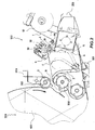
- an agricultural machine 200 for forming a bale 400 in particular a round baler, comprises a pickup 201 for lifting crop material 300, such as hay, straw, forage or other green or dry produce, from the ground to bring it into a forming chamber 202.
- crop material 300 such as hay, straw, forage or other green or dry produce
- the round baler 200 is connected, at a front portion thereof, to a tractor or other means, not illustrated in the figure, by means of a hook and a suitable drive train 203.
- the round baler further comprises a device 100 for wrapping the bale, preferably located in front of the forming chamber, basically at said front portion.
- the wrapping device 100 allows to insert a sheet material 1, in the present embodiment in the form of a net, into the forming chamber 202 for forming the bale 400, to wind it up around the latter and then perform the cutting of the material 1.
- the sheet material 1 is coiled on a reel 10 which may be gradually uncoiled to supply a desired length of material.
- the wrapping device comprises feeding means 2, implemented by a pair of rolls 21 and 22, between which the net 1 is positioned.
- the feeding means does not have to be located near to the forming chamber, thereby reducing the problems related to the outletting of crop material.
- the feeding means comprises a spreader roller 24, arranged in an intermediate position between the reel and the rolls.
- a first drive roll 21 is made of rubber and, connected to an electric clutch or an electric motor, provides traction to the net 1.
- the second compression roll 22 is pressed against the former roll by means of suitable compression means 23, and is instead made of metallic material.
- the drive roll 21 is connected to an electric clutch allowing to relieve the traction and make the roll idle during suitable wrapping steps.
- the feeding means 2 may let the net 1 advance freely when the latter is dragged otherwise.
- the net 1 is inserted into the forming chamber 202 through an inlet 5 that, according to the present embodiment, is obtained between a roller 205 onto which there run belts 204 for forming the bale 400, and a tumbling roller 206.
- the inlet 5 may be located in other positions, optionally facilitating the insertion of the net into the chamber.
- a certain quantity of crop material may be outletted from the inlet 5; as it can be seen in figure 2, the feeding means are located at a distance from the inlet 5 allowing to prevent said material from depositing in excess on said means.
- Said outletting of material is basically unavoidable, as, whatever the system used, a sufficiently wide space should be provided for the transit of the net and of the related means for inletting into the forming chamber.
- variable chamber machines like the one shown in figure 1, by locating the feeding means at such a distance from the inlet it is not possible to use the sole gravity to bring the net 1 from the feeding means to the inlet 5.
- the wrapping device is located in a position sufficiently low to allow even the wrapping of small-sized bales.
- the device according to the present invention comprises means 3 for supporting the net 1, allowing to support the latter while it advances toward the inlet 5 and toward the forming chamber.
- the supporting means 3 can supportingly receive the net 1 in a manner such that the latter, while being uncoiled from the reel 10, or anyhow supplied by the feeding means, approaches the inlet 5.
- the supporting means is movable from a receiving position 6, far from the inlet 5 of the chamber 202, to a position near thereto, as illustrated in figure 2.
- the feeding means 2 is such as to supply the net 1 at a region intermediate between said two positions.
- the feeding means can supply a portion 11 of net interfering with the motion of the supporting means.
- the supporting means 3 can urge and supportingly receive the net 1 and bring it near to the inlet 5.
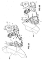
- the supporting means is implemented with bars 32, pivotally connected to the frame of the agricultural machine, between which a supporting plate 31 is arranged, as illustrated in figure 3.
- the supporting plate can have a serration at one end thereof, so as to allow the net to get caught in correspondence of a set of teeth, not illustrated in the figure.
- the bars 32 can pivot about an axis of rotation 33 so as to move the plate from the receiving position 6 to that near to the inlet 5.
- the pivoting of the bars is carried out by means of the releasing of an elastic element, in particular a spring, not illustrated in the figure, which is prewound by an electric motor.
- the electric motor allows to bring the bars 32 from the inlet to the receiving position 6. Moreover, such a motion concomitantly allows to wind up the spring.
- the supporting means can return, urged by the action of the elastic element, into the position near to the inlet.
- the plate carries out an action of tensioning and/or supporting the sheet material 1, during the approaching to the inlet 5.
- the plate carries out the sole supporting of the material, thereby allowing the sliding of the latter onto the plate, toward the forming chamber.
- the operation of the wrapping device according to the present invention is based on the combined action of the feeding means 2 and of the supporting means 3.
- the wrapping of the bale is carried out according to a method initially envisaging a step in which the supporting means is shifted from the position near to the inlet 5 to the receiving position 6.
- the motion of the supporting means is not hindered by the net 1, as the latter is held sufficiently near to the feeding means 2.
- the net Upon having brought the supporting means in the receiving position 6, the net is supplied by the feeding means 2.
- the latter uncoil a length of net such as to supply at least a portion that may interfere with the motion of the supporting means 3 from the receiving position 6 to that near to the inlet 5.
- the feeding means 2 is such as to supply the net 1 in a region intermediate between said positions.
- the supporting means is then shifted toward the position near to the inlet 5, so as to bring the portion of net near to the latter.
- This motion occurs by means of the action of tensioning and/or supporting onto the portion 11 of net that the supporting means, and in particular the plate 31, exert during their pivoting.
- the motion of the supporting means is not capable of tensioning the net, merely of keeping it there. There are teeth holding the net.
- the plate 31 urges the net 1 toward the inlet 5; then, upon reaching a position near thereto, said plate supports the net resting thereon as the latter enters the forming chamber 202 and is wound up around the bale 400.
- the net 1 is advanced by means of the rolls 21 and 22, that therefore at the approaching of the inlet gradually supply the net, until it reaches the forming chamber and the bale so as to be dragged by the motion of rotation of the latter.
- the feeding means cooperate with the supporting means, in a manner such that the latter appear at the inlet 5 with the net resting on the plate 31.
- the plate has a shape such as to stop the net during the rotation toward the inlet, in particular, as mentioned above, by means of the serration. Accordingly, after the arm 32, urged by the spring, has traveled a certain angular sector, the net is tensioned by the plate 31.
- the spring does not have a force sufficing to uncoil additional net and therefore drag the latter toward the inlet; therefore, the travel of the supporting means is interrupted.
- the drive roll 21 supplies additional net, until arriving, with subsequent pulses, near said position.
- a suitable control system allows to control the drive roll 21 when the net is tensioned owing to the action of the spring.
- the feeding means can supply the net in a manner continuous and coordinated with the angular shifting of the bars 32, so that during the advancing of the net toward the inlet the portion 11 of net always rests onto the plate 31.
- the feeding means 2 comprises a rotation sensor, allowing to indirectly calculate the length of the net uncoiled by the rolls.
- the drive roll 21 upon reaching the position near to the inlet the drive roll 21 continues to supply net, which thus can freely enter into the chamber 202, so as to be dragged in rotation by the bale, winding thereabout.
- the serration on the plate 31 is such that the net does not get caught anymore when the supporting means lies in a location near to the inlet. Therefore, in such a location the net may freely slide onto the plate, kept as support.
- step of inserting may take place by subsequent pulses.
- the drive roll 21 supplies the net at small discrete intervals.
- the wrapping goes on by winding up the bale for some revolutions, optionally utilizing a preset length of net, such as to obtain a stable and compact product, according to the type of crop material.
- the net 1 is cut with suitable cutting means 4 that, in the present embodiment, basically consists of horizontally pivoted knives.
- the knives act in particular at the outlet of the feeding means, so that a portion of net remains anyhow comprised between the rolls 21 and 22, to be fed at the subsequent wrapping.
- the bale 400 once wound up by the net 1, is then ejected from the chamber 202, and the agricultural machine is ready to form a new bale.
- the device according to the present invention entails a further significant advantage during the same forming of the bale.
- the supporting means 3, and in particular the plate 31, are conveniently kept near the inlet 5 during the forming of the bale.
- the outletting of crop material from the chamber 202 is inhibited, or anyhow markedly limited. As already described, this feature prevents said material from hindering the motions of the components of the device, and above all of the net 1.
- the round balers can also comprise a twine wrapper, not illustrated in the figure, that is usually located above or below the feeding means.
- the supporting means may also be utilized as protective bulkhead for such twine wrappers.
- Said bulkhead may be opened during the operation of these devices, them also needing access to the forming chamber.
- the device and the method according to the present invention allow to carry out this important function, without the use of additional bulkheads or other components.
- the reel 10 may remain always braked by means of a suitable brake, not illustrated in the figure, as the motion of the net, during the step of reinserting and reactivating, is carried out by the feeding means 2.
- This feature allows to avoid the use of special brake-disengaging mechanism, usually present in other known constructive solutions, to allow the uncoiling of the reel.
- the supporting means may be removed from the inlet 5 even some instants prior to the complete forming of the bale, as the former, by being in a position quite near to the chamber, could interfere with the bale in the final instants of forming.
- the inserting of the net is always braked, and therefore already in an optimal position.
Landscapes
- Life Sciences & Earth Sciences (AREA)
- Environmental Sciences (AREA)
- Storage Of Harvested Produce (AREA)
- Packaging Of Special Articles (AREA)
- Preliminary Treatment Of Fibers (AREA)
- Soil Working Implements (AREA)
- Sowing (AREA)
Priority Applications (3)
| Application Number | Priority Date | Filing Date | Title |
|---|---|---|---|
| AT06425014T ATE398917T1 (de) | 2006-01-13 | 2006-01-13 | Ballenumhüllungvorrichtung und -verfahren für landwirtschaftliche arbeitsmaschinen |
| DE602006001571T DE602006001571D1 (de) | 2006-01-13 | 2006-01-13 | Ballenumhüllungvorrichtung und -verfahren für landwirtschaftliche Arbeitsmaschinen |
| EP06425014A EP1808065B1 (de) | 2006-01-13 | 2006-01-13 | Ballenumhüllungvorrichtung und -verfahren für landwirtschaftliche Arbeitsmaschinen |
Applications Claiming Priority (1)
| Application Number | Priority Date | Filing Date | Title |
|---|---|---|---|
| EP06425014A EP1808065B1 (de) | 2006-01-13 | 2006-01-13 | Ballenumhüllungvorrichtung und -verfahren für landwirtschaftliche Arbeitsmaschinen |
Publications (2)
| Publication Number | Publication Date |
|---|---|
| EP1808065A1 true EP1808065A1 (de) | 2007-07-18 |
| EP1808065B1 EP1808065B1 (de) | 2008-06-25 |
Family
ID=36228773
Family Applications (1)
| Application Number | Title | Priority Date | Filing Date |
|---|---|---|---|
| EP06425014A Expired - Lifetime EP1808065B1 (de) | 2006-01-13 | 2006-01-13 | Ballenumhüllungvorrichtung und -verfahren für landwirtschaftliche Arbeitsmaschinen |
Country Status (3)
| Country | Link |
|---|---|
| EP (1) | EP1808065B1 (de) |
| AT (1) | ATE398917T1 (de) |
| DE (1) | DE602006001571D1 (de) |
Cited By (9)
| Publication number | Priority date | Publication date | Assignee | Title |
|---|---|---|---|---|
| WO2011033494A1 (en) * | 2009-09-17 | 2011-03-24 | Solveside Limited | A baler |
| NL2010352C2 (en) * | 2013-02-22 | 2014-08-25 | Forage Innovations Bv | Wrapping material feeding device and method with cleaning function. |
| NL2010350C2 (en) * | 2013-02-22 | 2014-08-25 | Forage Innovations Bv | Apparatus and method for pushing wrapping material into a chamber. |
| EP2769616A2 (de) | 2013-02-22 | 2014-08-27 | Forage Innovations B.V. | Vorrichtung und Verfahren zum Zuführen von Verpackungsmaterial in eine Kammer |
| EP2777380A1 (de) * | 2013-03-15 | 2014-09-17 | CNH Industrial Belgium nv | Netzwickelsystem mit Gegenwickelrolle |
| WO2016114652A1 (en) | 2015-01-16 | 2016-07-21 | Forage Innovations B.V. | Apparatus and method for forming and quickly wrapping a bale in a bale forming chamber |
| WO2017078517A1 (en) * | 2015-11-02 | 2017-05-11 | Forage Innovations B.V. | Bale forming and wrapping apparatus and method with a pivotal web pusher |
| EP3300586A1 (de) * | 2016-09-28 | 2018-04-04 | Usines Claas France S.A.S | Ballenpresse |
| WO2021219534A1 (en) * | 2020-04-27 | 2021-11-04 | Kuhn-Geldrop Bv | Round baler |
Families Citing this family (1)
| Publication number | Priority date | Publication date | Assignee | Title |
|---|---|---|---|---|
| NL2014482B1 (en) | 2015-03-18 | 2017-01-17 | Forage Innovations Bv | Bale forming and wrapping apparatus with a guided web moving member. |
Citations (5)
| Publication number | Priority date | Publication date | Assignee | Title |
|---|---|---|---|---|
| DE3301420A1 (de) * | 1983-01-18 | 1984-07-19 | Busatis-Werke GmbH u. Co KG, 5630 Remscheid | Rollballenpresse |
| EP0432830A1 (de) | 1989-12-11 | 1991-06-19 | New Holland Belgium N.V. | Ballenumwickelvorrichtung für Rundballenpressen |
| US5568716A (en) * | 1993-04-27 | 1996-10-29 | Agco Corporation | Round bale wrapping |
| US5687548A (en) * | 1996-05-21 | 1997-11-18 | New Holland North America, Inc. | Dispenser control system for round bale wrapping apparatus |
| EP1264533A1 (de) * | 2001-06-08 | 2002-12-11 | CNH Belgium N.V. | Kantenumhüllungsvorrichtung für Rundballenpresse |
-
2006
- 2006-01-13 AT AT06425014T patent/ATE398917T1/de not_active IP Right Cessation
- 2006-01-13 DE DE602006001571T patent/DE602006001571D1/de not_active Expired - Lifetime
- 2006-01-13 EP EP06425014A patent/EP1808065B1/de not_active Expired - Lifetime
Patent Citations (5)
| Publication number | Priority date | Publication date | Assignee | Title |
|---|---|---|---|---|
| DE3301420A1 (de) * | 1983-01-18 | 1984-07-19 | Busatis-Werke GmbH u. Co KG, 5630 Remscheid | Rollballenpresse |
| EP0432830A1 (de) | 1989-12-11 | 1991-06-19 | New Holland Belgium N.V. | Ballenumwickelvorrichtung für Rundballenpressen |
| US5568716A (en) * | 1993-04-27 | 1996-10-29 | Agco Corporation | Round bale wrapping |
| US5687548A (en) * | 1996-05-21 | 1997-11-18 | New Holland North America, Inc. | Dispenser control system for round bale wrapping apparatus |
| EP1264533A1 (de) * | 2001-06-08 | 2002-12-11 | CNH Belgium N.V. | Kantenumhüllungsvorrichtung für Rundballenpresse |
Cited By (18)
| Publication number | Priority date | Publication date | Assignee | Title |
|---|---|---|---|---|
| WO2011033494A1 (en) * | 2009-09-17 | 2011-03-24 | Solveside Limited | A baler |
| US10225989B2 (en) | 2013-02-22 | 2019-03-12 | Forage Company B.V. | Wrapping material feeding device and method with cleaning function |
| NL2010352C2 (en) * | 2013-02-22 | 2014-08-25 | Forage Innovations Bv | Wrapping material feeding device and method with cleaning function. |
| NL2010350C2 (en) * | 2013-02-22 | 2014-08-25 | Forage Innovations Bv | Apparatus and method for pushing wrapping material into a chamber. |
| EP2769616A2 (de) | 2013-02-22 | 2014-08-27 | Forage Innovations B.V. | Vorrichtung und Verfahren zum Zuführen von Verpackungsmaterial in eine Kammer |
| EP2769615A2 (de) | 2013-02-22 | 2014-08-27 | Forage Innovations B.V. | Vorrichtung und Verfahren zum Schieben von Verpackungsmaterial in eine Kammer |
| WO2014129891A1 (en) * | 2013-02-22 | 2014-08-28 | Forage Innovations B.V. | Wrapping Material Feeding Device and Method with Cleaning Function |
| EP2769615A3 (de) * | 2013-02-22 | 2015-03-18 | Forage Innovations B.V. | Vorrichtung und Verfahren zum Schieben von Verpackungsmaterial in eine Kammer |
| EP2777380A1 (de) * | 2013-03-15 | 2014-09-17 | CNH Industrial Belgium nv | Netzwickelsystem mit Gegenwickelrolle |
| US9415888B2 (en) | 2013-03-15 | 2016-08-16 | Cnh Industrial America Llc | Net wrapping system back wrap roll |
| WO2016114652A1 (en) | 2015-01-16 | 2016-07-21 | Forage Innovations B.V. | Apparatus and method for forming and quickly wrapping a bale in a bale forming chamber |
| NL2014142A (en) * | 2015-01-16 | 2016-09-26 | Forage Innovations Bv | Apparatus and method for forming and quickly wrapping a bale in a bale forming chamber. |
| US11178822B2 (en) | 2015-01-16 | 2021-11-23 | Forage Company B.V. | Apparatus and method for forming and quickly wrapping a bale in a bale forming chamber |
| WO2017078517A1 (en) * | 2015-11-02 | 2017-05-11 | Forage Innovations B.V. | Bale forming and wrapping apparatus and method with a pivotal web pusher |
| NL2015709B1 (en) * | 2015-11-02 | 2017-05-31 | Forage Innovations Bv | Bale forming and wrapping apparatus and method with a pivotal web pusher. |
| US11116138B2 (en) | 2015-11-02 | 2021-09-14 | Forage Company Bv | Bale forming and wrapping apparatus and method with a pivotal web pusher |
| EP3300586A1 (de) * | 2016-09-28 | 2018-04-04 | Usines Claas France S.A.S | Ballenpresse |
| WO2021219534A1 (en) * | 2020-04-27 | 2021-11-04 | Kuhn-Geldrop Bv | Round baler |
Also Published As
| Publication number | Publication date |
|---|---|
| EP1808065B1 (de) | 2008-06-25 |
| DE602006001571D1 (de) | 2008-08-07 |
| ATE398917T1 (de) | 2008-07-15 |
Similar Documents
| Publication | Publication Date | Title |
|---|---|---|
| US7908822B2 (en) | Computer controlled automatic wrapping material dispensing system for a round baler | |
| US10356983B2 (en) | Indexing net wrap system | |
| EP3003005B1 (de) | Ballenwickelmechanismus | |
| US5079898A (en) | Device and method for wrapping bales of hay or the like with protective material prior to ejection from a baler | |
| CN202979706U (zh) | 一种圆形压捆机 | |
| EP0337006B1 (de) | Rundballenpresse | |
| JPH01132314A (ja) | 収穫した作物を円筒形に束ねる方法および装置 | |
| EP1808065B1 (de) | Ballenumhüllungvorrichtung und -verfahren für landwirtschaftliche Arbeitsmaschinen | |
| EP1264533B1 (de) | Kantenumhüllungsvorrichtung für Rundballenpresse | |
| RU2658696C2 (ru) | Устройство для обработки тюков для сельскохозяйственных машин | |
| US20240389514A1 (en) | Bale Severance Mechanism for a Continuous Round Baler (as amended) | |
| KR20100116487A (ko) | 베일 포장기 | |
| EP3269228B1 (de) | Netzwickelsystem | |
| EP2932821A1 (de) | Indizierendes netzwickelsystem | |
| CA1271405A (en) | Machine for forming cylindrical bales of crop | |
| US5215006A (en) | Twine clamp for round baler twine wrapping apparatus | |
| US5465658A (en) | Twine cutting apparatus for round baler | |
| US5941166A (en) | Round baler | |
| US5437226A (en) | Twine cutter for a round baler | |
| EP3269229B1 (de) | Netzwickelsystem | |
| EP4091434A1 (de) | Ballenpressvorrichtung | |
| EP0239761A2 (de) | Maschine zur Bildung von Rundballen | |
| EP0238706A2 (de) | Maschine zur Bildung von Rundballen | |
| CN109121745A (zh) | 用包裹材料包裹包捆的包裹装置、打捆机和方法 | |
| CZ29119U1 (cs) | Zařízení pro balení válcových balíků stébelnatých zemědělských produktů místo do motouzu do síťoviny |
Legal Events
| Date | Code | Title | Description |
|---|---|---|---|
| PUAI | Public reference made under article 153(3) epc to a published international application that has entered the european phase |
Free format text: ORIGINAL CODE: 0009012 |
|
| 17P | Request for examination filed |
Effective date: 20070404 |
|
| AK | Designated contracting states |
Kind code of ref document: A1 Designated state(s): AT BE BG CH CY CZ DE DK EE ES FI FR GB GR HU IE IS IT LI LT LU LV MC NL PL PT RO SE SI SK TR |
|
| AX | Request for extension of the european patent |
Extension state: AL BA HR MK YU |
|
| GRAP | Despatch of communication of intention to grant a patent |
Free format text: ORIGINAL CODE: EPIDOSNIGR1 |
|
| GRAC | Information related to communication of intention to grant a patent modified |
Free format text: ORIGINAL CODE: EPIDOSCIGR1 |
|
| GRAS | Grant fee paid |
Free format text: ORIGINAL CODE: EPIDOSNIGR3 |
|
| AKX | Designation fees paid |
Designated state(s): AT BE BG CH CY CZ DE DK EE ES FI FR GB GR HU IE IS IT LI LT LU LV MC NL PL PT RO SE SI SK TR |
|
| GRAA | (expected) grant |
Free format text: ORIGINAL CODE: 0009210 |
|
| AK | Designated contracting states |
Kind code of ref document: B1 Designated state(s): AT BE BG CH CY CZ DE DK EE ES FI FR GB GR HU IE IS IT LI LT LU LV MC NL PL PT RO SE SI SK TR |
|
| REG | Reference to a national code |
Ref country code: GB Ref legal event code: FG4D |
|
| REG | Reference to a national code |
Ref country code: CH Ref legal event code: EP |
|
| REF | Corresponds to: |
Ref document number: 602006001571 Country of ref document: DE Date of ref document: 20080807 Kind code of ref document: P |
|
| REG | Reference to a national code |
Ref country code: IE Ref legal event code: FG4D |
|
| PG25 | Lapsed in a contracting state [announced via postgrant information from national office to epo] |
Ref country code: SI Free format text: LAPSE BECAUSE OF FAILURE TO SUBMIT A TRANSLATION OF THE DESCRIPTION OR TO PAY THE FEE WITHIN THE PRESCRIBED TIME-LIMIT Effective date: 20080625 Ref country code: FI Free format text: LAPSE BECAUSE OF FAILURE TO SUBMIT A TRANSLATION OF THE DESCRIPTION OR TO PAY THE FEE WITHIN THE PRESCRIBED TIME-LIMIT Effective date: 20080625 |
|
| PG25 | Lapsed in a contracting state [announced via postgrant information from national office to epo] |
Ref country code: PL Free format text: LAPSE BECAUSE OF FAILURE TO SUBMIT A TRANSLATION OF THE DESCRIPTION OR TO PAY THE FEE WITHIN THE PRESCRIBED TIME-LIMIT Effective date: 20080625 Ref country code: AT Free format text: LAPSE BECAUSE OF FAILURE TO SUBMIT A TRANSLATION OF THE DESCRIPTION OR TO PAY THE FEE WITHIN THE PRESCRIBED TIME-LIMIT Effective date: 20080625 Ref country code: LV Free format text: LAPSE BECAUSE OF FAILURE TO SUBMIT A TRANSLATION OF THE DESCRIPTION OR TO PAY THE FEE WITHIN THE PRESCRIBED TIME-LIMIT Effective date: 20080625 Ref country code: NL Free format text: LAPSE BECAUSE OF FAILURE TO SUBMIT A TRANSLATION OF THE DESCRIPTION OR TO PAY THE FEE WITHIN THE PRESCRIBED TIME-LIMIT Effective date: 20080625 |
|
| NLV1 | Nl: lapsed or annulled due to failure to fulfill the requirements of art. 29p and 29m of the patents act | ||
| PG25 | Lapsed in a contracting state [announced via postgrant information from national office to epo] |
Ref country code: SE Free format text: LAPSE BECAUSE OF FAILURE TO SUBMIT A TRANSLATION OF THE DESCRIPTION OR TO PAY THE FEE WITHIN THE PRESCRIBED TIME-LIMIT Effective date: 20080925 Ref country code: LT Free format text: LAPSE BECAUSE OF FAILURE TO SUBMIT A TRANSLATION OF THE DESCRIPTION OR TO PAY THE FEE WITHIN THE PRESCRIBED TIME-LIMIT Effective date: 20080625 Ref country code: IS Free format text: LAPSE BECAUSE OF FAILURE TO SUBMIT A TRANSLATION OF THE DESCRIPTION OR TO PAY THE FEE WITHIN THE PRESCRIBED TIME-LIMIT Effective date: 20081025 Ref country code: CZ Free format text: LAPSE BECAUSE OF FAILURE TO SUBMIT A TRANSLATION OF THE DESCRIPTION OR TO PAY THE FEE WITHIN THE PRESCRIBED TIME-LIMIT Effective date: 20080625 |
|
| PG25 | Lapsed in a contracting state [announced via postgrant information from national office to epo] |
Ref country code: RO Free format text: LAPSE BECAUSE OF FAILURE TO SUBMIT A TRANSLATION OF THE DESCRIPTION OR TO PAY THE FEE WITHIN THE PRESCRIBED TIME-LIMIT Effective date: 20080625 Ref country code: ES Free format text: LAPSE BECAUSE OF FAILURE TO SUBMIT A TRANSLATION OF THE DESCRIPTION OR TO PAY THE FEE WITHIN THE PRESCRIBED TIME-LIMIT Effective date: 20081006 Ref country code: SK Free format text: LAPSE BECAUSE OF FAILURE TO SUBMIT A TRANSLATION OF THE DESCRIPTION OR TO PAY THE FEE WITHIN THE PRESCRIBED TIME-LIMIT Effective date: 20080625 Ref country code: BE Free format text: LAPSE BECAUSE OF FAILURE TO SUBMIT A TRANSLATION OF THE DESCRIPTION OR TO PAY THE FEE WITHIN THE PRESCRIBED TIME-LIMIT Effective date: 20080625 Ref country code: PT Free format text: LAPSE BECAUSE OF FAILURE TO SUBMIT A TRANSLATION OF THE DESCRIPTION OR TO PAY THE FEE WITHIN THE PRESCRIBED TIME-LIMIT Effective date: 20081125 |
|
| PG25 | Lapsed in a contracting state [announced via postgrant information from national office to epo] |
Ref country code: BG Free format text: LAPSE BECAUSE OF FAILURE TO SUBMIT A TRANSLATION OF THE DESCRIPTION OR TO PAY THE FEE WITHIN THE PRESCRIBED TIME-LIMIT Effective date: 20080925 Ref country code: DK Free format text: LAPSE BECAUSE OF FAILURE TO SUBMIT A TRANSLATION OF THE DESCRIPTION OR TO PAY THE FEE WITHIN THE PRESCRIBED TIME-LIMIT Effective date: 20080625 Ref country code: EE Free format text: LAPSE BECAUSE OF FAILURE TO SUBMIT A TRANSLATION OF THE DESCRIPTION OR TO PAY THE FEE WITHIN THE PRESCRIBED TIME-LIMIT Effective date: 20080625 |
|
| PLBE | No opposition filed within time limit |
Free format text: ORIGINAL CODE: 0009261 |
|
| STAA | Information on the status of an ep patent application or granted ep patent |
Free format text: STATUS: NO OPPOSITION FILED WITHIN TIME LIMIT |
|
| 26N | No opposition filed |
Effective date: 20090326 |
|
| PG25 | Lapsed in a contracting state [announced via postgrant information from national office to epo] |
Ref country code: MC Free format text: LAPSE BECAUSE OF NON-PAYMENT OF DUE FEES Effective date: 20090131 |
|
| REG | Reference to a national code |
Ref country code: IE Ref legal event code: MM4A |
|
| PG25 | Lapsed in a contracting state [announced via postgrant information from national office to epo] |
Ref country code: IE Free format text: LAPSE BECAUSE OF NON-PAYMENT OF DUE FEES Effective date: 20090113 |
|
| REG | Reference to a national code |
Ref country code: CH Ref legal event code: PL |
|
| PG25 | Lapsed in a contracting state [announced via postgrant information from national office to epo] |
Ref country code: GR Free format text: LAPSE BECAUSE OF FAILURE TO SUBMIT A TRANSLATION OF THE DESCRIPTION OR TO PAY THE FEE WITHIN THE PRESCRIBED TIME-LIMIT Effective date: 20080926 Ref country code: CH Free format text: LAPSE BECAUSE OF NON-PAYMENT OF DUE FEES Effective date: 20100131 Ref country code: LI Free format text: LAPSE BECAUSE OF NON-PAYMENT OF DUE FEES Effective date: 20100131 |
|
| PG25 | Lapsed in a contracting state [announced via postgrant information from national office to epo] |
Ref country code: LU Free format text: LAPSE BECAUSE OF NON-PAYMENT OF DUE FEES Effective date: 20090113 |
|
| PG25 | Lapsed in a contracting state [announced via postgrant information from national office to epo] |
Ref country code: HU Free format text: LAPSE BECAUSE OF FAILURE TO SUBMIT A TRANSLATION OF THE DESCRIPTION OR TO PAY THE FEE WITHIN THE PRESCRIBED TIME-LIMIT Effective date: 20081226 |
|
| PG25 | Lapsed in a contracting state [announced via postgrant information from national office to epo] |
Ref country code: TR Free format text: LAPSE BECAUSE OF FAILURE TO SUBMIT A TRANSLATION OF THE DESCRIPTION OR TO PAY THE FEE WITHIN THE PRESCRIBED TIME-LIMIT Effective date: 20080625 |
|
| PG25 | Lapsed in a contracting state [announced via postgrant information from national office to epo] |
Ref country code: CY Free format text: LAPSE BECAUSE OF FAILURE TO SUBMIT A TRANSLATION OF THE DESCRIPTION OR TO PAY THE FEE WITHIN THE PRESCRIBED TIME-LIMIT Effective date: 20080625 |
|
| REG | Reference to a national code |
Ref country code: DE Ref legal event code: R082 Ref document number: 602006001571 Country of ref document: DE Representative=s name: SCHUMACHER & WILLSAU PATENTANWALTSGESELLSCHAFT, DE |
|
| REG | Reference to a national code |
Ref country code: FR Ref legal event code: PLFP Year of fee payment: 11 |
|
| REG | Reference to a national code |
Ref country code: FR Ref legal event code: PLFP Year of fee payment: 12 |
|
| REG | Reference to a national code |
Ref country code: FR Ref legal event code: PLFP Year of fee payment: 13 |
|
| PGFP | Annual fee paid to national office [announced via postgrant information from national office to epo] |
Ref country code: IT Payment date: 20210121 Year of fee payment: 16 Ref country code: FR Payment date: 20210121 Year of fee payment: 16 |
|
| PGFP | Annual fee paid to national office [announced via postgrant information from national office to epo] |
Ref country code: GB Payment date: 20210121 Year of fee payment: 16 Ref country code: DE Payment date: 20210120 Year of fee payment: 16 |
|
| REG | Reference to a national code |
Ref country code: DE Ref legal event code: R119 Ref document number: 602006001571 Country of ref document: DE |
|
| GBPC | Gb: european patent ceased through non-payment of renewal fee |
Effective date: 20220113 |
|
| PG25 | Lapsed in a contracting state [announced via postgrant information from national office to epo] |
Ref country code: GB Free format text: LAPSE BECAUSE OF NON-PAYMENT OF DUE FEES Effective date: 20220113 Ref country code: DE Free format text: LAPSE BECAUSE OF NON-PAYMENT OF DUE FEES Effective date: 20220802 |
|
| PG25 | Lapsed in a contracting state [announced via postgrant information from national office to epo] |
Ref country code: FR Free format text: LAPSE BECAUSE OF NON-PAYMENT OF DUE FEES Effective date: 20220131 |
|
| PG25 | Lapsed in a contracting state [announced via postgrant information from national office to epo] |
Ref country code: IT Free format text: LAPSE BECAUSE OF NON-PAYMENT OF DUE FEES Effective date: 20220113 |