EP1808073A1 - Dispositif de mesure de la pression artérielle - Google Patents
Dispositif de mesure de la pression artérielle Download PDFInfo
- Publication number
- EP1808073A1 EP1808073A1 EP20070000247 EP07000247A EP1808073A1 EP 1808073 A1 EP1808073 A1 EP 1808073A1 EP 20070000247 EP20070000247 EP 20070000247 EP 07000247 A EP07000247 A EP 07000247A EP 1808073 A1 EP1808073 A1 EP 1808073A1
- Authority
- EP
- European Patent Office
- Prior art keywords
- free
- reel body
- connection tube
- movement end
- freely movable
- Prior art date
- Legal status (The legal status is an assumption and is not a legal conclusion. Google has not performed a legal analysis and makes no representation as to the accuracy of the status listed.)
- Granted
Links
- 230000036772 blood pressure Effects 0.000 title claims abstract description 91
- 238000004804 winding Methods 0.000 claims abstract description 69
- 238000005452 bending Methods 0.000 claims abstract description 16
- 230000002093 peripheral effect Effects 0.000 claims description 29
- 230000007246 mechanism Effects 0.000 claims description 19
- 239000012530 fluid Substances 0.000 claims description 13
- 238000000034 method Methods 0.000 description 13
- 238000009530 blood pressure measurement Methods 0.000 description 7
- 238000005259 measurement Methods 0.000 description 7
- 230000010355 oscillation Effects 0.000 description 7
- 230000008569 process Effects 0.000 description 7
- 230000006399 behavior Effects 0.000 description 3
- 230000003247 decreasing effect Effects 0.000 description 3
- 230000004872 arterial blood pressure Effects 0.000 description 2
- 210000001367 artery Anatomy 0.000 description 2
- 238000001514 detection method Methods 0.000 description 2
- 238000010586 diagram Methods 0.000 description 2
- 238000007599 discharging Methods 0.000 description 2
- 230000000694 effects Effects 0.000 description 2
- 239000004973 liquid crystal related substance Substances 0.000 description 2
- 238000000691 measurement method Methods 0.000 description 2
- 238000005192 partition Methods 0.000 description 2
- 206010020772 Hypertension Diseases 0.000 description 1
- 230000009471 action Effects 0.000 description 1
- 230000008859 change Effects 0.000 description 1
- 238000004891 communication Methods 0.000 description 1
- 239000002131 composite material Substances 0.000 description 1
- 230000000994 depressogenic effect Effects 0.000 description 1
- 230000035487 diastolic blood pressure Effects 0.000 description 1
- 201000010099 disease Diseases 0.000 description 1
- 208000037265 diseases, disorders, signs and symptoms Diseases 0.000 description 1
- 239000000284 extract Substances 0.000 description 1
- 239000007788 liquid Substances 0.000 description 1
- 210000003141 lower extremity Anatomy 0.000 description 1
- 230000008439 repair process Effects 0.000 description 1
- 230000035488 systolic blood pressure Effects 0.000 description 1
- 210000001364 upper extremity Anatomy 0.000 description 1
Images







Classifications
-
- H—ELECTRICITY
- H02—GENERATION; CONVERSION OR DISTRIBUTION OF ELECTRIC POWER
- H02G—INSTALLATION OF ELECTRIC CABLES OR LINES, OR OF COMBINED OPTICAL AND ELECTRIC CABLES OR LINES
- H02G11/00—Arrangements of electric cables or lines between relatively-movable parts
- H02G11/02—Arrangements of electric cables or lines between relatively-movable parts using take-up reel or drum
-
- A—HUMAN NECESSITIES
- A61—MEDICAL OR VETERINARY SCIENCE; HYGIENE
- A61B—DIAGNOSIS; SURGERY; IDENTIFICATION
- A61B5/00—Measuring for diagnostic purposes; Identification of persons
- A61B5/02—Detecting, measuring or recording for evaluating the cardiovascular system, e.g. pulse, heart rate, blood pressure or blood flow
- A61B5/021—Measuring pressure in heart or blood vessels
- A61B5/022—Measuring pressure in heart or blood vessels by applying pressure to close blood vessels, e.g. against the skin; Ophthalmodynamometers
-
- A—HUMAN NECESSITIES
- A61—MEDICAL OR VETERINARY SCIENCE; HYGIENE
- A61B—DIAGNOSIS; SURGERY; IDENTIFICATION
- A61B5/00—Measuring for diagnostic purposes; Identification of persons
- A61B5/02—Detecting, measuring or recording for evaluating the cardiovascular system, e.g. pulse, heart rate, blood pressure or blood flow
- A61B5/021—Measuring pressure in heart or blood vessels
- A61B5/02141—Details of apparatus construction, e.g. pump units or housings therefor, cuff pressurising systems, arrangements of fluid conduits or circuits
-
- B—PERFORMING OPERATIONS; TRANSPORTING
- B65—CONVEYING; PACKING; STORING; HANDLING THIN OR FILAMENTARY MATERIAL
- B65H—HANDLING THIN OR FILAMENTARY MATERIAL, e.g. SHEETS, WEBS, CABLES
- B65H75/00—Storing webs, tapes, or filamentary material, e.g. on reels
- B65H75/02—Cores, formers, supports, or holders for coiled, wound, or folded material, e.g. reels, spindles, bobbins, cop tubes, cans, mandrels or chucks
- B65H75/34—Cores, formers, supports, or holders for coiled, wound, or folded material, e.g. reels, spindles, bobbins, cop tubes, cans, mandrels or chucks specially adapted or mounted for storing and repeatedly paying-out and re-storing lengths of material provided for particular purposes, e.g. anchored hoses, power cables
- B65H75/38—Cores, formers, supports, or holders for coiled, wound, or folded material, e.g. reels, spindles, bobbins, cop tubes, cans, mandrels or chucks specially adapted or mounted for storing and repeatedly paying-out and re-storing lengths of material provided for particular purposes, e.g. anchored hoses, power cables involving the use of a core or former internal to, and supporting, a stored package of material
- B65H75/40—Cores, formers, supports, or holders for coiled, wound, or folded material, e.g. reels, spindles, bobbins, cop tubes, cans, mandrels or chucks specially adapted or mounted for storing and repeatedly paying-out and re-storing lengths of material provided for particular purposes, e.g. anchored hoses, power cables involving the use of a core or former internal to, and supporting, a stored package of material mobile or transportable
- B65H75/42—Cores, formers, supports, or holders for coiled, wound, or folded material, e.g. reels, spindles, bobbins, cop tubes, cans, mandrels or chucks specially adapted or mounted for storing and repeatedly paying-out and re-storing lengths of material provided for particular purposes, e.g. anchored hoses, power cables involving the use of a core or former internal to, and supporting, a stored package of material mobile or transportable attached to, or forming part of, mobile tools, machines or vehicles
-
- B—PERFORMING OPERATIONS; TRANSPORTING
- B65—CONVEYING; PACKING; STORING; HANDLING THIN OR FILAMENTARY MATERIAL
- B65H—HANDLING THIN OR FILAMENTARY MATERIAL, e.g. SHEETS, WEBS, CABLES
- B65H75/00—Storing webs, tapes, or filamentary material, e.g. on reels
- B65H75/02—Cores, formers, supports, or holders for coiled, wound, or folded material, e.g. reels, spindles, bobbins, cop tubes, cans, mandrels or chucks
- B65H75/34—Cores, formers, supports, or holders for coiled, wound, or folded material, e.g. reels, spindles, bobbins, cop tubes, cans, mandrels or chucks specially adapted or mounted for storing and repeatedly paying-out and re-storing lengths of material provided for particular purposes, e.g. anchored hoses, power cables
- B65H75/38—Cores, formers, supports, or holders for coiled, wound, or folded material, e.g. reels, spindles, bobbins, cop tubes, cans, mandrels or chucks specially adapted or mounted for storing and repeatedly paying-out and re-storing lengths of material provided for particular purposes, e.g. anchored hoses, power cables involving the use of a core or former internal to, and supporting, a stored package of material
- B65H75/44—Constructional details
- B65H75/4418—Arrangements for stopping winding or unwinding; Arrangements for releasing the stop means
- B65H75/4428—Arrangements for stopping winding or unwinding; Arrangements for releasing the stop means acting on the reel or on a reel blocking mechanism
- B65H75/4434—Arrangements for stopping winding or unwinding; Arrangements for releasing the stop means acting on the reel or on a reel blocking mechanism actuated by pulling on or imparting an inclination to the material
-
- B—PERFORMING OPERATIONS; TRANSPORTING
- B65—CONVEYING; PACKING; STORING; HANDLING THIN OR FILAMENTARY MATERIAL
- B65H—HANDLING THIN OR FILAMENTARY MATERIAL, e.g. SHEETS, WEBS, CABLES
- B65H75/00—Storing webs, tapes, or filamentary material, e.g. on reels
- B65H75/02—Cores, formers, supports, or holders for coiled, wound, or folded material, e.g. reels, spindles, bobbins, cop tubes, cans, mandrels or chucks
- B65H75/34—Cores, formers, supports, or holders for coiled, wound, or folded material, e.g. reels, spindles, bobbins, cop tubes, cans, mandrels or chucks specially adapted or mounted for storing and repeatedly paying-out and re-storing lengths of material provided for particular purposes, e.g. anchored hoses, power cables
- B65H75/38—Cores, formers, supports, or holders for coiled, wound, or folded material, e.g. reels, spindles, bobbins, cop tubes, cans, mandrels or chucks specially adapted or mounted for storing and repeatedly paying-out and re-storing lengths of material provided for particular purposes, e.g. anchored hoses, power cables involving the use of a core or former internal to, and supporting, a stored package of material
- B65H75/44—Constructional details
- B65H75/4449—Arrangements or adaptations to avoid movable contacts or rotary couplings, e.g. by the use of an expansion chamber for a lenght of the cord or hose
-
- A—HUMAN NECESSITIES
- A61—MEDICAL OR VETERINARY SCIENCE; HYGIENE
- A61B—DIAGNOSIS; SURGERY; IDENTIFICATION
- A61B2560/00—Constructional details of operational features of apparatus; Accessories for medical measuring apparatus
- A61B2560/04—Constructional details of apparatus
- A61B2560/0406—Constructional details of apparatus specially shaped apparatus housings
-
- B—PERFORMING OPERATIONS; TRANSPORTING
- B65—CONVEYING; PACKING; STORING; HANDLING THIN OR FILAMENTARY MATERIAL
- B65H—HANDLING THIN OR FILAMENTARY MATERIAL, e.g. SHEETS, WEBS, CABLES
- B65H2701/00—Handled material; Storage means
- B65H2701/30—Handled filamentary material
- B65H2701/33—Hollow or hose-like material
-
- Y—GENERAL TAGGING OF NEW TECHNOLOGICAL DEVELOPMENTS; GENERAL TAGGING OF CROSS-SECTIONAL TECHNOLOGIES SPANNING OVER SEVERAL SECTIONS OF THE IPC; TECHNICAL SUBJECTS COVERED BY FORMER USPC CROSS-REFERENCE ART COLLECTIONS [XRACs] AND DIGESTS
- Y10—TECHNICAL SUBJECTS COVERED BY FORMER USPC
- Y10T—TECHNICAL SUBJECTS COVERED BY FORMER US CLASSIFICATION
- Y10T137/00—Fluid handling
- Y10T137/6851—With casing, support, protector or static constructional installations
- Y10T137/6918—With hose storage or retrieval means
-
- Y—GENERAL TAGGING OF NEW TECHNOLOGICAL DEVELOPMENTS; GENERAL TAGGING OF CROSS-SECTIONAL TECHNOLOGIES SPANNING OVER SEVERAL SECTIONS OF THE IPC; TECHNICAL SUBJECTS COVERED BY FORMER USPC CROSS-REFERENCE ART COLLECTIONS [XRACs] AND DIGESTS
- Y10—TECHNICAL SUBJECTS COVERED BY FORMER USPC
- Y10T—TECHNICAL SUBJECTS COVERED BY FORMER US CLASSIFICATION
- Y10T137/00—Fluid handling
- Y10T137/6851—With casing, support, protector or static constructional installations
- Y10T137/6918—With hose storage or retrieval means
- Y10T137/6954—Reel with support therefor
Definitions
- the present invention relates to a blood pressure measuring device (hereinafter also referred to simply as blood pressure monitor) configured to have a cuff and a main-unit casing connected by a flexible connection tube and to allow the connection tube to be wound by a winding device provided within the main-unit casing.
- a blood pressure measuring device hereinafter also referred to simply as blood pressure monitor
- a cuff including a fluid bag for pressing an artery located within a living body is wrapped around the body surface of the living body, and arterial pressure pulse waves caused in the artery by inflation and deflation of the wrapped fluid bag are detected to measure the blood pressure value.
- the cuff refers to a band-shaped structure that has a bladder and that can be wrapped around a part of a living body, for use in measurement of arterial pressure of an upper limb/lower limb by supplying such a fluid as gas or liquid into the bladder.
- the cuff is a term representing the concept including the fluid bag as well as a wrapping member for wrapping the fluid bag around a part of the living body, and the cuff is also called arm band or manchette depending on the case.
- the structure is employed that connects, by an air tube which is a flexible connection tube, a main-unit casing in which for example a pump and a valve are provided that are components of an inflation/deflation mechanism for inflating/deflating an air bag serving as the fluid bag, and a cuff containing the air bag. Therefore, preferably the upper-arm blood pressure monitor is superior in terms of housing of these cuff, air tube and main-unit casing while the monitor is not in use, and it is required that the components can be housed compactly and that the operation of housing the components is easy.
- any of the disclosed monitors merely has, in a main-unit casing, a cuff housing for housing a cuff.
- a cuff housing for housing a cuff.
- the air tube it is merely intended that the air tube is folded to be housed in an air-tube housing that is provided in parallel with the cuff housing or the folded air tube is inserted into and held in a hollow portion of a tubular cuff.
- the blood pressure monitor configured in the manner as described above, a user is entirely responsible for the operation of housing the air tube. If the user handles the air tube carelessly, the air tube could be bent, twisted or caught between the main-unit casing and the open/close cover. In such a case, at the worst, the air tube could be broken.
- the inventors of the present invention conceived the idea of configuring a blood pressure monitor to have a winding unit within the main-unit casing and use the winding unit that can retract the air tube, which has been drawn out from the main-unit casing, into the main-unit casing. With this configuration, the air tube is easily and surely housed within the main-unit casing by means of the winding unit and the possibility of damage to the air tube is eliminated.
- the winding device disclosed in Japanese Patent Laying-Open No. 05-085673 is configured to have a chamber that is provided within a rotary drum around which such a long member as hose is wound and that houses a part of the long member. Further, the part of the long member that is housed within the chamber is configured to have at least a predetermined length so that the part is freely movable as the rotary drum rotates. The two ends of the freely movable part of the long member are fixed respectively to the peripheral wall of the rotary drum and a support portion supporting the rotary drum, thereby preventing the long member from twisting.
- a part of the air tube that can be drawn out from the main-unit casing has at least a predetermined length.
- the inner diameter of the air tube has to be increased.
- the wall of the air tube has to be thickened.
- the winding unit is also increased in size, resulting in inevitable increase in size of the main-unit casing itself of the blood pressure monitor:
- Figs. 20 to 22 are each a schematic cross-sectional view of a winding unit, used for illustrating this problem.
- the winding unit is configured to draw an air tube, from a rotational center O of a reel body 153 housed within a case body, in the direction of the rotational axis of reel body 153, to wind up a portion to be wound (wound portion) 162 of the drawn air tube around an outer peripheral surface 153b of reel body 153, and to allow wound portion 162 of the air tube to be drawn out of the case body from a draw-out opening 156 provided at a predetermined position of the case body.
- the winding unit In order to prevent the air tube from twisting due to rotation of reel body 153, it is necessary to configure the winding unit to provide the air tube with a freely movable portion 164 that freely moves as reel body 153 rotates, to house freely movable portion 164 of the air tube in a housing 153a provided within reel body 153, and to fix, to reel body 153, a free-movement end 165 located at the boundary between wound portion 162 and freely movable portion 164 of the air tube.
- freely movable portion 164 of the air tube In order to allow freely movable portion 164 of the air tube that is housed in housing 153a to move freely within housing 153a, freely movable portion 164 of the air tube has to be extended to detour within housing 153a.
- freely movable portion 164 of the air tube which is disposed to detour within housing 153a so that it is freely movable within housing 153a, has to be made long according to the length of the air-tube part that can be drawn out.
- freely movable portion 164 of the air tube is housed in the greatly curved state within housing 153a of reel body 153.
- freely movable portion 164 moves, if housing 153a does not have an adequate size, freely movable portion 164 bends as shown in Figs. 21 and 22.
- the bending of the air tube considerably interrupts flow of air.
- the bending of the air tube causes the air tube to be broken at the bent portion of the air tube.
- An object of the present invention is to provide a blood pressure measuring device having a winding unit that can be made compact while preventing bending of a freely movable air-tube portion within a housing provided inside a reel body.
- a blood pressure measuring device includes: a cuff having an inflatable/deflatable fluid bag; a main-unit casing in which an inflation/deflation mechanism inflating/deflating the fluid bag is disposed; a flexible connection tube connecting the fluid bag and the inflation/deflation mechanism; and a winding unit capable of retracting the connection tube that is drawn out from the main-unit casing into the main-unit casing.
- the winding unit includes a case body immovably fixed to the main-unit casing, a reel body rotatably supported by the case body, and an elasticity application portion applying elasticity to the reel body in a direction in which the connection tube is wound.
- the connection tube includes a wound portion wound up by the reel body, a fixed portion that is located at a smaller distance from the inflation/deflation mechanism than the wound portion and that is fixed immovably to the case body, and a freely movable portion that is located between the wound portion and the fixed portion and that freely moves as the reel body rotates.
- the reel body is configured to have, on its inside, a housing that houses the freely movable portion of the connection tube and have its outer peripheral surface on which the wound portion of the connection tube is wound.
- a first free-movement end that is a boundary between the wound portion and the freely movable portion of the connection tube is fixed to the reel body while a second free-movement end that is a boundary between the fixed portion and the freely movable portion of the connection tube is disposed at a position that is eccentric relative to a rotational center of the reel body as seen in a direction of a rotational axis of the reel body.
- the winding unit can be made compact and thus the main-unit casing of the blood pressure measuring device is not increased in size.
- the blood pressure measuring device can thus be provided that is compact while excellent in housing property.
- a rotational direction of the reel body as the connection tube is drawn out from the winding unit is, at a position where the second free-movement end is disposed, opposite to a direction in which the connection tube at the second free-movement end extends toward the freely movable portion.
- a portion that is a part of the connection tube and that extends from the second free-movement end is curved, with respect to a first straight line that overlaps the direction in which the connection tube at the second free-movement end extends toward the freely movable portion, in an opposite direction to the rotational direction of the reel body at a position that is located on an inner peripheral surface of the housing and that is opposite to the second free-movement end in the direction in which the connection tube at the second free-movement end extends toward the freely movable portion.
- the housing is divided into two regions along a second straight line that is orthogonal to the first straight line as seen in the direction of the rotational axis of the reel body and that includes the rotational center of the reel body, the second free-movement end is disposed in a region opposite to a region where the position is disposed that is located on the inner peripheral surface of the housing and that is opposite to the second free-movement end in the direction in which the connection tube at the second free-movement end extends toward the freely movable portion, or disposed on the second straight line.
- a distance between the position that is located on the inner peripheral surface of the housing and that is opposite to the second free-movement end in the direction in which the connection tube at the second free-movement end extends toward the freely movable portion, and the position of the second free-movement end is equal to or larger than a radius of the housing.
- the fixed portion of the connection tube is immovably fixed to the case body by a fixed block that is immovably fixed to the case body.
- the fixed block has a bias portion biasing, in a state where the connection tube is wound around the reel body to a maximum extent possible, with respect to a first straight line that overlaps a direction in which the connection tube at the second free-movement end extends toward the freely movable portion, a portion that is a part of the connection tube and that extends from the second free-movement end, and the portion is biased in a direction opposite to a rotational direction of the reel body as the connection tube is drawn out, at a position that is located on an inner peripheral surface of the housing and that is opposite to the second free-movement end in the direction in which the connection tube at the second free-movement end extends toward the freely movable portion.
- connection tube in the state where the connection tube is wound up by the reel body to the maximum extent possible, there is a curved portion of the freely movable portion of the connection tube that extends from the second free-movement end, and it can be prevented that the curved portion with its shape maintained is rotated together with the reel body. Therefore, bending at this position of the connection tube can surely be prevented.
- the fixed block has a guide portion on which the freely movable portion of the connection tube is wound, in a state where the connection tube is drawn out from the winding unit.
- connection tube is drawn out from the winding unit, a part of the freely movable portion of the connection tube that is wound around the fixed block is guided by the guide portion. Therefore, it can surely be prevented that the connection tube is bent at this position.
- connection tube is formed of a plurality of tubes connected by a connector at a position where at least the first free-movement end is located.
- connection tube can easily be housed in the winding unit, and the connection tube can easily be fixed, at the first free-movement end, to the reel body. Therefore, workability in assembly of the winding unit is improved so that the blood pressure measuring device can be provided at low cost.
- the winding unit can be downsized while preventing bending of the freely movable portion of the air tube within the housing provided inside the reel body.
- the compact blood pressure measuring device that is excellent in housing property can be provided.
- Figs. 1 to 3 are each a perspective view showing an appearance of a blood pressure monitor according to the embodiment of the present invention.
- Fig. 1 is a perspective view showing the state where an open/close cover of the blood pressure monitor in the present embodiment is closed
- Fig. 2 is a perspective view showing the state where the open/close cover is opened
- Fig. 3 is a perspective view showing the state where a cuff is taken out of a main-unit casing while the open/close cover is opened.
- blood pressure monitor 100 in the present embodiment includes a main-unit casing 110 and a cuff 170 as its main components.
- Main-unit casing 110 has an open/close cover 111 attached in the manner that the cover in the closed state covers the upper surface of main-unit casing 110.
- Open/close cover 111 is pivotably coupled to main-unit casing 110 by a hinge 112 provided at a rear portion of main-unit casing 110, and pivots in the direction indicated by an arrow A in Fig. 2.
- an open/close button 113 provided at a front portion of open/close cover 111 is operated.
- Display unit 114 visibly displays a measured blood pressure value and a measured pulse rate for example by means of numerical values and a graph for example.
- a liquid-crystal panel for example is used.
- a power button and a measure/stop button for example are disposed.
- a cuff housing 118 is provided in a front portion of main-unit casing 110.
- Cuff housing 118 is formed by providing a depressed portion to the upper surface of main-unit casing 110. While open/close cover 111 is in the closed state, open/close cover 111 covers cuff housing 118.
- a housing for an AC adapter 191 is provided in parallel with cuff housing 118.
- AC adapter 191 wound on a bobbin 190 is housed together with bobbin 190 while blood pressure monitor 100 is not used or a blood pressure value is measured using a DC power supply instead of the AC power supply.
- Air tube 160 is formed of a flexible tube and has one end drawn from an opening 120 provided in main-unit casing 110 into main-unit casing 120, and the other end connected to cuff 170.
- Air tube 160 has the portion drawn out from main-unit casing 110 and, at a predetermined position of that portion, a connector 161 is located that is a connecting part between a portion of the air tube that is located relatively closer to main-unit casing 110 and a portion thereof that is located relatively closer to cuff 170.
- Air tube 160 has one end relatively closer to cuff 170 and connected to an air bag 171 (see Fig.
- air tube 160 serving as a fluid bag included in cuff 170, and air tube 160 has the other end relatively closer to main-unit casing 110 and connected via a winding unit (see Figs. 6 to 9) provided within main-unit casing 110 to an inflation/deflation mechanism 133 (see Fig. 4) provided as well in main-unit casing 110.
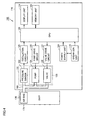
- Fig. 4 is a functional block diagram showing a configuration of the blood pressure monitor in the present embodiment. Next, with reference to Fig. 4, the configuration of main functional blocks of the blood pressure monitor in the present embodiment is described.
- an air system component for blood pressure measurement 131 is provided for supplying or discharging air through air tube 160 into or from air bag 171 contained in cuff 170.
- Air system component for blood pressure measurement 131 includes a pressure sensor 132 serving as a pressure detection unit detecting the pressure in air bag 171 and a pump 134 and a valve 135 that are components of inflation/deflation mechanism 133 for inflating/deflating air bag 171.
- an oscillation circuit 125, a pump drive circuit 126 and a valve drive circuit 127 are provided in association with air system component for blood pressure measurement 131.
- main-unit casing 110 there are provided a CPU (Central Processing Unit) 122 for centralized control and monitor of the components, a memory unit 123 for storing a program for allowing CPU 122 to perform a predetermined operation as well as various information such as a measured blood pressure value, display unit 114 for displaying various information including the result of measurement of a blood pressure, operation unit 115 operated for entering various instructions for measurement, and a power supply unit 124 for supplying electric power to CPU 122 and the functional blocks each.
- CPU 122 also serves as a blood pressure value calculation unit for calculating a blood pressure value.
- Pressure sensor 132 detects the pressure in air bag 171 (hereinafter referred to as "cuff pressure"), and outputs a signal according to the detected pressure to oscillation circuit 125.
- Pump 134 supplies air to air bag 171.
- Valve 135 opens/closes for keeping the pressure in air bag 171 or discharging the air in air bag 171.
- Oscillation circuit 125 outputs to CPU 122 a signal at an oscillation frequency according to the output value of pressure sensor 132.
- Pump drive circuit 126 controls drive of pump 134 based on a control signal provided from CPU 122.
- Valve drive circuit 127 controls opening/closing of valve 135 based on a control signal provided from CPU 122.
- Fig. 5 is a flowchart showing a flow of a process of measuring a blood pressure by the blood pressure monitor in the present embodiment.
- a description is given of the flow of the process of measuring a blood pressure by blood pressure monitor 100 in the present embodiment.
- a program in accordance with the flowchart is stored in advance in memory unit 123 as shown in Fig. 4.
- CPU 122 reads this program from memory unit 123 and executes the program to carry out the process of measuring a blood pressure.
- a user operates an operation button of operation unit 115 of blood pressure monitor 100 to turn on the power, and accordingly blood pressure monitor 100 is initialized (step S1). Then, when the state where a measurement can be taken is reached, CPU 122 starts driving pump 134 to gradually increase the cuff pressure of air bag 171 (step S2). In the process of gradually increasing the cuff pressure, when the cuff pressure reaches a predetermined level necessary for measuring the blood pressure, CPU 122 stops pump 134 and then gradually opens valve 135 which has been closed, so as to gradually discharge the air in air bag 171 and gradually decrease the cuff pressure (step S3). Regarding blood pressure monitor 100 in the present embodiment, the blood pressure value is measured in the process of decreasing the cuff pressure at a very low rate.
- CPU 122 calculates the blood pressure value (systolic pressure, diastolic pressure) through the known procedure (step S4). Specifically, in the stage where the cuff pressure is gradually decreased, CPU 122 extracts pulse-wave information based on the oscillation frequency obtained from oscillation circuit 125. Then, from the extracted pulse-wave information, the blood pressure value is calculated. As the blood pressure value is calculated in step S4, the calculated blood pressure value is displayed on display unit 114 (step S5).
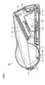
- Fig. 6 is a schematic cross-sectional view showing an internal structure of the blood pressure monitor in the present embodiment.
- the cuff, the air-tube portion connected to the cuff and the air system component for blood pressure measurement are not shown.
- Fig. 6 the internal structure of the blood pressure monitor in the present embodiment is described.
- a partition 110a is provided in main-unit casing 110.
- Partition 110a divides the space within main-unit casing 110 into an upper space and a lower space.
- a circuit board 121 where such components as CPU 122, memory unit 123, oscillation circuit 125, pump drive circuit 126 and valve drive circuit 127 as described above are provided.
- a component as a display support frame 114a for supporting display unit 114 formed of liquid crystal display is also provided.
- Winding unit 150 In the lower space, such components as a winding unit 150 allowing air tube 160 drawn out from main-unit casing 110 to be retracted into main-unit casing 110 as well as air system component for blood pressure measurement 131 (not shown) as described above are disposed.
- Winding unit 150 is formed of a disk-shaped assembly and is disposed horizontally in main-unit casing 110 so that the main surface of the winding unit is in parallel with the bottom surface of main-unit casing 110.
- Winding unit 150 is connected to air system component for blood pressure measurement 131 (not shown) by an intermediate air tube 136, and accordingly air bag 171 contained in cuff 170 is connected to air system component for blood pressure measurement 131 including inflation/deflation mechanism 133 via air tube 160 configured to be retractable into winding unit 150 and via intermediate air tube 136.
- a plurality of legs 116 protruding downwardly are provided.
- Legs 116 are components for stably mounting main-unit casing 110 of blood pressure monitor 100 on such a mount surface as table.
- a rubber member 116a is attached to the leading end of the legs each. Rubber member 116a is used for preventing, by friction, main-unit casing 110 from slipping to move on the mount surface while air tube 160 is drawn out from main-unit casing 110 or retracted into main-unit casing 110.
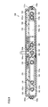
- Figs. 7 to 9 each show a structure of the winding unit provided to the blood pressure monitor in the present embodiment.
- Fig. 7 is a partially-cut-away plan view of the winding unit as seen from above and
- Fig. 8 is a bottom view of the winding unit as seen from below.
- Fig. 9 is a schematic cross-sectional view, along the line IX-IX shown in Figs. 7 and 8, of the winding unit.
- the structure of the winding unit mounted in the blood pressure monitor of the present embodiment is described.
- winding unit 150 provided in blood pressure monitor 100 of the present embodiment has a case body comprised of a lower case 151 and an upper case 152.
- Lower case 151 and upper case 152 each have a bottomed cylindrical outside shape. These lower case 151 and upper case 152 are combined to form a space in which various components are housed.
- Lower case 151 and upper case 152 are engaged with and secured to each other by means of a catch hook portion 151a and a catch receiving portion 152a provided on respective peripheral surfaces of these cases.
- a fixed block 154 is disposed between lower case 151 and upper case 152 and is fixed to the case body so that the block cannot be moved.
- a reel body 153 is disposed around the portion where fixed block 154 is positioned.
- Reel body 153 is rotatably supported by the case body.
- Reel body 153 has a bottomed cylindrical shape and has a housing 153a therein.
- Air tube 160 is guided along a predetermined route within winding unit 150 that is comprised of the above-described case body formed of lower case 151 and upper case 152, reel body 153 and fixed block 154.
- air tube 160 includes a wound portion 162, a fixed portion 163 and a freely movable portion 164 located between these wound portion 162 and fixed portion 163.
- Wound portion 162 is wound around an outer peripheral surface 153b of reel body 153 as described above
- fixed portion 163 is fixed by fixed block 154 as described above
- freely movable portion 164 is housed in housing 153a of reel body 153 as described above.
- air tube 160 housed in winding unit 150 includes fixed portion 163 and freely movable portion 164 that are formed of a single tube and includes wound portion 162 formed of a tube separate from the tube forming fixed portion 163 and freely movable portion 164. These two tubes are connected via a connector 167.
- Air tube 160 has a first free-movement end 165 that is the boundary between wound portion 162 and freely movable portion 164 and that is fixed to reel body 153 as well as a second free-movement end 166 that is the boundary between fixed portion 163 and freely movable portion 164 and that is fixed to fixed block 154.
- connector 167 is secured to reel body 153 with a screw 168 and thereby secures first free-movement end 165 to reel body 153, while second free-movement end 165 is directly secured to fixed block 154.
- fixed portion 163 of air tube 160 has one end connecting to freely movable portion 164 and the other end connected to fixed block 154.
- Wound portion 162 has one end connecting to freely movable portion 164 and the other end drawn out, from a draw-out opening 156 provided in the peripheral surface of the case body, to the outside of the case body.
- Reel body 153 is provided with a flange 153c1 and a plurality of guide projections 153c2 extending outwardly from outer peripheral surface 153b of the reel body.
- Flange 153c1 prevents wound portion 162 of air tube 160 that is wound around outer peripheral surface 153b of reel body 153 from contacting upper case 152.
- Guide projections 153c2 prevent wound portion 162 of air tube 160 that is wound around outer peripheral surface 153b of reel body 153 from contacting lower case 151.
- a helical spring 155 serving as a member applying elasticity is provided.
- Helical spring 155 has one end caught and fixed on a catch portion 153d provided to reel body 153, and the other end fixed to a substantially central portion of upper case 152.
- reel body 153 is biased all the time in the direction in which air tube 160 is wound up.
- a stopper 157 is pivotably attached by a pivot axis 157a.
- Stopper 157 has a portion facing upper case 152 and this portion is provided with a catch projection 157b.
- the inner surface of upper case 152 is provided with a groove 158 having a predetermined shape.
- Catch projection 157b is caught in groove 158 provided to upper case 152 described above, thereby forming a latch mechanism.
- This latch mechanism catches reel body 153 in stepwise manner in the direction in which reel body 153 is rotated, in order to keep the length of a drawn-out portion of air tube 160 in stepwise manner.
- This latch mechanism is available from any of well-known techniques (for example, the techniques disclosed in Japanese Patent Laying-Open Nos. 2002-226145 and 2002-274761 ). According to user's operation of drawing out air tube 160, the air tube is drawn out by a predetermined extent, and the drawn-out air tube may immediately be wound by the action of helical spring 155 as described above.
- Figs. 10A to 10C each illustrate a connection structure of the air tube provided at the first free-movement end as described above.
- air tube 160 is divided at this portion into portions that are connected by connector 167.
- Connector 167 is comprised of two members that are a first connector member 167A and a second connector member 167B.
- First connector member 167A has two opposing ends that are provided with respective connecting portions to which wound portion 162 of air tube 160 and freely movable portion 164 thereof are connected respectively.
- the pair of connecting portions has projections 167a that are provided respectively around the connecting portions for preventing the connected tube from being accidentally detached.
- the portion of the tube that is freely movable portion 164 is connected to connector 167 by means of this projection 167a only, so that this portion can be connected and disconnected relatively easily for assembly, repair, or the like.
- the portion of the tube that is wound portion 162 is rarely required to be removed from connector 167. Further, if this portion is accidentally detached, winding unit 150 has to be disassembled for connecting the portion again.
- this portion is more firmly secured to first connector member 167A by means of second connector member 167B.
- a projection 167b is provided for preventing accidental detachment. Between this projection 167b and projection 167a provided to first connector member 167A as described above, a part of the tube near the leading end of the tube portion that is wound portion 162 is held so as to prevent wound portion 162 from being accidentally detached from connector 167.
- the tube portion that is wound portion 162 and the tube portion that is freely movable portion 164 are connected by means of connector 167 in the following way.
- second connector member 167B is fit on the tube portion that is wound portion 162.
- first connector member 167A On respective connecting portions of first connector member 167A, the leading end of the tube portion that is wound portion 162 as well as the leading end of the tube portion that is freely movable portion 164 are fit.
- second connector member 167B fit in advance on the tube that is wound portion 162 is slid to be fixed to first connector member 167A.
- projection 167b provided to second connector member 167B goes beyond projection 167a provided to first connector member 167A. In this way, the connection structure as shown in Fig. 10C can be obtained.
- Figs. 11A and 11B show the shape of the fixed block as described above.
- Fig. 11A is a plan view and
- Fig. 11B is a side view of the fixed block.
- Figs. 12A and 12B show the state in which the air tube is connected to the fixed block.
- Fig. 12A is a plan view and Fig. 12B is a side view showing the state in which the air tube is connected to the fixed block.
- fixed block 154 has a connecting portion 154a provided to upwardly protrude and a connecting portion 154b provided to laterally protrude.
- connecting portion 154a provided to upwardly protrude
- connecting portion 154b provided to laterally protrude
- an end of intermediate air tube 136 connected to inflation/deflation mechanism 133 is connected to connecting portion 154b provided to laterally protrude
- an end of air tube 160 routed within winding unit 150 an end of fixed portion 163 is connected.
- These connecting portions 154a, 154b are communicated with each other by a communication path provided within fixed block 154. Accordingly, intermediate air tube 136 connected to fixed block 154 and air tube 160 communicate with each other.
- Fixed block 154 has an air-tube-disposed path 154c that receives air tube 160. At a predetermined position of air-tube-disposed path 154c, a projection 154d is provided. This projection 154d is used to fix, within air-tube-disposed path 154c, air tube 160 which is disposed in air-tube-disposed path 154c. Thus, fixed portion 163 of air tube 160 is formed.
- Such a fixing structure for air tube 160 as described above is employed to form, in the vicinity of projection 154d, second free-movement end 166 that is the boundary between fixed portion 163 and freely movable portion 164 of air tube 160, as shown in Fig. 12A.
- bias portion 154e is provided to protrude from air-tube-disposed path 154c.
- Bias portion 164e is a component that biases, in the way as described below, a portion that is a part of air tube 160 and that extends from second free-movement end 166 toward freely movable portion 164.
- a first straight line 181 (see Fig. 18 or 19) that overlaps the direction in which air tube 160 at second free-movement end 166 extends toward freely movable portion 164, the aforementioned portion of air tube 160 is biased in the direction opposite to the rotational direction (indicated by an arrow C shown in Figs.
- the rotational direction refers to the direction in which reel body 153 rotates as air tube 160 is drawn out
- position 153al refers to the position that is located on the inner peripheral surface of housing 153a and that is opposite to second free-movement end 166 in the direction in which air tube 160 at second free-movement end 166 extends toward freely movable portion 164.
- a guide portion 154f is provided at a portion adjacent to air-tube-disposed path 154c of fixed block 154.
- This guide portion 154f is a portion around which freely movable portion 164 of air tube 160 is wound in the state where air tube 160 is drawn out from winding unit 150, and is formed to have its outer peripheral surface 154f in the curved shape.
- second free-movement end 166 which is the boundary between fixed portion 163 of air tube 160 and freely movable portion 164 thereof, is disposed eccentrically with respect to rotational center O of reel body 153. Accordingly, bending (flexure) of freely movable portion 164 of air tube 160 is avoided even in the case where freely movable portion 164 of air tube 160 that is disposed to detour in housing 153a of reel body 153 so that it is freely movable in housing 153a is made long according to the length of the portion of air tube 160 that can be drawn out, in order to ensure at least a predetermined length of the portion of air tube 160 that can be drawn out of main-unit casing 110 of blood pressure monitor 100. This feature is described in detail together with behavior of air tube 160 within winding unit 150 when air tube 160 is drawn out.
- Figs. 13 to 17 illustrate behavior of the air tube within the winding unit when the air tube is drawn out from the winding unit configured as described above, showing respective states of stages at which the extent to which the tube is drawn out is gradually increased.
- freely movable portion 164 of air tube 160 is located to greatly detour within housing 153a provided in reel body 153. This is for the following reason. Freely movable portion 164 of air tube 160 has a part that is located relatively closer to wound portion 162 of air tube 160, and this part is located to abut the inner peripheral surface of housing 153a of reel body 153. Between the part abutting the inner peripheral surface and second free-movement end 166, greatly curved portions 164a, 164b are formed at some parts of air tube 160.
- air tube 160 is drawn out in the direction indicated by an arrow B as shown, and accordingly reel body 153 is rotated in the direction indicated by arrow C as shown. Since first free-movement end 165 of air tube 160 is fixed at a predetermined position of reel body 153, freely movable portion 164 is also moved within housing 153a as reel body 153 is rotated. At this time, since fixed portion 163 of air tube 160 is secured to fixed block 154, second free-movement end 166 does not move and stays at the position shown in Fig. 13. Accordingly, curved portion 164a formed at freely movable portion 164 of air tube 160 moves in the same direction as the rotational direction of reel body 153.
- air tube 160 has a portion extending from second free-movement end 166 toward freely movable portion 164 and this portion is biased in a predetermined direction by bias portion 154e provided to fixed block 154 as described above. Therefore, curved portion 164b formed at freely movable portion 164 does not move with the rotation of reel body 153 and thus stays substantially at the original position.
- blood pressure monitor 100 having winding unit 150 of the present embodiment is provided to avoid increased size of housing 153a provided within reel body 153 while a considerably large space where freely movable portion 164 of air tube 160 is movable can be ensured. Therefore, bending of freely movable portion 164 of air tube 160 can be prevented. In this way, winding unit 150 can be downsized while increase in size of main-unit casing 110 of blood pressure monitor 100 is eliminated. Therefore, the blood pressure monitor can be made compact while being excellent in terms of housing property.
- Figs. 18 and 19 specifically illustrate a preferred direction of eccentricity of the second free-movement end.
- the eccentric position of second free-movement end 166 is in a region S 1 shown in Fig. 18 or a region S2 shown in Fig. 19.
- region S1 the above-described effects can be obtained for any positions of second free-movement end 166 in this region.
- second free-movement end 166 is disposed in the range defined by region S2
- the effects can more remarkably be exhibited.
- specific conditions have to be met as described below.
- a portion that is a part of air tube 160 and that extends from second free-movement end 166 is curved, with respect to first straight line 181 that overlaps the direction (indicated by arrow D as shown) in which air tube 160 at second free-movement end 166 extends toward freely movable portion 164, in the direction opposite to the rotational direction (indicated by arrow C as shown) at position 153al.
- the rotational direction refers to the direction in which reel body 153 rotates when air tube 160 is drawn out
- position 153a1 refers to the position that is located on the inner peripheral surface of housing 153a and that is opposite to second free-movement end 166 in the direction (indicated by arrow D as shown) in which air tube 160 at second free-movement end 166 extends toward freely movable portion 164.
- housing 153a is divided into two regions along a second straight line 183 that is orthogonal to first straight line 181 as seen in the direction of the rotational axis of reel body 153 and that includes rotational center O of reel body 153
- second free-movement end 166 is disposed in the region opposite to the region in which position 153al on the inner peripheral surface of housing 153a is located, position 153al being opposite to second free-movement end 166 in the direction (indicated by arrow D as shown) in which air tube 160 at second free-movement end 166 extends toward freely movable portion 164, or disposed on second straight line 183.
- a straight line 182 shown in the drawings is a straight line that is parallel to first straight line 181 as seen in the direction of the rotational axis of reel body 153 and that includes rotational center O of reel body 153.
- region S 1 corresponds to one of the four regions into which the housing is divided along the above-described second straight line 183 and this straight line 182.
- second free-movement end 166 is disposed in region S 1. Accordingly, a sufficient space is ensured in which curved portion 164a of freely movable portion 164 that is located relatively closer to first free-movement end 165 moves, in the direction indicated by an arrow E as shown, as reel body 153 rotates. Therefore, in this region, bending of air tube 160 is not generated. Further, curved portion 164b which is generated at freely movable portion 164 as reel body 153 rotates does not move and disappears at the original position. Therefore, in this region, bending of air tube 160 does not occur. In this way, it can surely be prevented that the supply of air is hindered or that the air tube is broken.
- second free-movement end 166 in order to allow second free-movement end 166 to be disposed in region S2 shown in Fig. 19, in addition to the conditions as described above, the following condition has to be satisfied.
- a distance L between the position of second free-movement end 166 and position 153a1 on the inner peripheral surface of housing 153a that is opposite to second free-movement end 166 in the direction (indicated by arrow D as shown) in which air tube 160 at second free-movement end extends toward freely movable portion 164 is equal to or larger than a radius R of housing 153a.
- the oscillometric blood pressure monitor is described as an example. However, it would naturally be understood that the present invention is also applicable to a blood pressure monitor using the Korotkoff method.
- a signal line provided to connect the main-unit casing and the cuff may be integrated with the air tube into a composite line or these signal line and air tube may separately be provided.
- the latch mechanism is provided to the winding unit that fixes the rotation of the reel body in stepwise manner.
- frictional force may be exerted on the air tube to fix the air tube to allow the extent to which the air tube is drawn out to be an arbitrary extent.
Landscapes
- Health & Medical Sciences (AREA)
- Life Sciences & Earth Sciences (AREA)
- Cardiology (AREA)
- Vascular Medicine (AREA)
- Biomedical Technology (AREA)
- Heart & Thoracic Surgery (AREA)
- Physiology (AREA)
- Biophysics (AREA)
- Pathology (AREA)
- Engineering & Computer Science (AREA)
- Veterinary Medicine (AREA)
- Physics & Mathematics (AREA)
- Medical Informatics (AREA)
- Molecular Biology (AREA)
- Surgery (AREA)
- Animal Behavior & Ethology (AREA)
- General Health & Medical Sciences (AREA)
- Public Health (AREA)
- Ophthalmology & Optometry (AREA)
- Measuring Pulse, Heart Rate, Blood Pressure Or Blood Flow (AREA)
Applications Claiming Priority (1)
| Application Number | Priority Date | Filing Date | Title |
|---|---|---|---|
| JP2006006496A JP4876587B2 (ja) | 2006-01-13 | 2006-01-13 | 血圧計測装置 |
Publications (2)
| Publication Number | Publication Date |
|---|---|
| EP1808073A1 true EP1808073A1 (fr) | 2007-07-18 |
| EP1808073B1 EP1808073B1 (fr) | 2009-02-18 |
Family
ID=37891768
Family Applications (1)
| Application Number | Title | Priority Date | Filing Date |
|---|---|---|---|
| EP20070000247 Not-in-force EP1808073B1 (fr) | 2006-01-13 | 2007-01-08 | Dispositif de mesure de la pression artérielle |
Country Status (8)
| Country | Link |
|---|---|
| US (1) | US8075493B2 (fr) |
| EP (1) | EP1808073B1 (fr) |
| JP (1) | JP4876587B2 (fr) |
| KR (1) | KR100814547B1 (fr) |
| CN (1) | CN100496390C (fr) |
| DE (1) | DE602007000542D1 (fr) |
| RU (1) | RU2342066C2 (fr) |
| TW (1) | TW200733937A (fr) |
Cited By (1)
| Publication number | Priority date | Publication date | Assignee | Title |
|---|---|---|---|---|
| EP2455319A3 (fr) * | 2010-11-22 | 2013-06-19 | Telefonix, Inc. | Bobine de corde rétractable |
Families Citing this family (15)
| Publication number | Priority date | Publication date | Assignee | Title |
|---|---|---|---|---|
| JP5082963B2 (ja) * | 2008-03-19 | 2012-11-28 | オムロンヘルスケア株式会社 | 血圧計用カフおよびこれを備えた血圧計 |
| US20090247854A1 (en) * | 2008-03-27 | 2009-10-01 | Nellcor Puritan Bennett Llc | Retractable Sensor Cable For A Pulse Oximeter |
| US8961437B2 (en) * | 2009-09-09 | 2015-02-24 | Youhanna Al-Tawil | Mouth guard for detecting and monitoring bite pressures |
| JP5141650B2 (ja) | 2009-07-31 | 2013-02-13 | オムロンヘルスケア株式会社 | 血圧計 |
| CN103169464A (zh) * | 2012-12-24 | 2013-06-26 | 东莞得康医疗制品有限公司 | 便携式电子血压计及其测量方法 |
| CN104042201A (zh) * | 2013-03-15 | 2014-09-17 | 北京超思电子技术股份有限公司 | 便携式血压计 |
| US20150174619A1 (en) * | 2013-12-19 | 2015-06-25 | David Clements | System and Method for Cleaning and Retracting at least one Patient Monitoring Cable |
| CN104373747B (zh) * | 2014-11-07 | 2017-04-05 | 武汉法利普纳泽切割系统有限公司 | 大角度旋转双层管线防护装置 |
| CN104771151A (zh) * | 2015-03-23 | 2015-07-15 | 苏州锟恩电子科技有限公司 | 一种电缆线拉升式血压仪 |
| KR20170024985A (ko) | 2015-08-27 | 2017-03-08 | 삼성전자주식회사 | 무동력 가압부를 갖는 혈압계 |
| TWM547950U (zh) * | 2016-05-31 | 2017-09-01 | 宜強科技股份有限公司 | 不具加壓泵的穿戴式血壓量測裝置 |
| CN116692612A (zh) * | 2019-02-22 | 2023-09-05 | 胡斯华纳有限公司 | 软管箱组件 |
| CN110292442A (zh) * | 2019-07-03 | 2019-10-01 | 天津海迈医用科技有限公司 | 一种止血带吐带机的壳体装置 |
| AT523325A1 (de) * | 2019-12-20 | 2021-07-15 | Khu Peter | Lageranordnung zur Aufbewahrung von Spulgut |
| US11813046B2 (en) * | 2021-08-19 | 2023-11-14 | Ke Li | Method of cuff storage case for electronic blood pressure monitor |
Citations (9)
| Publication number | Priority date | Publication date | Assignee | Title |
|---|---|---|---|---|
| GB2114096A (en) * | 1982-02-04 | 1983-08-17 | Fumakilla Ltd | Retractable reel for electric fumigator |
| JPS62130606U (fr) | 1986-02-10 | 1987-08-18 | ||
| JPS63106280A (ja) | 1986-10-24 | 1988-05-11 | Kawaju Bosai Kogyo Kk | 長手体の巻取り装置 |
| JPS6419403U (fr) | 1987-07-22 | 1989-01-31 | ||
| WO2000031847A1 (fr) * | 1998-11-20 | 2000-06-02 | Burke Paul C | Enrouleur de cable rentrant miniature |
| US6199784B1 (en) * | 1999-07-19 | 2001-03-13 | Ceramate Technical Co., Ltd. | Automatically rewindable wire device |
| WO2001073911A1 (fr) * | 2000-03-24 | 2001-10-04 | Multicraft International | Enrouleur de cordon electrique et enrouleur de cordon electrique a montage horizontal pour aspirateur de menage |
| US6344025B1 (en) | 1999-02-19 | 2002-02-05 | Omron Corporation | Blood pressure monitor |
| EP1752090A2 (fr) * | 2005-08-12 | 2007-02-14 | Omron Healthcare Co., Ltd. | Appareil de mesure de la tension artérielle |
Family Cites Families (33)
| Publication number | Priority date | Publication date | Assignee | Title |
|---|---|---|---|---|
| US2629630A (en) * | 1951-01-15 | 1953-02-24 | Curis Kinard | Oxygen acetylene hose reel |
| US3621845A (en) * | 1969-05-14 | 1971-11-23 | Dennis G Oates | Sphygmomanometer |
| US3777840A (en) * | 1971-04-23 | 1973-12-11 | Botnick | Door mounted seat belt locking retractor |
| US3762411A (en) * | 1971-09-20 | 1973-10-02 | Aqua Fem Inc | Power aerated douche |
| US4417703A (en) * | 1981-11-19 | 1983-11-29 | Weinhold Dennis G | Quick retrieve cord reel |
| JPS62130606A (ja) | 1985-11-29 | 1987-06-12 | 井関農機株式会社 | コンバインの刈取判別装置 |
| IT1204220B (it) * | 1986-05-02 | 1989-03-01 | Uniflex Utiltime Spa | Carrello avvolgitubo |
| JPS6419403A (en) * | 1987-07-15 | 1989-01-23 | Hitachi Ltd | Process input device |
| JPH0397443A (ja) * | 1989-09-11 | 1991-04-23 | Terumo Corp | 血圧測定装置 |
| JP2582928B2 (ja) | 1990-05-30 | 1997-02-19 | 株式会社小糸製作所 | 自動車用灯具 |
| DE4108534A1 (de) * | 1991-03-15 | 1992-09-17 | Gore W L & Ass Gmbh | Wickelvorrichtung zum auf- und abwickeln einer leitung |
| US5236143A (en) * | 1991-10-23 | 1993-08-17 | Dragon Bradley P | Intravenous tubing retractor apparatus |
| JPH05317273A (ja) * | 1992-05-26 | 1993-12-03 | Omron Corp | 手首血圧計用カフ |
| CN1128648A (zh) | 1994-10-07 | 1996-08-14 | 欧姆龙株式会社 | 血压计 |
| JP2710594B2 (ja) * | 1995-09-20 | 1998-02-10 | 日本コーリン株式会社 | 血圧測定装置 |
| JPH10295654A (ja) * | 1997-05-02 | 1998-11-10 | Matsushita Electric Ind Co Ltd | 電子血圧計用枕 |
| JP2000083912A (ja) * | 1998-07-13 | 2000-03-28 | Omron Corp | 血圧計 |
| DE60024708T2 (de) * | 1999-04-28 | 2006-09-14 | Omron Healthcare Co., Ltd. | Elektronisches Sphygmomanometer mit einstellbarer Druckablassrate |
| CN1302275A (zh) * | 1999-04-28 | 2001-07-04 | 斯佩丘拉迪夫产品设计公司 | 可收回的电缆装置 |
| JP3452016B2 (ja) | 2000-02-17 | 2003-09-29 | オムロン株式会社 | 血圧計用カフ |
| KR200204867Y1 (ko) * | 2000-07-13 | 2000-12-01 | 세인전자주식회사 | 일체형 수납구조를 갖는 휴대형 혈압계 |
| RU2190345C2 (ru) | 2000-10-24 | 2002-10-10 | Борис Иосифович Синельников | Устройство для измерения артериального давления крови |
| US6731956B2 (en) * | 2001-03-26 | 2004-05-04 | Tania W. Hanna | Retractable cord for a mobile phone or other wireless device |
| DE10128337A1 (de) | 2001-06-12 | 2003-01-02 | Ibrahim Bogocli | Vorrichtung zum Bereistellen und Aufbewahren eines flexiblen Mittels |
| US7104491B2 (en) * | 2002-02-07 | 2006-09-12 | Vinding Donald R | Retractable reel for flexible tubing |
| RU2231967C2 (ru) | 2002-04-01 | 2004-07-10 | Коробов Вячеслав Иосифович | Устройство для измерения артериального давления |
| US6799808B1 (en) * | 2002-05-17 | 2004-10-05 | Corey J. Walters | Dump truck automatic mud flap retractor system |
| JP3818220B2 (ja) * | 2002-06-03 | 2006-09-06 | オムロンヘルスケア株式会社 | 手首式血圧計用カフ |
| DE10234627A1 (de) | 2002-07-29 | 2004-02-19 | Hartmann & König Stromzuführungs AG | Zugmittelspeicher |
| JP2005185756A (ja) | 2003-12-26 | 2005-07-14 | Omron Healthcare Co Ltd | 携帯型心電計 |
| JP3835461B2 (ja) * | 2004-04-20 | 2006-10-18 | オムロンヘルスケア株式会社 | 電子血圧計 |
| JP3815487B2 (ja) * | 2004-04-26 | 2006-08-30 | オムロンヘルスケア株式会社 | 血圧測定用帯の巻付け制御装置 |
| JP2006081668A (ja) * | 2004-09-15 | 2006-03-30 | Omron Healthcare Co Ltd | 血圧計用カフ |
-
2006
- 2006-01-13 JP JP2006006496A patent/JP4876587B2/ja not_active Expired - Lifetime
- 2006-11-22 KR KR1020060115684A patent/KR100814547B1/ko not_active Expired - Fee Related
- 2006-12-25 CN CNB2006101701697A patent/CN100496390C/zh active Active
-
2007
- 2007-01-08 EP EP20070000247 patent/EP1808073B1/fr not_active Not-in-force
- 2007-01-08 DE DE200760000542 patent/DE602007000542D1/de active Active
- 2007-01-09 TW TW096100783A patent/TW200733937A/zh unknown
- 2007-01-10 US US11/651,545 patent/US8075493B2/en active Active
- 2007-01-12 RU RU2007101333A patent/RU2342066C2/ru active
Patent Citations (9)
| Publication number | Priority date | Publication date | Assignee | Title |
|---|---|---|---|---|
| GB2114096A (en) * | 1982-02-04 | 1983-08-17 | Fumakilla Ltd | Retractable reel for electric fumigator |
| JPS62130606U (fr) | 1986-02-10 | 1987-08-18 | ||
| JPS63106280A (ja) | 1986-10-24 | 1988-05-11 | Kawaju Bosai Kogyo Kk | 長手体の巻取り装置 |
| JPS6419403U (fr) | 1987-07-22 | 1989-01-31 | ||
| WO2000031847A1 (fr) * | 1998-11-20 | 2000-06-02 | Burke Paul C | Enrouleur de cable rentrant miniature |
| US6344025B1 (en) | 1999-02-19 | 2002-02-05 | Omron Corporation | Blood pressure monitor |
| US6199784B1 (en) * | 1999-07-19 | 2001-03-13 | Ceramate Technical Co., Ltd. | Automatically rewindable wire device |
| WO2001073911A1 (fr) * | 2000-03-24 | 2001-10-04 | Multicraft International | Enrouleur de cordon electrique et enrouleur de cordon electrique a montage horizontal pour aspirateur de menage |
| EP1752090A2 (fr) * | 2005-08-12 | 2007-02-14 | Omron Healthcare Co., Ltd. | Appareil de mesure de la tension artérielle |
Cited By (1)
| Publication number | Priority date | Publication date | Assignee | Title |
|---|---|---|---|---|
| EP2455319A3 (fr) * | 2010-11-22 | 2013-06-19 | Telefonix, Inc. | Bobine de corde rétractable |
Also Published As
| Publication number | Publication date |
|---|---|
| RU2007101333A (ru) | 2008-07-20 |
| KR20070076398A (ko) | 2007-07-24 |
| JP4876587B2 (ja) | 2012-02-15 |
| RU2342066C2 (ru) | 2008-12-27 |
| KR100814547B1 (ko) | 2008-03-17 |
| CN100998502A (zh) | 2007-07-18 |
| JP2007185367A (ja) | 2007-07-26 |
| EP1808073B1 (fr) | 2009-02-18 |
| US20070197923A1 (en) | 2007-08-23 |
| CN100496390C (zh) | 2009-06-10 |
| US8075493B2 (en) | 2011-12-13 |
| DE602007000542D1 (de) | 2009-04-02 |
| TW200733937A (en) | 2007-09-16 |
Similar Documents
| Publication | Publication Date | Title |
|---|---|---|
| EP1808073B1 (fr) | Dispositif de mesure de la pression artérielle | |
| JP5811766B2 (ja) | 電子血圧計 | |
| CN1331438C (zh) | 血压测定装置 | |
| EP1752090B1 (fr) | Appareil de mesure de la tension artérielle | |
| BRPI0915602B1 (pt) | punho para dispositivo de informação de medição de pressão sanguínea e dispositivo de informação de medição de pressão sanguínea equipado com o mesmo | |
| JP5853587B2 (ja) | 電子血圧計 | |
| WO2010026868A1 (fr) | Sphygmomanomètre électronique fournissant des valeurs de mesure avec une fiabilité améliorée | |
| JP2011212159A (ja) | 手首式血圧計 | |
| CN101977548B (zh) | 血压计用袖带及具有该袖带的血压计 | |
| RU2556539C2 (ru) | Манжета устройства измерения информации об артериальном давлении и устройство измерения информации об артериальном давлении, снабженное упомянутой манжетой | |
| JP5536597B2 (ja) | 血圧計 | |
| JP2006255097A (ja) | 血圧計用カフおよび血圧計 | |
| JP2002102181A (ja) | カフ機構および電子血圧計 | |
| WO2011122124A1 (fr) | Dispositif de mesure de tension artérielle | |
| JP3835483B2 (ja) | 血圧計測装置 | |
| JP2013090824A (ja) | 電子血圧計 | |
| WO2011122126A1 (fr) | Dispositif de mesure de tension artérielle comprenant un brassard enveloppant un site de mesure | |
| CN222640463U (zh) | 一种多功能折叠型臂筒式血压计 | |
| CN113180626A (zh) | 血压检测组件、血压计及血压测量方法 | |
| JP2009225864A (ja) | 血圧計 | |
| JP2009225865A (ja) | 血圧計 | |
| JP4154693B2 (ja) | 血圧計 |
Legal Events
| Date | Code | Title | Description |
|---|---|---|---|
| PUAI | Public reference made under article 153(3) epc to a published international application that has entered the european phase |
Free format text: ORIGINAL CODE: 0009012 |
|
| AK | Designated contracting states |
Kind code of ref document: A1 Designated state(s): AT BE BG CH CY CZ DE DK EE ES FI FR GB GR HU IE IS IT LI LT LU LV MC NL PL PT RO SE SI SK TR |
|
| AX | Request for extension of the european patent |
Extension state: AL BA HR MK YU |
|
| 17P | Request for examination filed |
Effective date: 20080118 |
|
| AKX | Designation fees paid |
Designated state(s): DE ES FR GB IT NL |
|
| 17Q | First examination report despatched |
Effective date: 20080303 |
|
| GRAP | Despatch of communication of intention to grant a patent |
Free format text: ORIGINAL CODE: EPIDOSNIGR1 |
|
| GRAS | Grant fee paid |
Free format text: ORIGINAL CODE: EPIDOSNIGR3 |
|
| GRAA | (expected) grant |
Free format text: ORIGINAL CODE: 0009210 |
|
| AK | Designated contracting states |
Kind code of ref document: B1 Designated state(s): DE ES FR GB IT NL |
|
| REG | Reference to a national code |
Ref country code: GB Ref legal event code: FG4D |
|
| REF | Corresponds to: |
Ref document number: 602007000542 Country of ref document: DE Date of ref document: 20090402 Kind code of ref document: P |
|
| PG25 | Lapsed in a contracting state [announced via postgrant information from national office to epo] |
Ref country code: NL Free format text: LAPSE BECAUSE OF FAILURE TO SUBMIT A TRANSLATION OF THE DESCRIPTION OR TO PAY THE FEE WITHIN THE PRESCRIBED TIME-LIMIT Effective date: 20090218 Ref country code: ES Free format text: LAPSE BECAUSE OF FAILURE TO SUBMIT A TRANSLATION OF THE DESCRIPTION OR TO PAY THE FEE WITHIN THE PRESCRIBED TIME-LIMIT Effective date: 20090529 |
|
| NLV1 | Nl: lapsed or annulled due to failure to fulfill the requirements of art. 29p and 29m of the patents act | ||
| PLBE | No opposition filed within time limit |
Free format text: ORIGINAL CODE: 0009261 |
|
| STAA | Information on the status of an ep patent application or granted ep patent |
Free format text: STATUS: NO OPPOSITION FILED WITHIN TIME LIMIT |
|
| 26N | No opposition filed |
Effective date: 20091119 |
|
| REG | Reference to a national code |
Ref country code: FR Ref legal event code: ST Effective date: 20100930 |
|
| PG25 | Lapsed in a contracting state [announced via postgrant information from national office to epo] |
Ref country code: FR Free format text: LAPSE BECAUSE OF NON-PAYMENT OF DUE FEES Effective date: 20100201 |
|
| PG25 | Lapsed in a contracting state [announced via postgrant information from national office to epo] |
Ref country code: IT Free format text: LAPSE BECAUSE OF FAILURE TO SUBMIT A TRANSLATION OF THE DESCRIPTION OR TO PAY THE FEE WITHIN THE PRESCRIBED TIME-LIMIT Effective date: 20090218 |
|
| GBPC | Gb: european patent ceased through non-payment of renewal fee |
Effective date: 20110108 |
|
| PG25 | Lapsed in a contracting state [announced via postgrant information from national office to epo] |
Ref country code: GB Free format text: LAPSE BECAUSE OF NON-PAYMENT OF DUE FEES Effective date: 20110108 |
|
| REG | Reference to a national code |
Ref country code: DE Ref legal event code: R082 Ref document number: 602007000542 Country of ref document: DE Representative=s name: KILIAN KILIAN & PARTNER, DE Ref country code: DE Ref legal event code: R082 Ref document number: 602007000542 Country of ref document: DE Representative=s name: KILIAN KILIAN & PARTNER MBB PATENTANWAELTE, DE |
|
| PGFP | Annual fee paid to national office [announced via postgrant information from national office to epo] |
Ref country code: DE Payment date: 20210129 Year of fee payment: 15 |
|
| REG | Reference to a national code |
Ref country code: DE Ref legal event code: R119 Ref document number: 602007000542 Country of ref document: DE |
|
| PG25 | Lapsed in a contracting state [announced via postgrant information from national office to epo] |
Ref country code: DE Free format text: LAPSE BECAUSE OF NON-PAYMENT OF DUE FEES Effective date: 20220802 |