EP1808127A1 - Dispositif d imagerie par résonance magnétique nucléaire - Google Patents
Dispositif d imagerie par résonance magnétique nucléaire Download PDFInfo
- Publication number
- EP1808127A1 EP1808127A1 EP05799411A EP05799411A EP1808127A1 EP 1808127 A1 EP1808127 A1 EP 1808127A1 EP 05799411 A EP05799411 A EP 05799411A EP 05799411 A EP05799411 A EP 05799411A EP 1808127 A1 EP1808127 A1 EP 1808127A1
- Authority
- EP
- European Patent Office
- Prior art keywords
- imaging
- fov
- area
- examined subject
- magnetic resonance
- Prior art date
- Legal status (The legal status is an assumption and is not a legal conclusion. Google has not performed a legal analysis and makes no representation as to the accuracy of the status listed.)
- Granted
Links
Images





Classifications
-
- G—PHYSICS
- G01—MEASURING; TESTING
- G01R—MEASURING ELECTRIC VARIABLES; MEASURING MAGNETIC VARIABLES
- G01R33/00—Arrangements or instruments for measuring magnetic variables
- G01R33/20—Arrangements or instruments for measuring magnetic variables involving magnetic resonance
- G01R33/44—Arrangements or instruments for measuring magnetic variables involving magnetic resonance using nuclear magnetic resonance [NMR]
- G01R33/48—NMR imaging systems
- G01R33/54—Signal processing systems, e.g. using pulse sequences ; Generation or control of pulse sequences; Operator console
- G01R33/56—Image enhancement or correction, e.g. subtraction or averaging techniques, e.g. improvement of signal-to-noise ratio and resolution
- G01R33/563—Image enhancement or correction, e.g. subtraction or averaging techniques, e.g. improvement of signal-to-noise ratio and resolution of moving material, e.g. flow contrast angiography
- G01R33/56375—Intentional motion of the sample during MR, e.g. moving table imaging
-
- A—HUMAN NECESSITIES
- A61—MEDICAL OR VETERINARY SCIENCE; HYGIENE
- A61B—DIAGNOSIS; SURGERY; IDENTIFICATION
- A61B5/00—Measuring for diagnostic purposes; Identification of persons
- A61B5/70—Means for positioning the patient in relation to the detecting, measuring or recording means
- A61B5/704—Tables
-
- A—HUMAN NECESSITIES
- A61—MEDICAL OR VETERINARY SCIENCE; HYGIENE
- A61B—DIAGNOSIS; SURGERY; IDENTIFICATION
- A61B5/00—Measuring for diagnostic purposes; Identification of persons
- A61B5/72—Signal processing specially adapted for physiological signals or for diagnostic purposes
- A61B5/7271—Specific aspects of physiological measurement analysis
- A61B5/7285—Specific aspects of physiological measurement analysis for synchronizing or triggering a physiological measurement or image acquisition with a physiological event or waveform, e.g. an ECG signal
-
- G—PHYSICS
- G01—MEASURING; TESTING
- G01R—MEASURING ELECTRIC VARIABLES; MEASURING MAGNETIC VARIABLES
- G01R33/00—Arrangements or instruments for measuring magnetic variables
- G01R33/20—Arrangements or instruments for measuring magnetic variables involving magnetic resonance
- G01R33/44—Arrangements or instruments for measuring magnetic variables involving magnetic resonance using nuclear magnetic resonance [NMR]
- G01R33/48—NMR imaging systems
- G01R33/54—Signal processing systems, e.g. using pulse sequences ; Generation or control of pulse sequences; Operator console
- G01R33/56—Image enhancement or correction, e.g. subtraction or averaging techniques, e.g. improvement of signal-to-noise ratio and resolution
- G01R33/563—Image enhancement or correction, e.g. subtraction or averaging techniques, e.g. improvement of signal-to-noise ratio and resolution of moving material, e.g. flow contrast angiography
- G01R33/5635—Angiography, e.g. contrast-enhanced angiography [CE-MRA] or time-of-flight angiography [TOF-MRA]
-
- G—PHYSICS
- G01—MEASURING; TESTING
- G01R—MEASURING ELECTRIC VARIABLES; MEASURING MAGNETIC VARIABLES
- G01R33/00—Arrangements or instruments for measuring magnetic variables
- G01R33/20—Arrangements or instruments for measuring magnetic variables involving magnetic resonance
- G01R33/44—Arrangements or instruments for measuring magnetic variables involving magnetic resonance using nuclear magnetic resonance [NMR]
- G01R33/48—NMR imaging systems
- G01R33/54—Signal processing systems, e.g. using pulse sequences ; Generation or control of pulse sequences; Operator console
- G01R33/56—Image enhancement or correction, e.g. subtraction or averaging techniques, e.g. improvement of signal-to-noise ratio and resolution
- G01R33/567—Image enhancement or correction, e.g. subtraction or averaging techniques, e.g. improvement of signal-to-noise ratio and resolution gated by physiological signals, i.e. synchronization of acquired MR data with periodical motion of an object of interest, e.g. monitoring or triggering system for cardiac or respiratory gating
- G01R33/5673—Gating or triggering based on a physiological signal other than an MR signal, e.g. ECG gating or motion monitoring using optical systems for monitoring the motion of a fiducial marker
-
- G—PHYSICS
- G01—MEASURING; TESTING
- G01R—MEASURING ELECTRIC VARIABLES; MEASURING MAGNETIC VARIABLES
- G01R33/00—Arrangements or instruments for measuring magnetic variables
- G01R33/20—Arrangements or instruments for measuring magnetic variables involving magnetic resonance
- G01R33/44—Arrangements or instruments for measuring magnetic variables involving magnetic resonance using nuclear magnetic resonance [NMR]
- G01R33/48—NMR imaging systems
- G01R33/54—Signal processing systems, e.g. using pulse sequences ; Generation or control of pulse sequences; Operator console
- G01R33/56—Image enhancement or correction, e.g. subtraction or averaging techniques, e.g. improvement of signal-to-noise ratio and resolution
- G01R33/567—Image enhancement or correction, e.g. subtraction or averaging techniques, e.g. improvement of signal-to-noise ratio and resolution gated by physiological signals, i.e. synchronization of acquired MR data with periodical motion of an object of interest, e.g. monitoring or triggering system for cardiac or respiratory gating
- G01R33/5676—Gating or triggering based on an MR signal, e.g. involving one or more navigator echoes for motion monitoring and correction
-
- G—PHYSICS
- G01—MEASURING; TESTING
- G01R—MEASURING ELECTRIC VARIABLES; MEASURING MAGNETIC VARIABLES
- G01R33/00—Arrangements or instruments for measuring magnetic variables
- G01R33/20—Arrangements or instruments for measuring magnetic variables involving magnetic resonance
- G01R33/44—Arrangements or instruments for measuring magnetic variables involving magnetic resonance using nuclear magnetic resonance [NMR]
- G01R33/48—NMR imaging systems
- G01R33/483—NMR imaging systems with selection of signals or spectra from particular regions of the volume, e.g. in vivo spectroscopy
- G01R33/4833—NMR imaging systems with selection of signals or spectra from particular regions of the volume, e.g. in vivo spectroscopy using spatially selective excitation of the volume of interest, e.g. selecting non-orthogonal or inclined slices
-
- G—PHYSICS
- G01—MEASURING; TESTING
- G01R—MEASURING ELECTRIC VARIABLES; MEASURING MAGNETIC VARIABLES
- G01R33/00—Arrangements or instruments for measuring magnetic variables
- G01R33/20—Arrangements or instruments for measuring magnetic variables involving magnetic resonance
- G01R33/44—Arrangements or instruments for measuring magnetic variables involving magnetic resonance using nuclear magnetic resonance [NMR]
- G01R33/48—NMR imaging systems
- G01R33/54—Signal processing systems, e.g. using pulse sequences ; Generation or control of pulse sequences; Operator console
- G01R33/56—Image enhancement or correction, e.g. subtraction or averaging techniques, e.g. improvement of signal-to-noise ratio and resolution
- G01R33/563—Image enhancement or correction, e.g. subtraction or averaging techniques, e.g. improvement of signal-to-noise ratio and resolution of moving material, e.g. flow contrast angiography
- G01R33/56375—Intentional motion of the sample during MR, e.g. moving table imaging
- G01R33/56383—Intentional motion of the sample during MR, e.g. moving table imaging involving motion of the sample as a whole, e.g. multistation MR or MR with continuous table motion
Definitions
- the present invention relates to a nuclear magnetic resonance imaging apparatus (hereinafter, referred to as "MRI apparatus") that measures an NMR signal emitted from hydrogen, phosphor, and the like within a subject to be examined and visualizes a nuclear density distribution, a relaxation time distribution, and the like.
- MRI apparatus nuclear magnetic resonance imaging apparatus
- it relates to a method to suppress an artifact caused by a living body in the MRI apparatus employing an imaging method, referred to as "moving bed imaging method".
- This moving bed imaging method acquires an image of a portion being wide in a body axis direction, by acquiring the NMR data while continuously moving a table on which the examined subject is laid.
- a method that acquires an image while moving a table continuously (see Patent document 1).
- moving bed imaging there are also proposed several means such as using a signal processing to recover image degradation that occurs because the imaging is performed while moving the bed, and limiting a velocity at which the bed is moved to a low speed so that the image degradation may not occur.
- the patent document 1 further proposes that in a full-body imaging by MRA (magnetic resonance angiography), a bed moving velocity is made higher for a body trunk whereas it is made slower for lower extremities, so as to perform the imaging with consideration for the imaging area to coincide with a region where a contrast agent is flowing through blood vessels.
- MRA magnetic resonance angiography
- a living body Since a living body has a cardiac beat and respiratory movement, those may degrade an image quality when an image of the heart or the liver is acquired. In order to avoid this image degradation due to such movements of the living body, cardiac triggering, pulse triggering, and respiratory gating are widely employed.
- cardiac triggering, pulse triggering, and respiratory gating are widely employed.
- a method to eliminate a body motion artifact that occurs due to the movement of the examined subject while one piece of MR image is generated there is proposed a method in which a respiratory motion is monitored by using an external breath sensor or a navigator echo, for instance, and measuring is performed only when a position of the examined subject undergoes a predetermined displacement.
- the movement of the bed is turned ON and OFF in response to the biological gating signal, in order to avoid the occurrence of such artifact.
- the movement is restarted from the position which is the same as the position before gating off, whereby the imaging positions can be rendered continuous in a series of data acquisition.
- An object of the present invention is to reduce a load on the examined subject due to a change of moving velocity of the transport unit, and further provide an image that is effective for diagnosis, responding to variations in conditions while imaging a wide area, in the MRI apparatus employing the moving bed imaging method.
- a field of view (FOV) (signal acquisition area) on the examined subject moves in a direction opposite to the direction of the bed movement, both moving at the same velocity.
- FOV field of view
- the present invention has achieved the above object by controlling the FOV (signal acquisition area) to move at a speed different from the bed movement.
- the present invention is directed to a nuclear magnetic resonance imaging method that acquires an image of an imaging region of the examined subject, in a static magnetic field space of a nuclear magnetic resonance imaging apparatus provided with an FOV being desirable, the imaging region being wider than the FOV, while moving the transport unit having the examined subject thereon including, a step (1) that moves the examined subject so that the imaging region of the examined subject passes through the space for imaging, a step (2) that relatively displaces the FOV with respect to the static magnetic field space, in response to information obtained from the examined subject during at least a part of a period when the examined subject is being moved, a step (3) that executes an imaging pulse sequence while the examined subject is being moved, and collects NMR signals from the examined subject, and a step (4) that reconstructs an image of the wide imaging region of the examined subject, by using the NMR signals.
- the information obtained from the examined subject may be biological information directly acquired from the examined subject such as an electrocardiograph and sphygmograph, for example, further including all the other information that can be obtained regarding the examined subject, such as positional information according to body motion and shifting of the examined subject, and information obtained from the nuclear magnetic resonance signal.
- the information obtained from the examined subject is biological information detected from the examined subject, and a moving velocity of the FOV for the examined subject is controlled to be different from each other between in a first period and in a second period while acquiring an image of the imaging region, in response to this biological information.
- a direction of the relative displacement is controlled to be different from each other between in the first period and in the second period.
- the nuclear magnetic resonance imaging method includes a step (5) that configures settings for a first area and a second area within the imaging region, prior to the step (3) that collects the NMR signals, further includes in the step (2) that relatively displaces the FOV, a step (6) that acquires positional information of the FOV for the examined subject, the information obtained from the examined subject is information indicating reaching that the FOV has reached each of the areas, and a moving velocity of the FOV for the examined subject is controlled to be different from each other between in the first area and in the second area, in response to the information indicating the reaching.
- the direction of the relative displacement is controlled to be different from each other in the first area and in the second area.
- imaging of at least a part of the imaging region for instance, includes a synchronous imaging by using the biological information
- the imaging is executed in the first period in response to the biological information
- the imaging is suspended in the second period in response to the biological information
- the direction of the relative displacement is opposite to the moving direction of the examined subject in the first period
- the direction of the relative displacement is the same as the moving direction of the examined subject in the second period.
- the biological information is acquired from a biological signal, for example, obtained from at least one of the electrocardiograph, the sphygmograph, and a body motion monitor
- a moving velocity of the transport unit is determined by a total imaging time including the first period and the second period and a distance the transport unit has traveled for acquiring an image of the imaging region
- the moving velocity of the FOV for the examined subject within the first period is determined by the total imaging time when no synchronous imaging is performed, and a distance that the transport unit has traveled for acquiring the image of the imaging region
- the imaging is executed from a position of the FOV at the point when the imaging is suspended, and in the second period, the moving velocity of the FOV for the examined subject is set to zero and the position of the FOV for the examined subject is not moved.
- imaging of the second area includes, for example, collecting of the NMR signals required for reconstructing a subject image, and collecting of the NMR signals required for detecting a body motion of the examined subject, and in the step (2), the moving velocity of the FOV for the examined subject is controlled to be lower in the second area than in the first area.
- an imaging condition in the first area is set to be different from the imaging condition in the second area, for example, and in the step (2) that relatively displaces the FOV, the moving velocity of the FOV for the examined subject is controlled to be different from each other between in the first area and in the second area, in response to each of the imaging conditions.
- the imaging conditions are set such that the second area should have a spatial resolution higher than the first area, and in the step (2) that relatively displaces the FOV, the moving velocity of the FOV for the examined subject is controlled to be lower in the second area than in the first area.
- the imaging condition for the second area is set in such a manner that at least one of a slice number, a phase encoding number, and a slice encoding number is increased relative to the imaging condition for the first area.
- the imaging conditions are set such that the second area should have a higher SN than the first area, and in the step (2) that relatively displaces the FOV, the moving velocity of the FOV for the examined subject is controlled to be lower in the second area than in the first area.
- the imaging conditions are set in such a manner that a number of averaging the nuclear magnetic resonance signals is increased in the imaging condition for the second area, relative to the imaging condition for the first area.
- the imaging conditions are set in such a manner that a size of the FOV in the first area and a size of the FOV in the second area are different from each other.
- the step (3) that collects the NMR signals includes an imaging using a contrast agent
- the step (5) that configures settings of each of the areas the first area and the second area are configured in such a manner that in the second area, the contrast agent moves at a velocity lower than the first area
- the step (2) that relatively moves the FOV the moving velocity of the FOV for the examined subject is controlled to be lower in the second area than in the first area.
- the nuclear magnetic resonance imaging method includes a step (7) that obtains a mean flow velocity of the contrast agent within the imaging region, prior to the step (5) that configures settings of each of the areas, in the step (1) that moves the examined subject, the moving velocity of the transport unit is assumed as the mean flow velocity, and in the step (2) that relatively displaces the FOV, in order that the moving velocity of the FOV for the examined subject accords with the moving velocity of the contrast agent, a moving direction of the FOV for the examined subject is set to be opposite to the moving direction of the examined subject in the first area, and the moving direction of the FOV for the examined subject is made to be the same as the moving direction of the examined subject in the second area.
- the first area and the second area are configured in such a manner that the second area is set in an area where a body axis direction of the examined subject and the moving direction of the examined subject form a larger angle than in the first area, and in the step (2) that relatively displaces the FOV, the moving velocity of the FOV for the examined subject in the moving direction of the examined subject is controlled to be lower in the second area than in the first area.
- the FOV in the nuclear magnetic resonance imaging method, in the step (2) that relatively displaces the FOV, for example, the FOV is moved along the body axis direction, and the moving velocity of the FOV in the body axis direction is made approximately identical between the first area and the second area.
- a high-frequency magnetic field is applied for exciting the FOV
- a frequency of the high-frequency magnetic field is controlled so as to control the relative displacement of the FOV
- the moving velocity of the examined subject is kept constant during a period for acquiring an image of the imaging region.
- the moving velocity of the examined subject is controlled to be different from each other between in the first period and in the second period.
- step (4) that reconstructs the image for example, an image of a part of the imaging region is reconstructed based on the NMR signals that have been obtained so far within at least a part of the period for acquiring an image of the imaging region.
- the nuclear magnetic resonance imaging apparatus includes, a transport unit that transports a subject to be examined within a static magnetic field space including a desired FOV, an information obtaining unit that obtains information from the examined subject, a magnetic field application unit that applies a high-frequency magnetic field and a gradient magnetic field to the examined subject, a control means that controls the transport unit and the magnetic field application unit, and a signal processing unit that receives NMR signals generated from the examined subject to construct an image, wherein, in the nuclear magnetic resonance imaging apparatus that acquires the NRM signals while the examined subject is moved by the transport unit, and acquires an image of an imaging region wider than the FOV, the control unit controls the magnetic field application unit in such a manner that the FOV is relatively displaced with respect to the static magnetic field space, in response to the information from the examined subject, during at least a part of the period when the examined subject is moving.
- the information obtaining unit that obtains information from the examined subject, obtains biological information from the examined subject, and the control unit controls the magnetic field application unit, in response to the biological information, in such a manner that the moving velocity of the FOV for the examined subject is made different from each other between in a first period and in a second period, while an image of the imaging region is acquired.
- the information obtaining unit that obtains information from the examined subject, further obtains positional information of the FOV for the examined subject, and finds information indicating reaching that the FOV has reached the first area and the second area within the imaging region configured in advance, and the control unit controls the magnetic field application unit, in response to the information indicating the reaching, in such a manner that the moving velocity of the FOV for the examined subject is made different from each other between in the first period and in the second period.
- the information obtaining unit that obtains the biological information is at least one of an electrocardiograph, a sphygmograph, and a body motion monitor, and the control unit controls the magnetic field application unit in such a manner that the imaging is performed during the first period in response to the biological information, and the imaging is suspended during the second period in response to the biological information.
- the unit that obtains the positional information of the FOV includes an encoder provided on the transport unit, and obtains the positional information of the FOV on the examined subject based on information from the encoder and a frequency of the high-frequency magnetic field.
- imaging is performed while the subject to be examined is moved, and the FOV is relatively displaced with respect to the static magnetic field space while the examined subject (i.e., transport unit) is moved. Therefore, a load on the examined subject is reduced, which is caused by fluctuations in the moving velocity of the transport unit, and further, variations in conditions while imaging a wide area are addressed, thereby providing an image effective for diagnosis.
- a load on the examined subject is reduced, which is caused by fluctuations in the moving velocity of the transport unit, and further, variations in conditions while imaging a wide area are addressed, thereby providing an image effective for diagnosis.
- a synchronous imaging even when the imaging is turned ON/OFF according to a gating signal, it is possible to maintain continuity of an area from which a signal is acquired, and an image without artifact can be obtained.
- various imaging is available such as obtaining an image of high spatial resolution and an image of multiple slices, according to a request from a user.
- the imaging utilizing a contrast agent it is possible to acquire an image following a moving velocity of the contrast agent.
- a moving velocity of the transport unit can be configured with consideration given to a total imaging time. Therefore, even if suspension or restarting of imaging and/or fluctuations in the imaging time occur due to various imaging, an effect caused by heterogeneity of the magnetic field can be suppressed to a negligible degree, and a favorable image can be acquired.
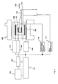
- FIG. 1 illustrates an overview of an MRI apparatus to which the present invention is applied.
- This MRI apparatus is provided with a magnet 102 that generates a static magnetic field in a space into which a subject to be examined 101 is placed, a gradient magnetic field coil 103 that generates a gradient magnetic field within this space, an RF coil 104 that generates a high-frequency magnetic field in an imaging area of the examined subject, an RF probe 105 that detects nuclear magnetic resonance (MR) signals that are generated by the examined subject 101, and a bed 112 for introducing the examined subject 101 into to the static magnetic field space.
- a top panel of the bed 112 is provided with a detection unit, e.g., an encoder, so as to detect a position and a moved distance of the bed.
- a detection unit e.g., an encoder
- the gradient magnetic field coil 103 is made up of gradient magnetic field coils respectively in three directions (X, Y, Z) orthogonal to one another, and each generates a gradient magnetic field in response to a signal from a gradient magnetic field power source 109. According to a manner how these gradient magnetic fields are applied, an imaging section of the examined subject can be determined, and positional information is given to the MR signal.
- the RF coil 104 generates a high-frequency magnetic field in response to a signal from an RF transmitter 110.
- a signal from the RF probe 105 is detected by the signal detector 106 and the detected signal is subjected to a signal processing in the signal processor 107. Then, it is calculated to be converted into an image signal.
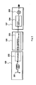
- FIG. 2 illustrates details of the signal detector 106 and the signal processor 107.
- the signal detector 106 is made up of an AD conversion/quadrature detection circuit 203, and an NMR signal amplified by a preamplifier 202 of RF receiving coil 201 is subjected to quadrature detection by using a reference signal from a high-frequency generating circuit of the RF transmitter 110, as well as subjected to AD conversion be converted into two series of data, and then the converted data is passed to the signal processor 107.
- the signal processor 107 performs processing such as Fourier transformation, correction, and synthesis of data as appropriate, so as to reconstruct an image. The image is displayed on the display 108.
- the gradient magnetic field power source 109, the RF transmitter 110, and the signal detector 106 are controlled by a controller 111.
- a control time chart is generally referred to as "pulse sequence", and various pulse sequences (imaging sequences), which are determined depending on a way how to perform imaging, are previously stored in a form of program, in a storage not illustrated.
- the controller 111 is provided with an input device (user interface: UI) for selecting an imaging sequence and for inputting an imaging parameter, and the like.
- the bed 112 is movable in the direction indicated by an arrow 113 in the figure, and it is driven by a bed controller 114.
- the bed controller 114 follows a command from the controller 111 to move the bed 112 in a manner to be consistent with execution of an imaging sequence.
- a moving velocity of the bed for example, a velocity to be moved in the direction from the head to feet, is 0.5 cm per second to 2.0 cm per second, typically.
- the controller 111 inputs a signal from a monitoring machine 115 that monitors a biological signal from the examined subject 101, and controls execution of the imaging sequence based on the biological signal.
- the monitoring machine 115 monitors, for example, a beat, a pulse wave, an electrocardiographic waveform, and a respiratory motion, and the like, and the monitored data is converted into an electrical signal or an optical signal. Then, the converted data is transmitted to the controller 111 in real time.
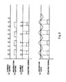
- FIG. 3 shows an example of gating signal in the case where the double gating is employed.
- (a) indicates a signal (R wave) from the electrocardiograph
- (b) indicates a position signal from the respiratory motion sensor
- (c) is AND signal of (a) and (b)
- (d) indicates a gating signal.
- the controller 111 controls imaging ON/OFF by using the gating signal.
- the gating signal turns the imaging ON when the signal from the electrocardiograph is placed between R-wave and R-wave and the position signal from the respiratory motion sensor is within a predetermined range of the examined subject. At all other cases, the imaging is turned OFF.
- FIG. 4 illustrates an example of the imaging sequence that is executed in the MRI apparatus according to the present invention.
- This imaging sequence is a generic 3D gradient echo sequence, and it firstly applies a high-frequency pulse 401 simultaneously with a slice selective gradient magnetic field 402 so that a predetermined area of the examined subject is excited.
- a slice (slab) is assumed as a cross section being parallel with the body axis of the examined subject.
- a slice encoding gradient magnetic field pulse 403 and a phase encoding gradient magnetic field pulse 404 are applied.
- a readout gradient magnetic field pulse 405 is applied and an echo signal 406 is measured at a point of time after TE time 407 has elapsed since the application of the high-frequency pulse 401.
- Such measurement as described above is repeated every repetition time 408, while varying intensity of the slice encoding gradient magnetic field pulse 403 and the phase encoding gradient magnetic field pulse 404.
- echo signals required for reconstructing one piece of 3D image are measured.
- the slice encoding number and the phase encoding number are selected as a combination of values such as 32, 64, 128, 256, and 512, generally for one piece of 3D image.
- Each echo signal is obtained as a time-series signal made up of sampling data items generally the number of which is 128, 256, 512, or 1024. This data is subjected to 3D Fourier transformation considering a displacement of k-spatial data, whereby 3D image data can be obtained.
- An image reconstructing method is the same as the image reconstructing method in a publicly known moving bed imaging method. A concept of this method will be explained briefly.
- imaging is continuously performed assuming that a plane parallel to the body axis of the examined subject 1101 is an imaging cross section, and a direction parallel to the moving direction of the bed 102, i.e., the examined subject (the direction indicated by an arrow in the figure) is a readout direction Gr.
- the bed 1102 moves in the arrow direction using the point P as a starting point (0)
- the FOV 1103 is relatively displaced with respect to the examined subject 1101
- the moving velocity of the FOV corresponds to the moving velocity of the bed.
- the data (ky-x space data) is displaced in the readout direction (x direction) as shown in FIG. 11 (b), and finally, it becomes data that fills the ky-x space. Therefore, by subjecting the data filling the ky-x space to the Fourier transformation, an image covering the total length in the x direction can be obtained.
- COR (coronal) section and/or TRS (transverse) section are typically used, and a moving direction of the bed is a slice direction for the TRS section, and it is a readout gradient magnetic field direction for the COR section.
- any methods may be applicable, and further it is not limited to these publicly known methods.
- a sequence of gradient echo system is shown, but other imaging sequence may be employed.
- DWI diffusion Weighted Imaging
- EPI Echo Planar Imaging
- FSE Flust Spin Echo
- coronary imaging and a general T2 weighted image.
- 3D sequence not only 3D sequence but also 2D sequence or multi-slice sequence is applicable. Further, radial scanning is also applicable.
- the MRI apparatus features a synchronous imaging control.
- Control of the asynchronous imaging is similar to the conventional moving bed imaging method, and a time required for imaging a wide imaging region along the moving direction of the bed is calculated to determine a moving velocity Vb of the bed based on this imaging time.
- the moving velocity Vb of the bed is configured to be a velocity obtained by dividing the total length of the imaging region by the imaging time.
- the bed moving velocity Vb corresponds to the moving velocity Vf of the FOV position on the examined subject, and it is as shown in FIG. 12.
- the horizontal axis represents a time and the vertical axis represents a position.
- Two lines respectively represent a change of the bed position and a change of the FOV position during the imaging time.
- zigzag lines in the center schematically illustrate a status of imaging during the imaging time, indicating a change of encoding amount.
- the imaging pulse sequence is assumed as 2D sequence, the fine zigzag line indicates every one encoding step, and the zigzag line with a large spacing indicates a change of the encoding amount every imaging of one FOV in the phase encoding direction.
- the imaging pulse sequence is assumed as 3D sequence, the fine zigzag line indicates every one slice-encoding step, and the zigzag line with a large spacing indicates a change of the encoding amount every imaging of one FOV in the slice encoding direction.
- a relationship between the FOV 1103 and the examined subject 1101 is indicated. In this asynchronous imaging, a position of the FOV 1103 with respect to the center of the static magnetic field may not change.
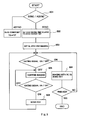
- FIG. 5 illustrates a flow of control performed in the synchronous imaging.
- a ratio of the imaging velocity of the synchronous imaging is set, relative to the imaging velocity in the case where the synchronous imaging is not performed (in the case of asynchronous imaging) (step 502).
- the imaging sequence is decided, the imaging time of the asynchronous imaging is automatically decided according to the TR, the encoding number, and the number of FOV. Therefore, relative to this imaging time for the asynchronous imaging, it is determined how much longer the synchronous imaging time is needed to be, that is, to what extent the imaging velocity is reduced.
- Such velocity ratio R as described above may be automatically calculated by receiving biological gating signals for a predetermined period of time prior to starting the imaging, and using ON/OFF signals therefrom.
- the bed moving velocity Vb and the moving velocity Vf of the imaging area (FOV) in a coordinate system of the examined subject are determined (step 503).
- Vb Vf.
- the bed moving velocity in the asynchronous imaging is assumed as V0
- the imaging time T0 of the asynchronous imaging is 60 seconds and the imaging time Tg of the synchronous imaging is 200 seconds
- the bed moving velocity at the time of asynchronous imaging is 1 cm per second
- imaging is performed by reducing the bed moving velocity to 0.3( ⁇ 1 cm/s ⁇ x 60/200) during the synchronous imaging.
- the imaging is suspended (step 505).
- the bed is kept moving even while the imaging is suspended. Therefore, when the gating signal is turned ON next, the FOV in the apparatus coordinate system is controlled such that the position in the subject coordinate system should become identical to the FOV position when the imaging was suspended, and obtaining of an echo signal is started (step 506).
- the controlling of the FOV as described above can be implemented by controlling the FOV position in the apparatus coordinate system, similar to the aforementioned movement of the FOV while the imaging is performed. For example, as for the slice direction, the slice gradient magnetic field and the excited RF pulse frequency are controlled, thereby controlling the FOV position in the apparatus coordinate system. Accordingly, in the subject coordinate system, the imaging can be performed on sequential positions, irrespective of ON/OFF status of the imaging.
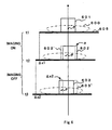
- FIG. 6 illustrates a positional relationship among the FOV, the bed, and the examined subject in the imaging as described above.
- the arrow in the vertical direction indicates a static magnetic field direction passing through the center of the static magnetic field, and it is assumed that the bed 605 moves in a direction orthogonal to the static magnetic field direction.
- the center of the FOV 601 corresponds to the center of the static magnetic field, and it also corresponds to a given point P of the examined subject 600.
- the bed 605 moves at a moving velocity Vb, and its moved distance becomes ⁇ x1.
- the moving velocity Vb of the bed 605 is equal to the moving velocity V of the FOV, a position of the FOV with respect to the center of the static magnetic field is not changed. Therefore, at the point of time t2, the FOV reaches the position 602' indicated by a dotted line. However, since Vf > Vb is defined in the present embodiment, the FOV moves to the position 602 indicated by a solid line. In other words, the position is off the center by ⁇ , which is decided by a difference between Vb and Vf. Next, even if the imaging is turned OFF at the point t2 and it is restarted at the point t3, the bed 605 keeps moving at a constant velocity even during this OFF period.
- the examined subject 600 is also shifted.
- the imaging is restarted at the FOV 603' that is identical to the FOV 602 at the point of t2, there is a loss of data corresponding to the bed moved distance ⁇ x2. Accordingly, it is controlled so that the position of FOV in the apparatus coordinate system is shifted to the position 603, and the FOV on the examined subject 600 becomes the same as the FOV at the point of t2.
- the position of P in the FOV 602 corresponds to the position P in the FOV 603.
- FIG. 7 A relationship between the FOV position (a position in the examined subject coordinate system) and the bed position in the total imaging process is shown in FIG. 7.
- the vertical axis indicates a position of the bed in the bed moving direction
- the horizontal axis indicates a time.
- the dotted line represents the position of the bed
- the solid line represents the FOV position in the synchronous imaging
- the alternate long and short dash line represents the FOV position in the asynchronous imaging.
- the alternate long and short dash line and an inclined part of the solid line are parallel to each other, representing, respectively, the FOV position in the asynchronous imaging and the FOV position in the asynchronous imaging.
- the imaging velocity is identical in the both cases.
- Reference mark (a) schematically indicates a biological gating signal and reference mark (b) schematically indicates variation of the encoding amount in accordance with the imaging.
- a fine zigzag line indicates each one encoding step
- a zigzag line having a large spacing indicates a change of the encoding amount in the phase encoding direction every imaging of one FOV.
- the encoding amount represents only the encoding amount in the phase encoding direction.
- the fine zigzag line indicates each one slice-encoding step
- the zigzag line having a large spacing indicates a change of the encoding amount in the phase encoding direction every imaging of one FOV.
- the bed moving velocity is constant, the position of the bed is linearly changed.
- the moving velocity of the FOV position in the imaging time is higher than the bed moving velocity. Therefore, at the time when the gating signal is turned OFF, a moved distance of the bed position is less than the FOV moved distance ( ⁇ x) during the imaging, but the bed keeps moving continuously even while the imaging is OFF by the gating signal.
- the FOV position in the subject coordinate system is fixed when the gating signal is turned OFF. Therefore, even though there is a time period when no gating signal is obtained, an echo signal being acquired is equivalent to the signal that is obtained by moving the bed continuously.
- the echo signals obtained by the imaging above are subjected to Fourier transformation in the readout direction to obtain hybrid data (ky-x space data).
- hybrid data ky-x space data
- the hybrid data is further subjected to the Fourier transformation in the phase encoding direction, thereby obtaining an image across a wide total imaging area of the examined subject. Reconstruction of the image may be performed after the imaging is completed. However, it is possible to perform Fourier transformation in the ky direction when the hybrid data becomes available in the ky direction, and images in the course of imaging may be sequentially reconstructed and displayed as appropriate.
- the moving velocity of the bed corresponds to the effective imaging velocity
- the FOV position is kept almost constant in the apparatus coordinate system, allowing an acquisition of an echo signal that is equivalent to the signal obtained when the bed is continuously moved, even though there is a time period when no signal is obtained by the synchronous measurement. Therefore, it is possible to obtain an image of synchronous imaging that not cause artifact due to intermittent imaging during a continuous movement of the bed.
- the imaging method to which the present embodiment is applied includes for example, a cardiac imaging (short axis view, long axis view, four-chamber view, and coronary view) according to the cardiac triggering, or according to the double gating including both the cardiac triggering and the respiratory triggering, non-breath-holding imaging of liver, pulse triggering such as renal artery, coronary artery, and main artery gating, measuring of cardiac triggering blood flow, and the like.
- a sequence for generating and obtaining a navigator echo can be executed as a function of the body motion monitor.
- a noted portion e.g., diaphragm or the like
- an echo to which the phase encoding gradient magnetic field is not added
- this kind of navigator sequence is executed under the control of the controller 111 as a predetermined sequence, which is combined with the imaging sequence being selected.
- the navigator sequence information indicating a position of the examined subject as shown in FIG. 3(e) can be obtained, and a gating signal (f) required for the synchronous imaging can be generated.
- the MRI detector 106 and the signal processor 107 can act as the biological monitoring machine 115 shown in FIG. 1. Therefore, a body motion monitor independent as hardware is not necessary. Even when the navigator echo is used instead of the body motion monitor, a double gating using a signal from an electrocardiograph is still available.
- the present invention features that the moving velocity of the bed and the moving velocity of the FOV on the examined subject are independently controlled. Therefore, the present invention is applicable irrespective of a situation whether the imaging is biological gating or not, and accordingly, this provides a way to various imaging.
- another embodiment of the present invention will be explained.
- FIG. 8 illustrates the second embodiment. Similar to FIG. 7, the bed position is represented by a dotted line, and the FOV position is represented by a solid line. Also in the present embodiment, the bed moving velocity is kept constant and the moving velocity is determined considering the total effective imaging time. These settings are the same as the first embodiment. However, in the present embodiment, the imaging itself is performed continuously, and the moving velocity of the FOV in the examined subject coordinate system is made different by area. Specifically, the moving velocity of the FOV in the examined subject coordinate system is set higher than the bed moving velocity in general, but as for a particular portion, the bed moving velocity is made lower so as to obtain an image of high spatial resolution.
- the phase encoding is scanned from -127 to 128 for example in a normal imaging, and obtains data corresponding to one piece of image (in the following, imaging that measures signals of the entire phase encoding amount for one FOV is referred to as "onetime measurement") .
- the moving velocity of the FOV is higher than the bed moving velocity.
- the phase encoding is scanned, for example, from -255 to 256 to obtain data corresponding to one piece of image.
- the moving velocity of the FOV is reduced (it becomes 1/2 in the example shown in the figure), and then, becomes lower than the bed moving velocity.
- a moved distance of the FOV in the apparatus coordinate system for onetime measurement is the same both at the time of imaging of high spatial resolution and at all other times.
- Vf1 Bed moved distance ⁇ rT ⁇ 1 + 1 - r ⁇ T ⁇ 2
- Vf Bed moved distance ⁇ 1 ⁇ T ⁇ 1 + Vf ⁇ 2 ⁇ T ⁇ 2
- T1 represents [Measuring count of high spatial resolution imaging] ⁇ [Onetime measuring time (TR ⁇ phase encoding number)]
- T2 represents [Measuring count of normal imaging] ⁇ [Onetime measuring time (TR ⁇ phase encoding number)].
- r represents a ratio of [Measuring count of high spatial resolution imaging] to the total measuring count.
- Vb is automatically obtained from the equations (1) and (2) .
- a user may set the bed moving velocity and the FOV position prior to the imaging, and according to those settings, the controller 111 configures a condition for the high spatial resolution imaging (phase encoding amount).
- FIG. 13 shows an example of a control flow according to the present embodiment.
- a designation of area is accepted where the high spatial resolution imaging is performed within the total imaging area (step 802).
- an area on the subject to be examined is designated by displaying on the display unit 108 a total body outline image (scanogram) 1400 of the examined subject, the image having been acquired previously.
- a second area is designated as an area for the high spatial resolution imaging 1401.
- numeric values for example, a distance or a range from the edge of the total imaging area to configure the settings.
- conditions or the like for the high spatial resolution imaging may also be configured.
- the ratio "r" is calculated, which is a ratio of the measuring count of the high spatial resolution imaging to the total measuring count.
- the bed moving velocity Vb and FOV moving velocities Vf1 and Vf2 of the normal imaging and the high spatial resolution imaging, respectively, are calculated from the equations (1) and (2), and those calculated values are set (step 803) .
- the imaging is started (step 804), in the normal imaging, the moving velocity of the FOV on the examined subject is set to be higher than the bed moving velocity, and according to a difference in velocity therebetween, imaging is performed by controlling the FOV position in the apparatus (step 805).
- the FOV moving velocity on the examined subject is set to be lower than the bed moving velocity, and according to a difference in velocity therebetween, imaging is performed by controlling the FOV position in the apparatus, in the direction opposite to the direction in the case of the normal imaging (step 806).
- Reaching the high spatial resolution imaging area and the low resolution imaging area can be determined automatically by the first and the second positions designated in step 802 and the bed moving velocity.
- a part of the total image can be optionally subjected to the high spatial resolution in the moving bed imaging method. Though this may extend the imaging time, an effect of heterogeneity in the magnetic field can be suppressed.
- the normal imaging area first area
- the high spatial resolution area second area
- three or more kinds of areas such as a low spatial resolution area, a normal imaging area, and a high spatial resolution area may be provided, so as to control the moving velocity of the FOV in each of those areas.
- the second area is configured as the high spatial resolution area.
- the second area it is further possible to make the second area as a target of imaging with a body motion monitoring including a collection of navigator echo. If an image of a large area of the examined subject is acquired, the body motion monitor is not needed so much for the head and the legs, but it is effective for imaging an abdominal and chest region (area 1401 in FIG. 14, for example). If the collection of the navigator echo as a function of the body motion monitor is added to the collection of a signal for image reconstruction, the TR (repetition time) is extended and the imaging time is elongated.
- the moving velocity of the FOV on the examined subject is set to be lower than the bed moving velocity for imaging this particular area, and corresponding to a difference in velocity therebetween, the FOV position in the apparatus is controlled to move in a direction opposite to the direction for the case of normal imaging. Accordingly, it is possible to execute the imaging with the body motion monitor only within the second area, without changing the bed moving velocity.
- the aforementioned synchronous imaging can be combined therewith, that is, a result of the body motion monitor may be used as a gating signal, or the navigator echo may be used for correcting a final position of the image.
- the second area where the high SN imaging is performed, for example, the number of times for adding signals acquired in an identical phase encoding, is set to be larger than the first area, thereby achieving the high SN.
- the area for the high SN imaging and the number of times for adding signals are configured.
- the ratio "r" of the measuring count of the high SN imaging to the total measuring count is calculated, and according to the equations (1) and (2), the bed moving velocity Vb, the moving velocities Vf1 and Vf2 of the FOV respectively in the normal imaging and in the high SN imaging are calculated and configured. Accordingly, in the case of the normal imaging, the moving velocity of the FOV on the examined subject is set to be higher than the bed moving velocity, and in the case of the high SN imaging, the FOV moving velocity on the examined subject is set lower than the bed moving speed, whereby the high SN imaging can be performed partially (that is, only the part requiring a detailed observation), without changing the bed moving velocity.
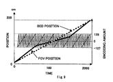
- FIG. 9 illustrates the third embodiment.
- the bed moving velocity is kept constant while the FOV moving velocity is varied area-by-area, and these settings are the same as the second embodiment.
- the phase encoding number is kept constant all over the imaging, for example, scanning from -127 to 128 to obtain one image, and the moving velocity of the FOV in the apparatus coordinate system is controlled to be changed area-by-area.
- the FOV position is moved at a velocity higher than the bed moving velocity.
- the moved distance of the imaging area in the apparatus coordinate system is set to be half of distance in the first and the second measurements, and the velocity of the FOV position in the subject coordinate system is reduced to half.
- controlling of the imaging area movement in the apparatus coordinate system is implemented by controlling, for example, a gradient magnetic field in the slice direction and the frequency of RF pulse, as explained in the description of the first embodiment.
- an area is configured where the FOV position is moved at a velocity lower than a normal status, and according to a range of the area and a ratio how much the velocity is reduced, an imaging time for the whole area is calculated, thereby setting the bed moving velocity.
- the area is configured by designating the area and/or inputting a numeric value, using the scanogram displayed on the display unit.
- performing the imaging firstly, it is performed at a normal moving velocity of the FOV position, that is, at an FOV position moving velocity that is higher than the bed moving velocity.
- the FOV position moving velocity is reduced to a low velocity being configured and the imaging is performed.
- the bed moving velocity and the imaging velocity are not changed.
- the FOV in the apparatus coordinate system is changed.
- the moving velocity of the FOV is reduced as to a part of area, and therefore it is suitable for the imaging in which timing is crucial, for example, imaging the kidney and/or the liver in timely manner, while observing a substance of the kidney and/or liver being dyed by an injected contrast agent.
- the bed moving velocity is set to be identical to an average velocity of the moving velocity of the contrast agent in the bed moving direction (simply referred to as "contrast agent moving velocity"), for example, and the moving velocity of the FOV on the examined subject is controlled according to a difference from the bed moving velocity and the contrast agent moving velocity in the imaging area.
- the bed moving velocity is higher than the FOV moving velocity
- the FOV position is moved to a direction opposite to the bed moving direction.
- the FOV position is moved to a direction being the same as the bed moving direction. Accordingly, the moving velocity of the FOV on the examined subject is made almost the same as the contrast agent moving velocity, whereby it is possible to perform imaging following the contrast agent moving velocity.
- FIG. 10 illustrates the fourth embodiment. Also in the present embodiment, a test object area in which the FOV moving velocity is made different is configured in advance, prior to imaging, and the bed moving velocity is kept constant while the FOV moving velocity is varied area-by-area. These settings are the same as the second and the third embodiments. In the present embodiment, the phase encoding number is kept constant for the entire imaging, and the slice number during one measurement is increased, thereby reducing the moving velocity of the FOV position.
- the FOV position is moved at a velocity higher than the bed moving velocity, and one slice image is obtained by onetime measurement.
- the slice number becomes two within the same TR. Therefore, as illustrated, the slope of the line segment representing the phase encoding (scanning -127 to 128) becomes half of the slope in the case of the first and the second measurements.
- a moved distance of the imaging area in the apparatus coordinate system within one measurement is common in all the measurements.
- the imaging time is extended due to the increase of the slice number.
- the bed moving velocity different from the moving velocity of the FOV position, and by appropriately controlling the FOV position in the apparatus coordinate system, it is possible to suppress the effect of heterogeneity in the static magnetic field to the minimum irrespective of the extension of the imaging time.
- the second, the third, and the fourth embodiments have been explained so far, and those embodiments limit neither the way how to reduce the velocity nor the slice number being explained.
- Time allowance generated by making the bed moving velocity different from the FOV moving velocity is available for various kinds of practical use.
- TR may be extended to be applied to the extended imaging time.
- the present invention is applicable in the similar manner as the fourth embodiment, except that the width of one encoding step (a spacing of fine zigzag line) is enlarged in the third and the second measurements shown in FIG. 10.
- the present embodiment is applied to the case where a part of the examined subject is inclined with respect to the moving direction of the bed.
- the head part 1501 and the body trunk 1502 are subjected to imaging on a cross section (0), which is vertical to the bed.
- the imaging section is set as the imaging section (FOV1) that is inclined only by angle ⁇ 1, following the bending of the femoral region.
- the imaging section is set as the imaging section (FOV2) that is inclined only by the angle ⁇ 2, following the bending of the distal lower extremity.
- the bed moving velocity Vb is set to be an averaged value of v0, v1, and v2, and according to a difference between this bed moving velocity Vb being set and each of the imaging section moving velocities v0, v1, and v2, the imaging is continuously performed while the imaging section is finely adjusted ((b) in the figure).
- the present invention can be applied also in the case where the moving velocity of the imaging section (FOV) in the bed moving direction is varied depending on the oblique of the imaging section.
- the present invention is the most effective in the case where the bed moving velocity is kept constant, and the FOV moved distance varies depending on whether the imaging is ON or OFF, and/or depending on a targeted imaging area.
- the present invention is applicable to a case where the entire imaging area is subjected to imaging at two separate times, that is, the bed is suspended in the course of imaging, or there is a period when the bed moving velocity varies in the course of imaging.
- controlling of the bed movement independently of the aforementioned FOV movement may produce an advantage.
- the present invention is applicable at the velocity on each stage.
- the FOV may be moved, while the bed moving velocity is varied continuously.
- the size of FOV may be kept constant while the entire imaging is performed, or the FOV may be moved while changing the FOV size.
- the FOV size is configured to be large in the body trunk with gaining the moving velocity of the FOV for the examined subject, and the FOV size is configured to be small in the lower extremity with reducing the moving velocity of the FOV for the examined subject.
- the MRI apparatus may display graphs (FIG. 7 to FIG. 10) on an I/O unit (user interface), the graphs showing the bed position and the FOV position plotted on the time axis. Accordingly, the user is allowed to input and check a necessary imaging condition, thereby enhancing operability in executing the present invention.
- a moving velocity of the FOV on a test object is controlled independently of the bed moving velocity, whereby a load onto the examined subject caused by fluctuations of the bed moving velocity is reduced, and it is possible to perform imaging responding to various imaging conditions and requests, which are different by portion in this wide area.
Landscapes
- Health & Medical Sciences (AREA)
- Physics & Mathematics (AREA)
- Life Sciences & Earth Sciences (AREA)
- Engineering & Computer Science (AREA)
- Nuclear Medicine, Radiotherapy & Molecular Imaging (AREA)
- General Health & Medical Sciences (AREA)
- Biophysics (AREA)
- Signal Processing (AREA)
- Physiology (AREA)
- Condensed Matter Physics & Semiconductors (AREA)
- Radiology & Medical Imaging (AREA)
- General Physics & Mathematics (AREA)
- High Energy & Nuclear Physics (AREA)
- Pulmonology (AREA)
- Public Health (AREA)
- Cardiology (AREA)
- Vascular Medicine (AREA)
- Veterinary Medicine (AREA)
- Power Engineering (AREA)
- Pathology (AREA)
- Biomedical Technology (AREA)
- Heart & Thoracic Surgery (AREA)
- Medical Informatics (AREA)
- Molecular Biology (AREA)
- Surgery (AREA)
- Animal Behavior & Ethology (AREA)
- Psychiatry (AREA)
- Computer Vision & Pattern Recognition (AREA)
- Artificial Intelligence (AREA)
- Magnetic Resonance Imaging Apparatus (AREA)
Applications Claiming Priority (2)
| Application Number | Priority Date | Filing Date | Title |
|---|---|---|---|
| JP2004315882 | 2004-10-29 | ||
| PCT/JP2005/019777 WO2006046639A1 (fr) | 2004-10-29 | 2005-10-27 | Dispositif d’imagerie par résonance magnétique nucléaire |
Publications (3)
| Publication Number | Publication Date |
|---|---|
| EP1808127A1 true EP1808127A1 (fr) | 2007-07-18 |
| EP1808127A4 EP1808127A4 (fr) | 2010-07-14 |
| EP1808127B1 EP1808127B1 (fr) | 2015-04-29 |
Family
ID=36227881
Family Applications (1)
| Application Number | Title | Priority Date | Filing Date |
|---|---|---|---|
| EP20050799411 Expired - Lifetime EP1808127B1 (fr) | 2004-10-29 | 2005-10-27 | Imagerie par resonance magnetique a table mobile |
Country Status (5)
| Country | Link |
|---|---|
| US (1) | US7535226B2 (fr) |
| EP (1) | EP1808127B1 (fr) |
| JP (1) | JP4912154B2 (fr) |
| CN (1) | CN100490741C (fr) |
| WO (1) | WO2006046639A1 (fr) |
Cited By (1)
| Publication number | Priority date | Publication date | Assignee | Title |
|---|---|---|---|---|
| DE102009017778A1 (de) * | 2009-04-20 | 2010-11-18 | Siemens Aktiengesellschaft | Verfahren, Magnetresonanzgerät und Computerprogramm für eine Akquisition von Messdaten eines Untersuchungsbereichs eines Untersuchungsobjekts während einer kontinuierlichen Fahrt des Untersuchungsbereichs durch ein Magnetresonanzgerät |
Families Citing this family (23)
| Publication number | Priority date | Publication date | Assignee | Title |
|---|---|---|---|---|
| CN100574701C (zh) * | 2004-09-06 | 2009-12-30 | 株式会社日立医药 | 磁共振成像装置和方法 |
| DE102005023193B4 (de) * | 2005-05-19 | 2015-07-02 | Siemens Aktiengesellschaft | Verfahren zum Abbilden eines Untersuchungsvolumens in einem MR-Spektrometer |
| CN101421637A (zh) * | 2006-04-13 | 2009-04-29 | 皇家飞利浦电子股份有限公司 | 涉及运动补偿的连续移动对象的mri |
| US20100030061A1 (en) * | 2008-07-31 | 2010-02-04 | Canfield Monte R | Navigation system for cardiac therapies using gating |
| DE102008046267B4 (de) * | 2008-09-08 | 2011-04-07 | Siemens Aktiengesellschaft | Bildverzeichnungskorrektur bei kontinuierlicher Tischbewegung |
| DE102008048689A1 (de) * | 2008-09-24 | 2010-04-01 | Siemens Aktiengesellschaft | Verfahren und Signalgewinnungsmodul zur Gewinnung von Trigger-Signalen und Bildakquise- und/oder Bildaufbereitungsverfahren |
| DE102009007361B4 (de) * | 2009-02-04 | 2011-04-07 | Siemens Aktiengesellschaft | Aufnahme von zeitaufgelösten Magnetresonanzdaten |
| JP2010207568A (ja) * | 2009-02-10 | 2010-09-24 | Toshiba Corp | 磁気共鳴イメージング装置 |
| WO2010116782A1 (fr) * | 2009-03-30 | 2010-10-14 | 株式会社 日立製作所 | Dispositif de résonance magnétique |
| JP5502502B2 (ja) * | 2010-01-20 | 2014-05-28 | 株式会社東芝 | 磁気共鳴映像装置 |
| CN102625022B (zh) * | 2011-01-29 | 2014-05-28 | 麦克奥迪实业集团有限公司 | 一种带有像方补偿运动的快速显微切片扫描方法及装置 |
| US10169822B2 (en) | 2011-12-02 | 2019-01-01 | Spireon, Inc. | Insurance rate optimization through driver behavior monitoring |
| US8510200B2 (en) | 2011-12-02 | 2013-08-13 | Spireon, Inc. | Geospatial data based assessment of driver behavior |
| US20140095061A1 (en) * | 2012-10-03 | 2014-04-03 | Richard Franklin HYDE | Safety distance monitoring of adjacent vehicles |
| US8933802B2 (en) | 2012-11-05 | 2015-01-13 | Spireon, Inc. | Switch and actuator coupling in a chassis of a container associated with an intermodal freight transport system |
| US9779379B2 (en) | 2012-11-05 | 2017-10-03 | Spireon, Inc. | Container verification through an electrical receptacle and plug associated with a container and a transport vehicle of an intermodal freight transport system |
| KR101716421B1 (ko) * | 2013-06-21 | 2017-03-14 | 삼성전자주식회사 | 정보 제공 방법 및 정보 제공을 위한 의료 진단 장치 |
| US9779449B2 (en) | 2013-08-30 | 2017-10-03 | Spireon, Inc. | Veracity determination through comparison of a geospatial location of a vehicle with a provided data |
| US20150186991A1 (en) | 2013-12-31 | 2015-07-02 | David M. Meyer | Creditor alert when a vehicle enters an impound lot |
| WO2015138941A1 (fr) * | 2014-03-14 | 2015-09-17 | The General Hospital Corporation | Système et procédé d'empreinte de résonance magnétique |
| US9551788B2 (en) | 2015-03-24 | 2017-01-24 | Jim Epler | Fleet pan to provide measurement and location of a stored transport item while maximizing space in an interior cavity of a trailer |
| CN105559782A (zh) * | 2015-12-22 | 2016-05-11 | 沈阳东软医疗系统有限公司 | 一种患者床移动速度的控制方法、装置及设备 |
| CN110037700B (zh) * | 2019-05-14 | 2023-09-05 | 上海东软医疗科技有限公司 | 一种复合门控信号的获取方法、装置及磁共振设备 |
Family Cites Families (11)
| Publication number | Priority date | Publication date | Assignee | Title |
|---|---|---|---|---|
| JPH034837A (ja) * | 1989-06-01 | 1991-01-10 | Toshiba Corp | 診断用磁気共鳴装置 |
| JP3212753B2 (ja) | 1993-04-30 | 2001-09-25 | ジーイー横河メディカルシステム株式会社 | Mri装置を用いた撮像装置 |
| JPH0871056A (ja) * | 1994-09-05 | 1996-03-19 | Toshiba Corp | 磁気共鳴イメージング装置 |
| JP4127889B2 (ja) * | 1998-03-04 | 2008-07-30 | 株式会社日立メディコ | 磁気共鳴イメージング装置 |
| US6425864B1 (en) * | 1999-04-15 | 2002-07-30 | General Electric Company | Method and apparatus for optimal imaging of the peripheral vasculature |
| US6479996B1 (en) * | 2000-07-10 | 2002-11-12 | Koninklijke Philips Electronics | Magnetic resonance imaging of several volumes |
| JP4515616B2 (ja) * | 2000-09-25 | 2010-08-04 | 株式会社東芝 | 磁気共鳴イメージング装置 |
| US6801034B2 (en) * | 2001-03-30 | 2004-10-05 | General Electric Company | Method and apparatus of acquiring large FOV images without slab-boundary artifacts |
| US6584337B2 (en) * | 2001-11-21 | 2003-06-24 | General Electric Company | Method and system for extended volume imaging using MRI |
| DE10301497B4 (de) * | 2003-01-16 | 2013-12-24 | Siemens Aktiengesellschaft | Magnetresonanz-Projektionsangiographie-Verfahren mit kontinuierlicher Tischverschiebung sowie MRT-Gerät zur Durchführung des Verfahrens |
| JP4112998B2 (ja) * | 2003-01-30 | 2008-07-02 | 株式会社日立メディコ | 磁気共鳴イメージング装置 |
-
2005
- 2005-10-27 JP JP2006543244A patent/JP4912154B2/ja not_active Expired - Fee Related
- 2005-10-27 US US11/666,599 patent/US7535226B2/en not_active Expired - Fee Related
- 2005-10-27 CN CNB2005800371335A patent/CN100490741C/zh not_active Expired - Fee Related
- 2005-10-27 EP EP20050799411 patent/EP1808127B1/fr not_active Expired - Lifetime
- 2005-10-27 WO PCT/JP2005/019777 patent/WO2006046639A1/fr not_active Ceased
Cited By (1)
| Publication number | Priority date | Publication date | Assignee | Title |
|---|---|---|---|---|
| DE102009017778A1 (de) * | 2009-04-20 | 2010-11-18 | Siemens Aktiengesellschaft | Verfahren, Magnetresonanzgerät und Computerprogramm für eine Akquisition von Messdaten eines Untersuchungsbereichs eines Untersuchungsobjekts während einer kontinuierlichen Fahrt des Untersuchungsbereichs durch ein Magnetresonanzgerät |
Also Published As
| Publication number | Publication date |
|---|---|
| EP1808127B1 (fr) | 2015-04-29 |
| CN100490741C (zh) | 2009-05-27 |
| EP1808127A4 (fr) | 2010-07-14 |
| WO2006046639A1 (fr) | 2006-05-04 |
| CN101052348A (zh) | 2007-10-10 |
| US20080111546A1 (en) | 2008-05-15 |
| JPWO2006046639A1 (ja) | 2008-05-22 |
| US7535226B2 (en) | 2009-05-19 |
| JP4912154B2 (ja) | 2012-04-11 |
Similar Documents
| Publication | Publication Date | Title |
|---|---|---|
| EP1808127B1 (fr) | Imagerie par resonance magnetique a table mobile | |
| JP5613811B2 (ja) | 磁気共鳴イメージング装置 | |
| US8842895B2 (en) | Magnetic resonance imaging apparatus and scanning-condition setting method | |
| JP5523718B2 (ja) | 医用撮像装置 | |
| JP6073570B2 (ja) | 磁気共鳴イメージングシステム及び方法 | |
| JP2013223724A (ja) | 検査領域内の磁気共鳴緩和パラメータを高速で空間分解して決定する方法 | |
| US9713449B2 (en) | Magnetic resonance imaging device and magnetic resonance imaging method | |
| JP2001000417A (ja) | マルチ・スラブ及びマルチ・ウィンドウでの心臓の磁気共鳴イメージング法 | |
| JP2002200054A (ja) | Mri装置及びmrイメージング方法 | |
| JP4820567B2 (ja) | 磁気共鳴イメージング装置及び磁気共鳴信号の収集方法 | |
| US20150157277A1 (en) | Magnetic resonance imaging apparatus and magnetic resonance imaging method | |
| US8909321B2 (en) | Diagnostic imaging apparatus, magnetic resonance imaging apparatus, and X-ray CT apparatus | |
| JP4253526B2 (ja) | 磁気共鳴イメージング装置 | |
| US8594767B2 (en) | Magnetic resonance imaging apparatus and magnetic resonance imaging method | |
| JP3434816B2 (ja) | Mri装置 | |
| JP4086544B2 (ja) | 磁気共鳴イメージング装置 | |
| JP4454268B2 (ja) | 磁気共鳴イメージング装置 | |
| JP5371620B2 (ja) | 核磁気共鳴イメージング装置 | |
| US11766188B2 (en) | Magnetic resonance imaging device | |
| US20240329176A1 (en) | Magnetic resonance imaging apparatus and control method of magnetic resonance imaging apparatus | |
| JP4822834B2 (ja) | 磁気共鳴イメージング装置 |
Legal Events
| Date | Code | Title | Description |
|---|---|---|---|
| PUAI | Public reference made under article 153(3) epc to a published international application that has entered the european phase |
Free format text: ORIGINAL CODE: 0009012 |
|
| 17P | Request for examination filed |
Effective date: 20070524 |
|
| AK | Designated contracting states |
Kind code of ref document: A1 Designated state(s): DE FR GB IT NL |
|
| RIN1 | Information on inventor provided before grant (corrected) |
Inventor name: GOTO, TOMOHIRO C/O HITACHI MEDICAL CORPORATION Inventor name: TAKAHASHI, TETSUHIKO |
|
| DAX | Request for extension of the european patent (deleted) | ||
| RBV | Designated contracting states (corrected) |
Designated state(s): DE FR GB IT NL |
|
| RIC1 | Information provided on ipc code assigned before grant |
Ipc: G01R 33/54 20060101ALN20100527BHEP Ipc: A61B 5/055 20060101AFI20061017BHEP Ipc: G01R 33/567 20060101ALN20100527BHEP Ipc: G01R 33/563 20060101ALI20100527BHEP |
|
| A4 | Supplementary search report drawn up and despatched |
Effective date: 20100610 |
|
| 17Q | First examination report despatched |
Effective date: 20120227 |
|
| RIC1 | Information provided on ipc code assigned before grant |
Ipc: A61B 5/055 20060101AFI20131107BHEP Ipc: G01R 33/567 20060101ALN20131107BHEP Ipc: G01R 33/563 20060101ALI20131107BHEP Ipc: G01R 33/54 20060101ALN20131107BHEP Ipc: G01R 33/483 20060101ALN20131107BHEP |
|
| GRAP | Despatch of communication of intention to grant a patent |
Free format text: ORIGINAL CODE: EPIDOSNIGR1 |
|
| RIC1 | Information provided on ipc code assigned before grant |
Ipc: A61B 5/055 20060101AFI20131118BHEP Ipc: G01R 33/567 20060101ALN20131118BHEP Ipc: G01R 33/54 20060101ALN20131118BHEP Ipc: G01R 33/563 20060101ALI20131118BHEP Ipc: G01R 33/483 20060101ALN20131118BHEP |
|
| RIC1 | Information provided on ipc code assigned before grant |
Ipc: G01R 33/563 20060101ALI20131127BHEP Ipc: G01R 33/567 20060101ALN20131127BHEP Ipc: A61B 5/055 20060101AFI20131127BHEP Ipc: G01R 33/483 20060101ALN20131127BHEP Ipc: G01R 33/54 20060101ALN20131127BHEP |
|
| INTG | Intention to grant announced |
Effective date: 20131219 |
|
| GRAS | Grant fee paid |
Free format text: ORIGINAL CODE: EPIDOSNIGR3 |
|
| GRAJ | Information related to disapproval of communication of intention to grant by the applicant or resumption of examination proceedings by the epo deleted |
Free format text: ORIGINAL CODE: EPIDOSDIGR1 |
|
| GRAP | Despatch of communication of intention to grant a patent |
Free format text: ORIGINAL CODE: EPIDOSNIGR1 |
|
| GRAP | Despatch of communication of intention to grant a patent |
Free format text: ORIGINAL CODE: EPIDOSNIGR1 |
|
| GRAJ | Information related to disapproval of communication of intention to grant by the applicant or resumption of examination proceedings by the epo deleted |
Free format text: ORIGINAL CODE: EPIDOSDIGR1 |
|
| INTG | Intention to grant announced |
Effective date: 20140404 |
|
| RIC1 | Information provided on ipc code assigned before grant |
Ipc: G01R 33/563 20060101ALI20140326BHEP Ipc: G01R 33/483 20060101ALN20140326BHEP Ipc: G01R 33/567 20060101ALN20140326BHEP Ipc: A61B 5/055 20060101AFI20140326BHEP Ipc: G01R 33/54 20060101ALN20140326BHEP |
|
| GRAP | Despatch of communication of intention to grant a patent |
Free format text: ORIGINAL CODE: EPIDOSNIGR1 |
|
| INTC | Intention to grant announced (deleted) | ||
| INTG | Intention to grant announced |
Effective date: 20140414 |
|
| INTG | Intention to grant announced |
Effective date: 20140506 |
|
| GRAJ | Information related to disapproval of communication of intention to grant by the applicant or resumption of examination proceedings by the epo deleted |
Free format text: ORIGINAL CODE: EPIDOSDIGR1 |
|
| GRAP | Despatch of communication of intention to grant a patent |
Free format text: ORIGINAL CODE: EPIDOSNIGR1 |
|
| GRAC | Information related to communication of intention to grant a patent modified |
Free format text: ORIGINAL CODE: EPIDOSCIGR1 |
|
| INTG | Intention to grant announced |
Effective date: 20140506 |
|
| INTG | Intention to grant announced |
Effective date: 20141113 |
|
| GRAS | Grant fee paid |
Free format text: ORIGINAL CODE: EPIDOSNIGR3 |
|
| GRAA | (expected) grant |
Free format text: ORIGINAL CODE: 0009210 |
|
| AK | Designated contracting states |
Kind code of ref document: B1 Designated state(s): DE FR GB IT NL |
|
| REG | Reference to a national code |
Ref country code: GB Ref legal event code: FG4D |
|
| REG | Reference to a national code |
Ref country code: DE Ref legal event code: R096 Ref document number: 602005046454 Country of ref document: DE Effective date: 20150611 |
|
| REG | Reference to a national code |
Ref country code: NL Ref legal event code: T3 |
|
| PGFP | Annual fee paid to national office [announced via postgrant information from national office to epo] |
Ref country code: DE Payment date: 20151030 Year of fee payment: 11 |
|
| REG | Reference to a national code |
Ref country code: DE Ref legal event code: R097 Ref document number: 602005046454 Country of ref document: DE |
|
| PGFP | Annual fee paid to national office [announced via postgrant information from national office to epo] |
Ref country code: NL Payment date: 20151007 Year of fee payment: 11 |
|
| PLBE | No opposition filed within time limit |
Free format text: ORIGINAL CODE: 0009261 |
|
| STAA | Information on the status of an ep patent application or granted ep patent |
Free format text: STATUS: NO OPPOSITION FILED WITHIN TIME LIMIT |
|
| 26N | No opposition filed |
Effective date: 20160201 |
|
| PG25 | Lapsed in a contracting state [announced via postgrant information from national office to epo] |
Ref country code: IT Free format text: LAPSE BECAUSE OF FAILURE TO SUBMIT A TRANSLATION OF THE DESCRIPTION OR TO PAY THE FEE WITHIN THE PRESCRIBED TIME-LIMIT Effective date: 20150429 |
|
| GBPC | Gb: european patent ceased through non-payment of renewal fee |
Effective date: 20151027 |
|
| PG25 | Lapsed in a contracting state [announced via postgrant information from national office to epo] |
Ref country code: GB Free format text: LAPSE BECAUSE OF NON-PAYMENT OF DUE FEES Effective date: 20151027 |
|
| REG | Reference to a national code |
Ref country code: FR Ref legal event code: ST Effective date: 20160630 |
|
| PG25 | Lapsed in a contracting state [announced via postgrant information from national office to epo] |
Ref country code: FR Free format text: LAPSE BECAUSE OF NON-PAYMENT OF DUE FEES Effective date: 20151102 |
|
| REG | Reference to a national code |
Ref country code: DE Ref legal event code: R119 Ref document number: 602005046454 Country of ref document: DE |
|
| REG | Reference to a national code |
Ref country code: NL Ref legal event code: MM Effective date: 20161101 |
|
| PG25 | Lapsed in a contracting state [announced via postgrant information from national office to epo] |
Ref country code: DE Free format text: LAPSE BECAUSE OF NON-PAYMENT OF DUE FEES Effective date: 20170503 |
|
| PG25 | Lapsed in a contracting state [announced via postgrant information from national office to epo] |
Ref country code: NL Free format text: LAPSE BECAUSE OF NON-PAYMENT OF DUE FEES Effective date: 20161101 |