EP1808340A1 - Capteur d'impulsion - Google Patents
Capteur d'impulsion Download PDFInfo
- Publication number
- EP1808340A1 EP1808340A1 EP07100605A EP07100605A EP1808340A1 EP 1808340 A1 EP1808340 A1 EP 1808340A1 EP 07100605 A EP07100605 A EP 07100605A EP 07100605 A EP07100605 A EP 07100605A EP 1808340 A1 EP1808340 A1 EP 1808340A1
- Authority
- EP
- European Patent Office
- Prior art keywords
- cable
- elastic structure
- impulse
- insertion hole
- front bumper
- Prior art date
- Legal status (The legal status is an assumption and is not a legal conclusion. Google has not performed a legal analysis and makes no representation as to the accuracy of the status listed.)
- Granted
Links
- 238000003780 insertion Methods 0.000 claims abstract description 44
- 230000037431 insertion Effects 0.000 claims abstract description 44
- 239000000463 material Substances 0.000 claims abstract description 16
- 239000013307 optical fiber Substances 0.000 claims description 60
- 229920003002 synthetic resin Polymers 0.000 claims description 41
- 239000000057 synthetic resin Substances 0.000 claims description 41
- 239000000835 fiber Substances 0.000 description 12
- 230000003287 optical effect Effects 0.000 description 12
- 239000011162 core material Substances 0.000 description 8
- 230000005540 biological transmission Effects 0.000 description 7
- 230000035945 sensitivity Effects 0.000 description 7
- 238000005253 cladding Methods 0.000 description 6
- 239000011295 pitch Substances 0.000 description 4
- 229920005989 resin Polymers 0.000 description 4
- 239000011347 resin Substances 0.000 description 4
- -1 acryl Chemical group 0.000 description 3
- 230000007423 decrease Effects 0.000 description 3
- 238000010586 diagram Methods 0.000 description 3
- 229910001369 Brass Inorganic materials 0.000 description 2
- 239000010951 brass Substances 0.000 description 2
- 229920003051 synthetic elastomer Polymers 0.000 description 2
- 239000005061 synthetic rubber Substances 0.000 description 2
- 229920000181 Ethylene propylene rubber Polymers 0.000 description 1
- 244000043261 Hevea brasiliensis Species 0.000 description 1
- VYPSYNLAJGMNEJ-UHFFFAOYSA-N Silicium dioxide Chemical compound O=[Si]=O VYPSYNLAJGMNEJ-UHFFFAOYSA-N 0.000 description 1
- XUIMIQQOPSSXEZ-UHFFFAOYSA-N Silicon Chemical compound [Si] XUIMIQQOPSSXEZ-UHFFFAOYSA-N 0.000 description 1
- 230000001133 acceleration Effects 0.000 description 1
- 230000006835 compression Effects 0.000 description 1
- 238000007906 compression Methods 0.000 description 1
- 238000010276 construction Methods 0.000 description 1
- 230000003111 delayed effect Effects 0.000 description 1
- 229920001971 elastomer Polymers 0.000 description 1
- 230000036540 impulse transmission Effects 0.000 description 1
- 238000012986 modification Methods 0.000 description 1
- 230000004048 modification Effects 0.000 description 1
- 229920003052 natural elastomer Polymers 0.000 description 1
- 229920001194 natural rubber Polymers 0.000 description 1
- 239000004033 plastic Substances 0.000 description 1
- 239000005060 rubber Substances 0.000 description 1
- 229910052710 silicon Inorganic materials 0.000 description 1
- 239000010703 silicon Substances 0.000 description 1
- 229920002379 silicone rubber Polymers 0.000 description 1
- 229910001220 stainless steel Inorganic materials 0.000 description 1
- 239000010935 stainless steel Substances 0.000 description 1
- 229920001187 thermosetting polymer Polymers 0.000 description 1
- XLYOFNOQVPJJNP-UHFFFAOYSA-N water Substances O XLYOFNOQVPJJNP-UHFFFAOYSA-N 0.000 description 1
Images

Classifications
-
- B—PERFORMING OPERATIONS; TRANSPORTING
- B60—VEHICLES IN GENERAL
- B60R—VEHICLES, VEHICLE FITTINGS, OR VEHICLE PARTS, NOT OTHERWISE PROVIDED FOR
- B60R21/00—Arrangements or fittings on vehicles for protecting or preventing injuries to occupants or pedestrians in case of accidents or other traffic risks
- B60R21/01—Electrical circuits for triggering passive safety arrangements, e.g. airbags, safety belt tighteners, in case of vehicle accidents or impending vehicle accidents
- B60R21/013—Electrical circuits for triggering passive safety arrangements, e.g. airbags, safety belt tighteners, in case of vehicle accidents or impending vehicle accidents including means for detecting collisions, impending collisions or roll-over
- B60R21/0136—Electrical circuits for triggering passive safety arrangements, e.g. airbags, safety belt tighteners, in case of vehicle accidents or impending vehicle accidents including means for detecting collisions, impending collisions or roll-over responsive to actual contact with an obstacle, e.g. to vehicle deformation, bumper displacement or bumper velocity relative to the vehicle
-
- G—PHYSICS
- G01—MEASURING; TESTING
- G01L—MEASURING FORCE, STRESS, TORQUE, WORK, MECHANICAL POWER, MECHANICAL EFFICIENCY, OR FLUID PRESSURE
- G01L1/00—Measuring force or stress, in general
- G01L1/24—Measuring force or stress, in general by measuring variations of optical properties of material when it is stressed, e.g. by photoelastic stress analysis using infrared, visible light, ultraviolet
- G01L1/242—Measuring force or stress, in general by measuring variations of optical properties of material when it is stressed, e.g. by photoelastic stress analysis using infrared, visible light, ultraviolet the material being an optical fibre
- G01L1/243—Measuring force or stress, in general by measuring variations of optical properties of material when it is stressed, e.g. by photoelastic stress analysis using infrared, visible light, ultraviolet the material being an optical fibre using means for applying force perpendicular to the fibre axis
-
- B—PERFORMING OPERATIONS; TRANSPORTING
- B60—VEHICLES IN GENERAL
- B60R—VEHICLES, VEHICLE FITTINGS, OR VEHICLE PARTS, NOT OTHERWISE PROVIDED FOR
- B60R21/00—Arrangements or fittings on vehicles for protecting or preventing injuries to occupants or pedestrians in case of accidents or other traffic risks
- B60R21/01—Electrical circuits for triggering passive safety arrangements, e.g. airbags, safety belt tighteners, in case of vehicle accidents or impending vehicle accidents
- B60R2021/0104—Communication circuits for data transmission
- B60R2021/01081—Transmission medium
- B60R2021/01095—Transmission medium optical
Definitions
- This invention relates to an impulse sensor for sensing an impulse.
- an impulse sensor using a cable As a conventional impulse sensor, there is an impulse sensor using a cable. This impulse sensor is characterized in that an impulse can be sensed in an entire longitudinal direction of the cable.
- cable sensors of a type using an optical fiber in which propagation light is varied by deformation of the optical fiber of a type using a cable in which electric potential is varied by pressure, of a type using pressure-sensitive rubber in which electric resistance is varied by pressure, and of a type using longitudinally arranged switches which are turned ON/OFF by an impulse.
- the impulse sensor using an optical fiber is caused to sense an impulse by applying, to an optical fiber made of quartz glass or synthetic resin, an impulse, such as pressure, acceleration or strain, causing bend loss and compression loss of the optical fiber, and thereby varying propagation light quantity in the optical fiber (See JP-A-9-26370 and JP-A-2002-531812 , for example).
- an object of this invention to provide an impulse sensor, which has advantages over known sensors, and which in particular can correct detected value differences in portions of the vehicle.
- an impulse sensor comprises:
- an impulse sensor comprises:
- an impulse sensor comprises:
- the cable comprises a synthetic resin optical fiber.
- an impulse sensor comprises:
- an impulse sensor comprises:
- the distance from the central line of the cable to the outer surface of the elastic structure is shorter at the middle portion of the front bumper than that at the end portion of the front bumper in the longitudinal direction of the front bumper.
- the inside diameter of the cable insertion hole is smaller at the middle portion of the front bumper than that at the end portion of the front bumper in the longitudinal direction of the front bumper.
- the outside diameter of the cable is greater at the middle portion of the front bumper than that at the end portion of the front bumper in the longitudinal direction of the front bumper.
- the invention provides the advantage that the impulse sensor is able to vary its sensitivity in the longitudinal direction to correct a detected value.
- An impulse sensor 1 shown in FIGS.1 and 2 comprises an elongate elastic structure 2 formed of a material to be deformed according to an impulse, an optical fiber insertion hole 3 cut in the elastic structure 2, a synthetic resin optical fiber 4 inserted through the hole 3 detect a variation in propagation light quantity due to its deformation, and a rigid sheet member 5 disposed along the hole 3 in the elastic structure 2.
- the sheet member 5 has protrusions arranged at specified pitches.
- the protrusions of the sheet member 5 may be formed by vertically cutting through-holes at appropriate longitudinal pitches therein so that protruding portions 6 are left as edges of the through-holes.
- the protrusions of the sheet member 5 may be formed by longitudinally providing protruding portions 7 at appropriate pitches.
- the sheet member 5 is formed in a thin long sheet shape using a rigid material such as hard plastic, brass (BS), stainless steel (SUS), etc.
- the synthetic resin optical fiber 4 comprises a high refractive index fiber core and low refractive index fiber cladding provided around the fiber core, and is suitable for this impulse sensor.
- the fiber core is formed of a core material such as a cross-linked acryl resin (thermosetting acryl resin), a silicon resin, etc. and the fiber cladding is formed of a cladding material such as a moisture-impermeable fluororesin, etc.
- a core material such as a cross-linked acryl resin (thermosetting acryl resin), a silicon resin, etc.
- the fiber cladding is formed of a cladding material such as a moisture-impermeable fluororesin, etc.
- the outside diameter of the fiber core is ⁇ 1.5 mm
- the outside diameter of the fiber cladding is ⁇ 2.2 mm
- the fiber core is formed of a cross-linked acryl resin.
- the Young modulus of the fiber core is 3 GPa at 20°C.
- the elastic structure 2 is formed in a thin elongate stick shape, and is longitudinally provided with the optical fiber insertion hole 3 whose diameter is larger than a fiber cladding diameter of the synthetic resin optical fiber 4, and the sheet member 5 is buried along the hole 3 in the elastic structure 2.
- the synthetic resin optical fiber 4 is inserted through the hole 3, and after the insertion of the synthetic resin optical fiber 4, to prevent water or the like from entering the hole 3, both longitudinal ends (not shown) of the hole 3 are sealed.
- the material of the elastic structure 2 uses natural rubber, synthetic rubber, or the like, for example.
- synthetic rubber there are silicon rubber, ethylene-propylene rubber, etc.
- the optical fiber impulse sensor 1 has the structure in which the synthetic resin optical fiber 4 with outside diameter ⁇ 2.2 mm is inserted through the hole 3 cut in the elastic structure 2 .
- a light-emitting diode (not shown), for example, which emits constant wavelength light as a light source. Light emitted is injected into the synthetic resin optical fiber 4.
- a photodiode (not shown), for example, as a light-receiving element. Light quantity transmitted through the synthetic resin optical fiber 4 is sensed by the photodiode, and a variation in the light quantity is detected, thereby allowing an impulse applied to the impulse sensor 1 to be sensed.
- the light-emitting diode typically operates at a wavelength of 660 nm.
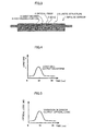
- FIG. 2A shows a state of the impulse sensor 1 before receiving an impulse.
- the state of receiving no impulse there is no deformation of the elastic structure 2, and the synthetic resin optical fiber 4 does not receive any stress, and therefore has few strains caused.
- FIG.3 shows a state of the impulse sensor 1 when receiving an impulse.
- the impulse applied to the impulse sensor 1 is a pressing force applied in the diametrical direction of the synthetic resin optical fiber 4, which causes the lower portion of the synthetic resin optical fiber 4 to abut the protruding portions 6 at predetermined longitudinal pitches, and which therefore causes the protruding portions 6 to deform the synthetic resin optical fiber 4 at the areas respectively abutting the protruding portion 6.
- the amount of deformation is based on the load.
- the synthetic resin optical fiber 4 becomes strained and bent at the protruding portions 6, therefore leading to a large transmission loss (optical loss).
- the synthetic resin optical fiber 4 when the impulse sensor 1 receives an impulse the synthetic resin optical fiber 4 is effectively concentratedly stressed at the portions respectively abutting the protruding portions 6, and strain caused in the fiber core and fiber cladding forming the synthetic resin optical fiber 4 causes an increase in transmission loss (optical loss) of the synthetic resin optical fiber 4.
- the increase of this transmission loss causes a decrease in light quantity passing through the synthetic resin optical fiber 4. Because the increase of this transmission loss is related to the magnitude of the load applied to the impulse sensor 1, by measuring variation with time of the transmission loss, the magnitude of the impulse, the length of time of receiving the impulse, etc. can be sensed.
- FIG.4 shows a variation with time of load sensed by a conventional impulse sensor load cell.
- the horizontal axis represents time (unit: ms)
- the vertical axis represents load (unit: kN) received by the load cell.
- FIG.5 shows a variation in optical loss of the synthetic resin optical fiber 4 when the same impulse as in the load cell is applied to the impulse sensor 1 of FIG. 1.
- the horizontal axis represents time (unit: ms), and the vertical axis represents optical loss (unit: dB) of the impulse sensor 1.
- the optical loss of the impulse sensor 1 when no impulse is applied, the optical loss of the impulse sensor 1 is small, whereas when an impulse is applied, the optical loss of the impulse sensor 1 increases to the maximum optical loss in approximately 10 ms, and subsequently decreases to the original state before receiving the impulse.
- the impulse sensor 1 of FIG.1 is as effective in impulse sensing as the conventional impulse sensor (load cell). That is, the variation with time of the optical loss of the impulse sensor 1 has the pattern similar to the output varying with time of the load cell, and the degree of the optical loss of the impulse sensor 1 corresponds to the degree of the impulse received by the object to be measured.
- the impulse sensor 1 senses an impulse received by an optical loss variation through the synthetic resin optical fiber 4, it can sense the impulse without being affected by electromagnetic noise caused or received in the impulse sensor 1 -installed location.
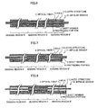
- an impulse sensor 61 differs from the impulse sensor 1 described in relation to FIG. 1.
- the inside diameter of the optical fiber insertion hole 3 is the same in every longitudinal portion, and the inside diameter of the synthetic resin optical fiber 4 is the same in every longitudinal portion, so that, under the condition of the constant inside diameter of the optical fiber insertion hole 3, the elastic structure 2 is thick in the right and left end portions and thin in the middle portion, as shown.
- the impulse sensor 61 is longitudinally divided into 3 sensing regions: sensing regions B and B' in the left and right end portions respectively, and sensing region C in the middle portion, as shown.
- the thickness of the elastic structure 2 in the sensing regions B and B' is 6 mm
- the thickness of the elastic structure 2 in the sensing region C is 4.5 mm.
- an impulse sensor 71 differs from the impulse sensor 1 described in relation to FIG. 1.
- the inside diameter of the optical fiber insertion hole 3 is not constant along longitudinal portions of the elastic structure 2.
- the inside diameter of the optical fiber insertion hole 3 is thicker in the right and left end portions and thinner in the middle portion, as shown.
- the outside diameter of the synthetic resin optical fiber 4 is the same in every longitudinal portion.
- the impulse sensor 71 is longitudinally divided into 3 sensing regions: sensing regions B and B' in the left and right end portions respectively, and sensing region C in the middle portion, as shown.
- sensing regions B and B' in the left and right end portions respectively
- sensing region C in the middle portion, as shown.
- the inside diameter of the optical fiber insertion hole 3 in the sensing regions B and B' is 3.0 mm
- the inside diameter of the optical fiber insertion hole 3 in the sensing region C is 2.3 mm.
- an impulse sensor 81 differs from the impulse sensor 1 described in relation to FIG. 1.
- the outside diameter of the synthetic resin optical fiber 4 is not constant along longitudinal portions of the elastic structure 2.
- the outside diameter of the synthetic resin optical fiber 4 is thinner in the right and left end portions and thicker in the middle portion, as shown.
- the inside diameter of the optical fiber insertion hole 3 is the same in every longitudinal portion.
- the impulse sensor 81 is longitudinally divided into 3 sensing regions: sensing regions B and B' in the left and right end portions respectively, and sensing region C in the middle portion, as shown.
- the outside diameter of the synthetic resin optical fiber 4 in the sensing regions B and B' is 1.8 mm
- the outside diameter of the synthetic resin optical fiber 4 in the sensing region C is 2.2 mm.
- the impulse sensor 71 of FIG. 7 since a gap is present between the synthetic resin optical fiber 4 and the elastic structure 2 in the sensing regions B and B', after load is applied to the outer surface of the elastic structure 2, it takes time for the gap to be compressed, and the time at which the load is applied to the synthetic resin optical fiber 4 is therefore delayed, in comparison to the sensing region C. Because of this time delay, the sensing regions B and B' are lower in the sensitivity of the impulse sensor to impulses than the sensing region C.
- the sensing regions B and B' are lower in the sensitivity of the impulse sensor to impulses than the sensing region C.
- FIGS.6-8 vary only any one of the distance from the central line of the synthetic resin optical fiber 4 to outer surface of the elastic structure 2, the diameter of the optical fiber insertion hole 3, or the diameter of the synthetic resin optical fiber 4 according to longitudinal portions of the elastic structure 2, any two or more of these may be varied according to longitudinal portions of the elastic structure.
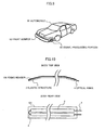
- an automobile 91 is provided with a front bumper 92 that extends from its body front to sides.
- An impulse sensor according to this invention is installed along this front bumper 92 of the vehicle.
- the sensor comprises a long elastic structure formed of a material to be deformed according to an impulse, a cable insertion hole cut in the elastic structure, and a cable inserted through the hole to cause a variation in propagation energy due to its deformation, and varies any one or more of the distance from the central line of the cable to outer surface of the elastic structure, the distance from the central line of the cable to inner surface of the cable insertion hole (i.e., inside diameter of the cable insertion hole), and the distance from the central line of the cable to outer surface of the cable (i.e., outside diameter of the cable), in the middle portion and in the left and right end portions of the front bumper 92.
- the rigidity of the front bumper 92 is small in the middle portion and large in the left and right end portions, and that the sensitivity thereof is higher in the left and right end portions than in the middle portion.
- the impulse sensors of the embodiments of FIGS.6-8 are then installed such that the sensing regions B and B' are arranged in the left and right end portions of the front bumper and that the sensing region C is in the middle portion.
- a signal processing portion 93 containing a light source and a light receiving element, may be provided in any place within the automobile 91.
- the high-sensitivity sensing region C is laid in the middle portion of the small-rigidity and low-sensitivity bumper, and the low-sensitivity sensing regions B and B' in the left and right end portions of the large-rigidity and high-sensitivity bumper, thus allowing the impulse sensor to output the same output value for the same collision load.
- the low-sensitivity sensing region may be laid in the middle portion of the bumper, and the high-sensitivity sensing regions in the left and right end portions of the bumper.
- an elastic structure 2 is fixed to a thin sheet fixing member 101 formed along the bend shape of the bumper, and the fixing member 101 is fixed to the inner side (back side) of the bumper.
- the upper surface of the elastic structure 2 shown in FIGS.6-8 is in contact with the fixing member 101.
- the elastic structure 2 is folded and drawn around. Specifically, in the upper half of the fixing member 101, the elastic structure 2 is substantially straightened from the right to left end shown, and is folded with the bare synthetic resin optical fiber 4 at the left end shown, and is substantially straightened from the left to right end shown.
- the sensing regions B and B' and the sensing region C explained in FIGS.6-8 are formed in one direction and then in the opposite direction. The drawing of the synthetic resin optical fiber 4 to a light source and a light receiving element (both not shown) can be achieved.
Landscapes
- Engineering & Computer Science (AREA)
- Mechanical Engineering (AREA)
- Physics & Mathematics (AREA)
- General Physics & Mathematics (AREA)
- Force Measurement Appropriate To Specific Purposes (AREA)
- Length Measuring Devices By Optical Means (AREA)
Applications Claiming Priority (1)
| Application Number | Priority Date | Filing Date | Title |
|---|---|---|---|
| JP2006008688A JP4891620B2 (ja) | 2006-01-17 | 2006-01-17 | 衝撃検知センサ |
Publications (2)
| Publication Number | Publication Date |
|---|---|
| EP1808340A1 true EP1808340A1 (fr) | 2007-07-18 |
| EP1808340B1 EP1808340B1 (fr) | 2012-05-16 |
Family
ID=37988976
Family Applications (1)
| Application Number | Title | Priority Date | Filing Date |
|---|---|---|---|
| EP07100605A Not-in-force EP1808340B1 (fr) | 2006-01-17 | 2007-01-16 | Capteur d'impulsion |
Country Status (3)
| Country | Link |
|---|---|
| US (1) | US7520157B2 (fr) |
| EP (1) | EP1808340B1 (fr) |
| JP (1) | JP4891620B2 (fr) |
Cited By (2)
| Publication number | Priority date | Publication date | Assignee | Title |
|---|---|---|---|---|
| WO2008101934A1 (fr) * | 2007-02-21 | 2008-08-28 | Continental Automotive Gmbh | Détecteur de collision pour un véhicule automobile |
| US10286936B2 (en) | 2014-03-12 | 2019-05-14 | Siemens Ag Österreich | Device for detecting obstacles for rail vehicles |
Families Citing this family (4)
| Publication number | Priority date | Publication date | Assignee | Title |
|---|---|---|---|---|
| KR100959652B1 (ko) * | 2007-08-13 | 2010-05-26 | 김도형 | 고무자석 이용 진동충격센서 |
| WO2015096909A1 (fr) * | 2013-12-23 | 2015-07-02 | Bombardier Transportation Gmbh | Dispositif de détection d'urgence pour un véhicule ferroviaire et mécanisme de roulement associé, véhicule ferroviaire et procédé de détection d'urgence |
| JP6146383B2 (ja) * | 2014-08-08 | 2017-06-14 | トヨタ自動車株式会社 | 圧力チューブ式歩行者衝突検知センサを備えた車両用バンパ構造 |
| JP7552005B2 (ja) * | 2019-08-07 | 2024-09-18 | 三菱自動車工業株式会社 | 車体構造 |
Citations (7)
| Publication number | Priority date | Publication date | Assignee | Title |
|---|---|---|---|---|
| JPH05116592A (ja) * | 1991-10-30 | 1993-05-14 | Ishikawajima Harima Heavy Ind Co Ltd | 車体衝突検出装置 |
| DE4407763A1 (de) * | 1994-03-09 | 1995-09-14 | Bosch Gmbh Robert | Sensor |
| US20030164755A1 (en) * | 2000-05-13 | 2003-09-04 | Rainer Moritz | Vehicle intrusion detector for detecting the severity of an accident |
| DE10340243A1 (de) | 2002-09-25 | 2004-04-01 | Acts Advanced Car Technology Systems Gmbh & Co.Kg | Sensoreinrichtung und Verfahren zur Erfassung einer äußeren Stoßbelastung an einem Fahrzeug |
| EP1442943A2 (fr) * | 2002-12-05 | 2004-08-04 | Siemens Restraint Systems GmbH | Système de protection pour piétons et méthode de déclenchement d'un tel système selon l'impact |
| US20050121925A1 (en) * | 2003-11-26 | 2005-06-09 | Iee International Electronics & Engineering S.A. | Collision sensor for vehicle bumper |
| EP1726491A2 (fr) * | 2005-04-04 | 2006-11-29 | Denso Corporation | Dispositif de détection de collision pour véhicule |
Family Cites Families (16)
| Publication number | Priority date | Publication date | Assignee | Title |
|---|---|---|---|---|
| SE443656B (sv) * | 1984-07-20 | 1986-03-03 | Ericsson Telefon Ab L M | Mikrobojkenslig optisk fiberkabel |
| US4594485A (en) * | 1985-04-04 | 1986-06-10 | Brown Jr Milton F | Impact sensor |
| JPS623688A (ja) * | 1985-06-28 | 1987-01-09 | Honda Motor Co Ltd | 物体検知装置 |
| CH666552A5 (fr) * | 1986-03-06 | 1988-07-29 | Suisse Electronique Microtech | Capteur a fibre optique a microcourbures. |
| US5392024A (en) * | 1991-06-14 | 1995-02-21 | Toyota Jidosha Kabushiki Kaisha | Collision detection system |
| JPH0926370A (ja) | 1995-07-13 | 1997-01-28 | Nissei Denki Kk | 加圧センサ |
| CA2254538C (fr) | 1998-11-26 | 2006-02-07 | Canpolar East Inc. | Detecteur de deformations causees par les collisions utilise dans la zone d'absorption de choc d'un vehicule |
| JP2002267549A (ja) * | 2001-03-14 | 2002-09-18 | Sumitomo Electric Ind Ltd | 光ファイバ衝突検知センサおよびその形成方法 |
| JP3632080B2 (ja) * | 2001-11-22 | 2005-03-23 | 独立行政法人産業技術総合研究所 | プローブ型光ファイバセンサ |
| CA2424708A1 (fr) * | 2003-04-08 | 2004-10-08 | Lee A. Danisch | Methode et appareil pour detecter un impact entre un vehicule et un objet |
| JP4360172B2 (ja) * | 2003-10-09 | 2009-11-11 | ヤマハ株式会社 | 光ファイバ保持部材 |
| JP4148473B2 (ja) * | 2003-10-29 | 2008-09-10 | 株式会社デンソー | 車両用衝突物体判別装置 |
| JP4287765B2 (ja) * | 2004-02-26 | 2009-07-01 | 日立電線株式会社 | 衝撃検知光ファイバセンサ及びそれを用いたシステム |
| DE102004017270B3 (de) * | 2004-04-07 | 2005-12-01 | Siemens Ag | Vorrichtung zum Erkennen eines Aufpralls auf ein Fahrzeug |
| JP2006111053A (ja) * | 2004-10-12 | 2006-04-27 | Denso Corp | 車両用ワイヤ式衝突検出装置 |
| JP4881011B2 (ja) * | 2006-01-16 | 2012-02-22 | 日立電線株式会社 | 衝撃検知光ファイバセンサの製造方法 |
-
2006
- 2006-01-17 JP JP2006008688A patent/JP4891620B2/ja not_active Expired - Fee Related
-
2007
- 2007-01-03 US US11/649,118 patent/US7520157B2/en not_active Expired - Fee Related
- 2007-01-16 EP EP07100605A patent/EP1808340B1/fr not_active Not-in-force
Patent Citations (7)
| Publication number | Priority date | Publication date | Assignee | Title |
|---|---|---|---|---|
| JPH05116592A (ja) * | 1991-10-30 | 1993-05-14 | Ishikawajima Harima Heavy Ind Co Ltd | 車体衝突検出装置 |
| DE4407763A1 (de) * | 1994-03-09 | 1995-09-14 | Bosch Gmbh Robert | Sensor |
| US20030164755A1 (en) * | 2000-05-13 | 2003-09-04 | Rainer Moritz | Vehicle intrusion detector for detecting the severity of an accident |
| DE10340243A1 (de) | 2002-09-25 | 2004-04-01 | Acts Advanced Car Technology Systems Gmbh & Co.Kg | Sensoreinrichtung und Verfahren zur Erfassung einer äußeren Stoßbelastung an einem Fahrzeug |
| EP1442943A2 (fr) * | 2002-12-05 | 2004-08-04 | Siemens Restraint Systems GmbH | Système de protection pour piétons et méthode de déclenchement d'un tel système selon l'impact |
| US20050121925A1 (en) * | 2003-11-26 | 2005-06-09 | Iee International Electronics & Engineering S.A. | Collision sensor for vehicle bumper |
| EP1726491A2 (fr) * | 2005-04-04 | 2006-11-29 | Denso Corporation | Dispositif de détection de collision pour véhicule |
Cited By (3)
| Publication number | Priority date | Publication date | Assignee | Title |
|---|---|---|---|---|
| WO2008101934A1 (fr) * | 2007-02-21 | 2008-08-28 | Continental Automotive Gmbh | Détecteur de collision pour un véhicule automobile |
| US10286936B2 (en) | 2014-03-12 | 2019-05-14 | Siemens Ag Österreich | Device for detecting obstacles for rail vehicles |
| EP3116762B1 (fr) * | 2014-03-12 | 2024-04-17 | Siemens Mobility Austria GmbH | Dispositif de detection d'obstacles pour véhicules ferroviaires |
Also Published As
| Publication number | Publication date |
|---|---|
| US7520157B2 (en) | 2009-04-21 |
| US20070180891A1 (en) | 2007-08-09 |
| EP1808340B1 (fr) | 2012-05-16 |
| JP4891620B2 (ja) | 2012-03-07 |
| JP2007192566A (ja) | 2007-08-02 |
Similar Documents
| Publication | Publication Date | Title |
|---|---|---|
| EP1808340A1 (fr) | Capteur d'impulsion | |
| CA2839212C (fr) | Cable de fibre optique avec une meilleure sensibilite directionnelle | |
| EP1907809B1 (fr) | Manometre foliaire | |
| US6429421B1 (en) | Flexible fiber optic microbend device, with interlocking flexible fibers, sensors, and method use | |
| US20150355015A1 (en) | Fibre Optic Cable for Acoustic/Seismic Sensing | |
| JP4287765B2 (ja) | 衝撃検知光ファイバセンサ及びそれを用いたシステム | |
| JP2004156945A (ja) | 車両衝突検出装置 | |
| EP1749704B1 (fr) | Capteur à fibre optique, procédé de fabrication correspondant et dispositif de détection de collision | |
| JP5433826B2 (ja) | 重量計測素子及び重量計 | |
| US7747386B2 (en) | Collision detection sensor | |
| EP1795878A1 (fr) | Capteur à fibre optique de détection de chocs | |
| WO2016186054A1 (fr) | Capteur de contrainte et gabarit de fixation d'un capteur de contrainte | |
| JP4268528B2 (ja) | 衝撃検知光ファイバセンサ及びそれを用いたシステム | |
| JP4791782B2 (ja) | 衝撃検知光ファイバセンサ | |
| US12181331B2 (en) | Transducer assembly for mounting in a roadway | |
| EP1785707A2 (fr) | Capteur d'impulsion à fibre optique | |
| KR100414857B1 (ko) | 광섬유를 이용한 이동체 감지용 압력 센서 | |
| JP4728705B2 (ja) | 衝撃検知光ファイバセンサ並びに荷重集中板 | |
| JP4783097B2 (ja) | 衝撃検知光ファイバセンサ | |
| JP4730322B2 (ja) | 車両用バンパ構造 | |
| JP2007155588A (ja) | 衝撃検知光ファイバセンサ | |
| JP2005140752A (ja) | 衝撃センサ | |
| JP4783160B2 (ja) | 衝撃検知光ファイバセンサ及びその製造方法 | |
| JP2006250562A (ja) | 衝撃検知光ファイバセンサ及びその製造方法 | |
| EP1707447A1 (fr) | Capteur optique de tension de ceinture de sécurité |
Legal Events
| Date | Code | Title | Description |
|---|---|---|---|
| PUAI | Public reference made under article 153(3) epc to a published international application that has entered the european phase |
Free format text: ORIGINAL CODE: 0009012 |
|
| AK | Designated contracting states |
Kind code of ref document: A1 Designated state(s): AT BE BG CH CY CZ DE DK EE ES FI FR GB GR HU IE IS IT LI LT LU LV MC NL PL PT RO SE SI SK TR |
|
| AX | Request for extension of the european patent |
Extension state: AL BA HR MK YU |
|
| 17P | Request for examination filed |
Effective date: 20071106 |
|
| AKX | Designation fees paid |
Designated state(s): DE FR GB |
|
| 17Q | First examination report despatched |
Effective date: 20090219 |
|
| GRAP | Despatch of communication of intention to grant a patent |
Free format text: ORIGINAL CODE: EPIDOSNIGR1 |
|
| GRAS | Grant fee paid |
Free format text: ORIGINAL CODE: EPIDOSNIGR3 |
|
| GRAA | (expected) grant |
Free format text: ORIGINAL CODE: 0009210 |
|
| AK | Designated contracting states |
Kind code of ref document: B1 Designated state(s): DE FR GB |
|
| REG | Reference to a national code |
Ref country code: GB Ref legal event code: FG4D |
|
| REG | Reference to a national code |
Ref country code: DE Ref legal event code: R096 Ref document number: 602007022581 Country of ref document: DE Effective date: 20120712 |
|
| PLBE | No opposition filed within time limit |
Free format text: ORIGINAL CODE: 0009261 |
|
| STAA | Information on the status of an ep patent application or granted ep patent |
Free format text: STATUS: NO OPPOSITION FILED WITHIN TIME LIMIT |
|
| 26N | No opposition filed |
Effective date: 20130219 |
|
| REG | Reference to a national code |
Ref country code: DE Ref legal event code: R097 Ref document number: 602007022581 Country of ref document: DE Effective date: 20130219 |
|
| PGFP | Annual fee paid to national office [announced via postgrant information from national office to epo] |
Ref country code: DE Payment date: 20140122 Year of fee payment: 8 |
|
| PGFP | Annual fee paid to national office [announced via postgrant information from national office to epo] |
Ref country code: FR Payment date: 20140123 Year of fee payment: 8 |
|
| PGFP | Annual fee paid to national office [announced via postgrant information from national office to epo] |
Ref country code: GB Payment date: 20140121 Year of fee payment: 8 |
|
| REG | Reference to a national code |
Ref country code: DE Ref legal event code: R119 Ref document number: 602007022581 Country of ref document: DE |
|
| GBPC | Gb: european patent ceased through non-payment of renewal fee |
Effective date: 20150116 |
|
| PG25 | Lapsed in a contracting state [announced via postgrant information from national office to epo] |
Ref country code: GB Free format text: LAPSE BECAUSE OF NON-PAYMENT OF DUE FEES Effective date: 20150116 Ref country code: DE Free format text: LAPSE BECAUSE OF NON-PAYMENT OF DUE FEES Effective date: 20150801 |
|
| REG | Reference to a national code |
Ref country code: FR Ref legal event code: ST Effective date: 20150930 |
|
| PG25 | Lapsed in a contracting state [announced via postgrant information from national office to epo] |
Ref country code: FR Free format text: LAPSE BECAUSE OF NON-PAYMENT OF DUE FEES Effective date: 20150202 |