EP1808922A1 - pile à combustible ayant un cadre d'étanchéité comprenant des contacts pour la mesure de tension - Google Patents
pile à combustible ayant un cadre d'étanchéité comprenant des contacts pour la mesure de tension Download PDFInfo
- Publication number
- EP1808922A1 EP1808922A1 EP07100382A EP07100382A EP1808922A1 EP 1808922 A1 EP1808922 A1 EP 1808922A1 EP 07100382 A EP07100382 A EP 07100382A EP 07100382 A EP07100382 A EP 07100382A EP 1808922 A1 EP1808922 A1 EP 1808922A1
- Authority
- EP
- European Patent Office
- Prior art keywords
- fuel cell
- gasket
- voltage
- membrane
- frame
- Prior art date
- Legal status (The legal status is an assumption and is not a legal conclusion. Google has not performed a legal analysis and makes no representation as to the accuracy of the status listed.)
- Withdrawn
Links
Images
Classifications
-
- H—ELECTRICITY
- H01—ELECTRIC ELEMENTS
- H01M—PROCESSES OR MEANS, e.g. BATTERIES, FOR THE DIRECT CONVERSION OF CHEMICAL ENERGY INTO ELECTRICAL ENERGY
- H01M8/00—Fuel cells; Manufacture thereof
- H01M8/02—Details
- H01M8/0271—Sealing or supporting means around electrodes, matrices or membranes
- H01M8/0273—Sealing or supporting means around electrodes, matrices or membranes with sealing or supporting means in the form of a frame
-
- H—ELECTRICITY
- H01—ELECTRIC ELEMENTS
- H01M—PROCESSES OR MEANS, e.g. BATTERIES, FOR THE DIRECT CONVERSION OF CHEMICAL ENERGY INTO ELECTRICAL ENERGY
- H01M8/00—Fuel cells; Manufacture thereof
- H01M8/02—Details
- H01M8/0202—Collectors; Separators, e.g. bipolar separators; Interconnectors
- H01M8/0267—Collectors; Separators, e.g. bipolar separators; Interconnectors having heating or cooling means, e.g. heaters or coolant flow channels
-
- H—ELECTRICITY
- H01—ELECTRIC ELEMENTS
- H01M—PROCESSES OR MEANS, e.g. BATTERIES, FOR THE DIRECT CONVERSION OF CHEMICAL ENERGY INTO ELECTRICAL ENERGY
- H01M8/00—Fuel cells; Manufacture thereof
- H01M8/04—Auxiliary arrangements, e.g. for control of pressure or for circulation of fluids
- H01M8/04298—Processes for controlling fuel cells or fuel cell systems
- H01M8/04313—Processes for controlling fuel cells or fuel cell systems characterised by the detection or assessment of variables; characterised by the detection or assessment of failure or abnormal function
- H01M8/04537—Electric variables
- H01M8/04544—Voltage
- H01M8/04552—Voltage of the individual fuel cell
-
- H—ELECTRICITY
- H01—ELECTRIC ELEMENTS
- H01M—PROCESSES OR MEANS, e.g. BATTERIES, FOR THE DIRECT CONVERSION OF CHEMICAL ENERGY INTO ELECTRICAL ENERGY
- H01M8/00—Fuel cells; Manufacture thereof
- H01M8/24—Grouping of fuel cells, e.g. stacking of fuel cells
- H01M8/241—Grouping of fuel cells, e.g. stacking of fuel cells with solid or matrix-supported electrolytes
- H01M8/242—Grouping of fuel cells, e.g. stacking of fuel cells with solid or matrix-supported electrolytes comprising framed electrodes or intermediary frame-like gaskets
-
- H—ELECTRICITY
- H01—ELECTRIC ELEMENTS
- H01M—PROCESSES OR MEANS, e.g. BATTERIES, FOR THE DIRECT CONVERSION OF CHEMICAL ENERGY INTO ELECTRICAL ENERGY
- H01M8/00—Fuel cells; Manufacture thereof
- H01M8/02—Details
- H01M8/0202—Collectors; Separators, e.g. bipolar separators; Interconnectors
- H01M8/0204—Non-porous and characterised by the material
- H01M8/0223—Composites
- H01M8/0228—Composites in the form of layered or coated products
-
- H—ELECTRICITY
- H01—ELECTRIC ELEMENTS
- H01M—PROCESSES OR MEANS, e.g. BATTERIES, FOR THE DIRECT CONVERSION OF CHEMICAL ENERGY INTO ELECTRICAL ENERGY
- H01M8/00—Fuel cells; Manufacture thereof
- H01M8/10—Fuel cells with solid electrolytes
- H01M8/1009—Fuel cells with solid electrolytes with one of the reactants being liquid, solid or liquid-charged
- H01M8/1011—Direct alcohol fuel cells [DAFC], e.g. direct methanol fuel cells [DMFC]
-
- Y—GENERAL TAGGING OF NEW TECHNOLOGICAL DEVELOPMENTS; GENERAL TAGGING OF CROSS-SECTIONAL TECHNOLOGIES SPANNING OVER SEVERAL SECTIONS OF THE IPC; TECHNICAL SUBJECTS COVERED BY FORMER USPC CROSS-REFERENCE ART COLLECTIONS [XRACs] AND DIGESTS
- Y02—TECHNOLOGIES OR APPLICATIONS FOR MITIGATION OR ADAPTATION AGAINST CLIMATE CHANGE
- Y02E—REDUCTION OF GREENHOUSE GAS [GHG] EMISSIONS, RELATED TO ENERGY GENERATION, TRANSMISSION OR DISTRIBUTION
- Y02E60/00—Enabling technologies; Technologies with a potential or indirect contribution to GHG emissions mitigation
- Y02E60/30—Hydrogen technology
- Y02E60/50—Fuel cells
Definitions
- the present invention relates to a fuel cell with an improved configuration to permit its cell voltage to be measured, for example for measuring the voltage of an electricity generator during the developing, optimization-tuning, or operation processes of a fuel cell.
- a fuel cell system is an electric generating system that includes an electric generator to generate electricity by electrochemical reaction between hydrogen and oxygen.
- the electric generator has a stacked structure including a plurality of unit cells, each of which has an ionic conductive polymer membrane having selective ion permeability, and cathode and anode electrodes provided on opposite sides of the polymer membrane. Further, bipolar plates are provided between adjacent unit cells and supply hydrogen and oxygen to the anode and cathode electrodes, respectively.
- One conventional technology used to measure the voltage of the fuel unit cell is the method of inserting a probe such as a pin into a bipolar plate of a unit cell. This method does not assure secure stable contact, so that it is difficult to correctly measure the voltage. Further, as the number of attempts to measure the voltage in the developing or the tuning processes increases, the bipolar plate of the unit cell may be damaged by the contact.
- one embodiment of the present invention provides a fuel cell with a gasket having a voltage measuring terminal to measure the cell voltage while preventing the cell from leaking fluid.
- Another embodiment of the present invention provides a fuel cell system having an electricity generator that generates electricity by an electrochemical reaction between hydrogen containing fuel and oxygen containing gas in an anode electrode and a cathode electrode, the electricity generator including a membrane electrode assembly with an ionic conductive polymer membrane on opposite sides of which the anode and cathode electrodes are provided. Also included are a pair of separator plates facing the anode and cathode electrodes of the membrane electrode assembly and having channels through which flow hydrogen containing fuel or oxygen containing gas to be supplied to the electrodes.
- a pair of gaskets provided on opposite sides of the ionic conductive polymer to enclose each edge of the anode and cathode electrodes so that fluid leakage is prevented between the ionic conductive polymer membrane and the separator plates, and at least one of the gaskets is used as a voltage measuring gasket including a nonconductive first frame and a conductive second frame.
- the voltage measuring gasket includes a voltage measuring terminal.
- the second frame contacts the ionic conductive polymer membrane, and the first frame contacts the separator plate.
- the second frame is provided with the voltage measuring terminal.
- the first and second frames include an opening and a rim surrounding the opening and the opening allows the electrode provided on one side of the ionic conductive polymer membrane to be in contact with the surface of the fuel supplying channel of the separator plate.
- the rim is formed to enclose each edge of the anode and cathode electrodes.
- FIG. 1 For a fuel cell comprising a nonconductive first frame and a conductive second frame.
- the gasket is used as a voltage measuring gasket.
- the gasket further comprises a voltage measuring terminal provided in the second frame.
- a fuel cell system includes at least one unit cell comprising an electricity generator 100 to generate electricity by the electrochemical reaction between hydrogen and oxygen; a fuel feeder 200 supplying hydrogen containing fuel to the electricity generator 100; and an air feeder 300 supplying oxygen containing gas to the electricity generator 100.
- the hydrogen containing fuel includes an alcohol fuel such as methanol, ethanol, etc.; hydrocarbonaceous fuels such as methane, propane, butane, etc.; liquid raw fuels such as liquid natural gas or the like; or gaseous raw fuels such as hydrogen.
- hydrogen can be obtained from the liquid raw fuel.
- the fuel feeder 200 in a direct methanol fuel cell (DMFC) that directly supplies the liquid raw fuel to the electricity generator 100, can include a raw fuel feeding tank (not shown).
- a polymer electrolyte membrane fuel cell (PEMFC) supplies the gaseous raw fuel to the electricity generator 100.
- the fuel feeder 200 can include a raw fuel storage (not shown) for the liquid raw fuel, and a reformer (not shown) feeding the electricity generator 100 with a reforming fuel, i.e., the gaseous raw fuel mainly containing hydrogen that is obtained by reforming the liquid raw fuel supplied from the raw fuel storage.
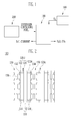
- the unit cell of the electricity generator 100 includes a membrane electrode assembly (MEA) 110 and a separator plate 130 supplying hydrogen containing gas and oxygen containing gas to an anode electrode 114 and a cathode electrode 116, respectively.
- the membrane electrode assembly 110 includes an ionic conductive polymer membrane 112 having selective ion permeability, and the anode electrode 114 and the cathode electrode 116 provided on opposite sides of the ionic conductive polymer membrane 112.
- the ionic conductive polymer membrane 112 has an ion exchange function of supplying a hydrogen ion generated from a catalyst layer (not shown) of the anode electrode 114 to the catalyst layer of the cathode electrode 116, and a function of preventing the hydrogen containing fuel from permeating therein.
- the ionic conductive polymer membrane 112 has a thickness in the range of about 50 ⁇ m to 200 ⁇ m.
- the ionic conductive polymer membrane 112 includes a perfluorosulfonate resin film made of a perfluorosulfonate resin (NAFION TM ), a film having a porous polytetrafluoro ethylene thin film support coated with perfluorinated sulfonic acid or the like resin solution, or a film having a porous nonconductive polymer support coated with positive ion exchange resin and inorganic silicate.
- NAFION TM perfluorosulfonate resin
- the electrode e.g., the cathode electrode 116 includes a first porous supporting layer such as carbon paper, a first diffusion layer for a catalyst material, and a first catalyst layer which are stacked in sequence on the first porous supporting layer.
- the first porous supporting layer serves as both an inlet channel for oxygen, supplied through an oxygen supplying channel 134 formed in a side of the separator plate 130, and also an outlet channel for water (H 2 O) that is a byproduct from an electrochemical reaction performed in the first catalyst layer (to be described later).
- H 2 O water
- the first diffusion layer is interposed between the first porous supporting layer and the first catalyst layer, and allows oxygen supplied from the oxygen supplying channel 134 to be uniformly diffused through the first catalyst layer, thereby discharging water, based on the reduction reaction, to the first porous supporting layer.
- the anode electrode 114 includes a second porous supporting layer such as carbon paper, a second diffusion layer for a catalyst material, and a second catalyst layer which are stacked in sequence on the second porous supporting layer.
- the second porous supporting layer serves as both an inlet channel for the hydrogen containing fuel supplied through a fuel supplying channel 132 formed in a side of the separator plate 130, and also an outlet channel for carbon dioxide (CO 2 ) that is a byproduct from an electrochemical reaction performed in the second catalyst layer (to be described later).
- CO 2 carbon dioxide
- the hydrogen containing fuel supplied via the second porous supporting layer and the second diffusion layer is oxidized by the following reaction formula (2).
- the second diffusion layer is interposed between the second porous supporting layer and the second catalyst layer, and allows the hydrogen containing fuel supplied from the fuel supplying channel 132 to be uniformly diffused through the second catalyst layer, thereby discharging carbon dioxide based on the oxidation reaction to the second porous supporting layer.
- the anode electrode 114 generates carbon dioxide, six hydrogen ions, and six electrons by the reaction between methanol and water (oxidation reaction).
- the hydrogen ions are transferred to the cathode electrode 116 via the polymer membrane 112, for example, via a hydrogen ion exchange membrane.
- the cathode electrode 116 generates water by reaction among the hydrogen ions, the electrons and oxygen.
- the reaction between the methanol and oxygen produces water and carbon dioxide.
- gaskets 120A and 120B are provided between the ionic conductive polymer membrane 112 of the membrane electrode assembly 110 and the separator plates 130.
- the gaskets 120A and 120B are provided to prevent the hydrogen containing fuel supplied to the anode electrode 114 through the fuel supplying channel 132 of the separator plate 130 and the oxygen supplied to the cathode electrode 116 through the oxygen supplying channel 134 of the separator plate 130 leaking through between the ionic conductive polymer membrane 112 and the separator plate 130.
- the gasket 120A and 120B are provided to enclose each edge of the anode and cathode electrodes 114 and 116 between the ionic conductive polymer membrane 112 of the membrane electrode assembly 110 and the separator plate 130.
- the gaskets may include elastomeric material to achieve the aforesaid sealing function.
- At least one of the gaskets is used as a voltage measuring gasket 120B, which not only prevents fluid leakage but also measures a voltage generated in the unit cell.
- the voltage measuring gasket 120B is provided facing the anode electrode of the membrane electrode assembly 110, but is not limited thereto. Alternatively, the voltage measuring gasket may be provided facing the cathode electrode, or on opposite sides of the membrane electrode assembly 110.
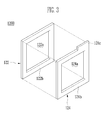
- the voltage measuring gasket 120B includes an elastomeric, electrically nonconductive first frame 122, and an electrically conductive second frame 124 that can be used for measuring cell voltage.
- each of the first frame 122 and the second frame 124 includes an opening 122a, 124a that allows the anode electrode to be in contact with the surface of the fuel supplying channel 132 of the separator plate 130, and a rim 122b, 124b that surrounds the opening 122a, 124a.
- the rims 122b, 124b are preferably formed to enclose the edge of the anode electrode.
- the second frame 124 is provided with a voltage measuring terminal 124c outwardly extended from the rim 124b.
- the first frame 122 is located in a position contacting the separator plate 130, and the second frame 124 is located in a position contacting the conductive polymer membrane 112. In doing so, current based on the electrochemical reaction in the membrane electrode assembly 110 can flow to the second frame 124.
- the voltage measuring gasket 120B is provided between one side of the ionic conductive polymer membrane 112 and one separator plate
- an ordinary gasket 120A is provided between the other side of the ionic conductive polymer membrane 112 and another separator plate.
- the voltage measuring gasket 120B according to the present invention may be provided on the opposite sides of the conductive polymer membrane 112.
- the separator plate 130 In the separator plate 130, the fuel supplying channel 132 through which the hydrogen containing fuel flows is placed in one side of the separator plate 130 facing the anode electrode 114 of the membrane electrode assembly 100, and the oxygen supplying channel 134 through which oxygen containing gas flows is placed in the other side of the separator plate 130 facing the cathode electrode 116 of the membrane electrode assembly 100. Further, the separator plate 130 includes a refrigerant channel 136 through which a refrigerant flows to dissipate heat generated in the foregoing electrochemical reaction.
- a voltmeter (not shown) is connected to the voltage measuring terminal 124c provided in the second frame of the voltage measuring gasket 120B, thereby measuring the voltage of each unit cell.
- the voltmeter generally includes a voltage probe which is electrically connected to the voltage measuring terminal 124c, and a voltage indicator to indicate the voltage of the unit cell measured by the voltage probe.
- the fuel feeder 200 supplies low-concentration hydrogen containing fuel, e.g., methanol diluted with water and having a predetermined concentration, to the electricity generator 100.
- the hydrogen containing fuel is readily supplied to the unit cell, particularly, to the anode electrode 114 of the membrane electrode assembly 110 through the fuel supplying channel 132 of the separator plate 130.
- the oxygen feeder 300 supplies oxygen to the electricity generator 100.
- oxygen is supplied to the unit cell, particularly, to the cathode electrode 116 of the membrane electrode assembly 110 through the oxygen supplying channel 134 of the separator plate 134.
- the hydrogen containing fuel supplied via the second porous supporting layer and the second diffusion layer is oxidized in the second catalyst layer, thereby generating hydrogen ions, electrons and carbon dioxide.
- the hydrogen ion is transferred to the first catalyst layer of the cathode electrode 116 via the ionic conductive polymer membrane 112, and carbon dioxide is discharged outside through the fuel supplying channel 132 of the separator plate 130 via the second porous supporting layer.
- the voltage probe of the voltmeter is electrically connected to the voltage measuring terminal 124c, thereby measuring the voltage generated by the foregoing chemical reaction in the unit cell.
- the normal operation of each unit cell is determined according to levels of the voltage measured by the voltmeter.
Landscapes
- Life Sciences & Earth Sciences (AREA)
- Engineering & Computer Science (AREA)
- Manufacturing & Machinery (AREA)
- Sustainable Development (AREA)
- Sustainable Energy (AREA)
- Chemical & Material Sciences (AREA)
- Chemical Kinetics & Catalysis (AREA)
- Electrochemistry (AREA)
- General Chemical & Material Sciences (AREA)
- Fuel Cell (AREA)
Applications Claiming Priority (2)
| Application Number | Priority Date | Filing Date | Title |
|---|---|---|---|
| KR20060003310 | 2006-01-11 | ||
| KR1020070001119A KR101380038B1 (ko) | 2006-01-11 | 2007-01-04 | 전압검출이 가능한 가스킷 및 이를 구비한 연료전지 시스템 |
Publications (1)
| Publication Number | Publication Date |
|---|---|
| EP1808922A1 true EP1808922A1 (fr) | 2007-07-18 |
Family
ID=37986824
Family Applications (1)
| Application Number | Title | Priority Date | Filing Date |
|---|---|---|---|
| EP07100382A Withdrawn EP1808922A1 (fr) | 2006-01-11 | 2007-01-11 | pile à combustible ayant un cadre d'étanchéité comprenant des contacts pour la mesure de tension |
Country Status (2)
| Country | Link |
|---|---|
| US (1) | US7927758B2 (fr) |
| EP (1) | EP1808922A1 (fr) |
Cited By (1)
| Publication number | Priority date | Publication date | Assignee | Title |
|---|---|---|---|---|
| NL2006266C2 (en) * | 2011-02-21 | 2012-08-22 | Hyet Holding B V | Membrane electrode assembly for fuel cell or redox flow battery. |
Families Citing this family (1)
| Publication number | Priority date | Publication date | Assignee | Title |
|---|---|---|---|---|
| SE2350842A1 (en) * | 2023-07-05 | 2025-01-06 | Powercell Sweden Ab | Membrane electrode assembly |
Citations (8)
| Publication number | Priority date | Publication date | Assignee | Title |
|---|---|---|---|---|
| JPS6010565A (ja) * | 1983-06-30 | 1985-01-19 | Fuji Electric Corp Res & Dev Ltd | 燃料電池 |
| JPH06267578A (ja) * | 1993-03-16 | 1994-09-22 | Toshiba Corp | 燃料電池 |
| JPH07282832A (ja) * | 1994-04-14 | 1995-10-27 | Toyota Motor Corp | 燃料電池の駆動装置 |
| WO2000026979A1 (fr) * | 1998-10-30 | 2000-05-11 | Siemens Aktiengesellschaft | Element de cadre pour pile a combustible a membrane electrolytique polymere, a structure stratifiee et procede permettant de le produire |
| EP1296395A1 (fr) | 2000-06-27 | 2003-03-26 | Nok Corporation | Joint statique pour pile a combustible |
| US20050191537A1 (en) | 2004-02-27 | 2005-09-01 | Belchuk Mark A. | Fuel cell gasket having an integrated sensor |
| FR2871944A1 (fr) * | 2004-06-16 | 2005-12-23 | Air Liquide | Systeme de surveillance d'un ensemble de cellules electrochimiques et dispositif de realisation |
| EP1768204A2 (fr) * | 2005-09-21 | 2007-03-28 | ElringKlinger AG | Joint d'étanchéité pour empilement de piles à combustible et procédé de fabrication |
Family Cites Families (7)
| Publication number | Priority date | Publication date | Assignee | Title |
|---|---|---|---|---|
| JPH087911A (ja) | 1994-06-22 | 1996-01-12 | Osaka Gas Co Ltd | リン酸型燃料電池の不良セル検出方法 |
| JPH09199147A (ja) | 1996-01-12 | 1997-07-31 | Toshiba Corp | 燃料電池発電装置 |
| JP3596761B2 (ja) * | 2000-12-27 | 2004-12-02 | 松下電器産業株式会社 | 高分子電解質型燃料電池 |
| JP2003123801A (ja) | 2001-10-16 | 2003-04-25 | Matsushita Electric Ind Co Ltd | 高分子電解質型積層燃料電池 |
| JP2005019042A (ja) | 2003-06-24 | 2005-01-20 | Matsushita Electric Ind Co Ltd | 燃料電池スタックおよび燃料電池スタックの制御方法 |
| JP4381759B2 (ja) | 2003-09-19 | 2009-12-09 | 本田技研工業株式会社 | セパレータおよび燃料電池 |
| JP2005183308A (ja) | 2003-12-22 | 2005-07-07 | Honda Motor Co Ltd | 燃料電池用電圧検出装置の接続異常検出方法及び燃料電池の異常検出方法 |
-
2007
- 2007-01-08 US US11/651,830 patent/US7927758B2/en not_active Expired - Fee Related
- 2007-01-11 EP EP07100382A patent/EP1808922A1/fr not_active Withdrawn
Patent Citations (8)
| Publication number | Priority date | Publication date | Assignee | Title |
|---|---|---|---|---|
| JPS6010565A (ja) * | 1983-06-30 | 1985-01-19 | Fuji Electric Corp Res & Dev Ltd | 燃料電池 |
| JPH06267578A (ja) * | 1993-03-16 | 1994-09-22 | Toshiba Corp | 燃料電池 |
| JPH07282832A (ja) * | 1994-04-14 | 1995-10-27 | Toyota Motor Corp | 燃料電池の駆動装置 |
| WO2000026979A1 (fr) * | 1998-10-30 | 2000-05-11 | Siemens Aktiengesellschaft | Element de cadre pour pile a combustible a membrane electrolytique polymere, a structure stratifiee et procede permettant de le produire |
| EP1296395A1 (fr) | 2000-06-27 | 2003-03-26 | Nok Corporation | Joint statique pour pile a combustible |
| US20050191537A1 (en) | 2004-02-27 | 2005-09-01 | Belchuk Mark A. | Fuel cell gasket having an integrated sensor |
| FR2871944A1 (fr) * | 2004-06-16 | 2005-12-23 | Air Liquide | Systeme de surveillance d'un ensemble de cellules electrochimiques et dispositif de realisation |
| EP1768204A2 (fr) * | 2005-09-21 | 2007-03-28 | ElringKlinger AG | Joint d'étanchéité pour empilement de piles à combustible et procédé de fabrication |
Cited By (2)
| Publication number | Priority date | Publication date | Assignee | Title |
|---|---|---|---|---|
| NL2006266C2 (en) * | 2011-02-21 | 2012-08-22 | Hyet Holding B V | Membrane electrode assembly for fuel cell or redox flow battery. |
| WO2012115510A1 (fr) * | 2011-02-21 | 2012-08-30 | Hyet Holding B.V. | Ensemble d'électrodes à membrane pour pile à combustible ou batterie redox à circulation |
Also Published As
| Publication number | Publication date |
|---|---|
| US20070160882A1 (en) | 2007-07-12 |
| US7927758B2 (en) | 2011-04-19 |
Similar Documents
| Publication | Publication Date | Title |
|---|---|---|
| US8877405B2 (en) | Fuel cell including membrane electrode assembly to maintain humidity condition | |
| US20100028736A1 (en) | Hybrid Ionomer Electrochemical Devices | |
| JPWO2007063826A1 (ja) | 燃料電池システム | |
| CN101385174B (zh) | 膜催化剂层组件、膜电极组件以及高分子电解质型燃料电池 | |
| CN214254475U (zh) | 燃料电池及用于燃料电池的重复部件 | |
| CN100544085C (zh) | 能够测量电压的衬垫和具有该衬垫的燃料电池系统 | |
| US20150064581A1 (en) | Hybrid Ionomer Electrochemical Devices | |
| EP4343031A2 (fr) | Séparateur et électrolyseur d'eau | |
| KR100748304B1 (ko) | 연료전지 시스템 및 이에 사용하기 위한 바이폴라플레이트와 단위전지 | |
| EP4343030A2 (fr) | Électrolyseur d'eau | |
| EP2190052B1 (fr) | Système de pile à combustible | |
| US7927758B2 (en) | Gasket being capable of measuring voltage and fuel cell system having the same | |
| EP2405515A1 (fr) | Séparateur pour pile à combustible et pile à combustible le comprenant | |
| KR100646953B1 (ko) | 평판형 연료전지 시스템 | |
| US20250246648A1 (en) | Fuel cell | |
| JP2005302320A (ja) | 燃料電池の検査方法 | |
| KR20020056135A (ko) | 연료전지의 연료공급장치 | |
| KR20020056137A (ko) | 연료전지의 연료공급장치 및 그 방법 | |
| KR101065380B1 (ko) | 연료 전지 시스템 및 이에 사용되는 스택 | |
| KR100646951B1 (ko) | 평판형 연료전지 시스템 | |
| KR100646952B1 (ko) | 평판형 연료전지 시스템 | |
| KR100748347B1 (ko) | 기액분리장치 및 이를 갖는 연료전지 시스템 | |
| KR100675691B1 (ko) | 연료전지의 연료온도유지장치 및 그 방법 | |
| KR20070040248A (ko) | 도전성 전극막 조립체 및 이를 구비한 연료전지 시스템 | |
| JP2013114931A (ja) | 固体高分子型燃料電池用電解質膜・電極構造体 |
Legal Events
| Date | Code | Title | Description |
|---|---|---|---|
| PUAI | Public reference made under article 153(3) epc to a published international application that has entered the european phase |
Free format text: ORIGINAL CODE: 0009012 |
|
| 17P | Request for examination filed |
Effective date: 20070111 |
|
| AK | Designated contracting states |
Kind code of ref document: A1 Designated state(s): AT BE BG CH CY CZ DE DK EE ES FI FR GB GR HU IE IS IT LI LT LU LV MC NL PL PT RO SE SI SK TR |
|
| AX | Request for extension of the european patent |
Extension state: AL BA HR MK YU |
|
| AKX | Designation fees paid |
Designated state(s): DE FR GB |
|
| RAP1 | Party data changed (applicant data changed or rights of an application transferred) |
Owner name: SAMSUNG SDI CO., LTD. |
|
| 17Q | First examination report despatched |
Effective date: 20090717 |
|
| GRAP | Despatch of communication of intention to grant a patent |
Free format text: ORIGINAL CODE: EPIDOSNIGR1 |
|
| RIC1 | Information provided on ipc code assigned before grant |
Ipc: H01M 8/10 20060101AFI20151215BHEP |
|
| INTG | Intention to grant announced |
Effective date: 20160108 |
|
| STAA | Information on the status of an ep patent application or granted ep patent |
Free format text: STATUS: THE APPLICATION IS DEEMED TO BE WITHDRAWN |
|
| 18D | Application deemed to be withdrawn |
Effective date: 20160519 |