EP1809459B1 - Machine dotee d'une pluralite d'actionneurs - Google Patents
Machine dotee d'une pluralite d'actionneurs Download PDFInfo
- Publication number
- EP1809459B1 EP1809459B1 EP05789537A EP05789537A EP1809459B1 EP 1809459 B1 EP1809459 B1 EP 1809459B1 EP 05789537 A EP05789537 A EP 05789537A EP 05789537 A EP05789537 A EP 05789537A EP 1809459 B1 EP1809459 B1 EP 1809459B1
- Authority
- EP
- European Patent Office
- Prior art keywords
- machine according
- actuating
- control unit
- actuating device
- mould
- Prior art date
- Legal status (The legal status is an assumption and is not a legal conclusion. Google has not performed a legal analysis and makes no representation as to the accuracy of the status listed.)
- Expired - Lifetime
Links
Images







Classifications
-
- B—PERFORMING OPERATIONS; TRANSPORTING
- B29—WORKING OF PLASTICS; WORKING OF SUBSTANCES IN A PLASTIC STATE IN GENERAL
- B29C—SHAPING OR JOINING OF PLASTICS; SHAPING OF MATERIAL IN A PLASTIC STATE, NOT OTHERWISE PROVIDED FOR; AFTER-TREATMENT OF THE SHAPED PRODUCTS, e.g. REPAIRING
- B29C43/00—Compression moulding, i.e. applying external pressure to flow the moulding material; Apparatus therefor
- B29C43/32—Component parts, details or accessories; Auxiliary operations
- B29C43/36—Moulds for making articles of definite length, i.e. discrete articles
-
- B—PERFORMING OPERATIONS; TRANSPORTING
- B29—WORKING OF PLASTICS; WORKING OF SUBSTANCES IN A PLASTIC STATE IN GENERAL
- B29C—SHAPING OR JOINING OF PLASTICS; SHAPING OF MATERIAL IN A PLASTIC STATE, NOT OTHERWISE PROVIDED FOR; AFTER-TREATMENT OF THE SHAPED PRODUCTS, e.g. REPAIRING
- B29C43/00—Compression moulding, i.e. applying external pressure to flow the moulding material; Apparatus therefor
- B29C43/02—Compression moulding, i.e. applying external pressure to flow the moulding material; Apparatus therefor of articles of definite length, i.e. discrete articles
- B29C43/04—Compression moulding, i.e. applying external pressure to flow the moulding material; Apparatus therefor of articles of definite length, i.e. discrete articles using movable moulds
- B29C43/06—Compression moulding, i.e. applying external pressure to flow the moulding material; Apparatus therefor of articles of definite length, i.e. discrete articles using movable moulds continuously movable in one direction, e.g. mounted on chains, belts
- B29C43/08—Compression moulding, i.e. applying external pressure to flow the moulding material; Apparatus therefor of articles of definite length, i.e. discrete articles using movable moulds continuously movable in one direction, e.g. mounted on chains, belts with circular movement, e.g. mounted on rolls, turntables
-
- B—PERFORMING OPERATIONS; TRANSPORTING
- B29—WORKING OF PLASTICS; WORKING OF SUBSTANCES IN A PLASTIC STATE IN GENERAL
- B29C—SHAPING OR JOINING OF PLASTICS; SHAPING OF MATERIAL IN A PLASTIC STATE, NOT OTHERWISE PROVIDED FOR; AFTER-TREATMENT OF THE SHAPED PRODUCTS, e.g. REPAIRING
- B29C43/00—Compression moulding, i.e. applying external pressure to flow the moulding material; Apparatus therefor
- B29C43/02—Compression moulding, i.e. applying external pressure to flow the moulding material; Apparatus therefor of articles of definite length, i.e. discrete articles
- B29C43/14—Compression moulding, i.e. applying external pressure to flow the moulding material; Apparatus therefor of articles of definite length, i.e. discrete articles in several steps
- B29C43/146—Compression moulding, i.e. applying external pressure to flow the moulding material; Apparatus therefor of articles of definite length, i.e. discrete articles in several steps for making multilayered articles
-
- B—PERFORMING OPERATIONS; TRANSPORTING
- B29—WORKING OF PLASTICS; WORKING OF SUBSTANCES IN A PLASTIC STATE IN GENERAL
- B29C—SHAPING OR JOINING OF PLASTICS; SHAPING OF MATERIAL IN A PLASTIC STATE, NOT OTHERWISE PROVIDED FOR; AFTER-TREATMENT OF THE SHAPED PRODUCTS, e.g. REPAIRING
- B29C43/00—Compression moulding, i.e. applying external pressure to flow the moulding material; Apparatus therefor
- B29C43/32—Component parts, details or accessories; Auxiliary operations
- B29C2043/3272—Component parts, details or accessories; Auxiliary operations driving means
- B29C2043/3277—Component parts, details or accessories; Auxiliary operations driving means for rotatable suports, e.g. carousels, drums
-
- B—PERFORMING OPERATIONS; TRANSPORTING
- B29—WORKING OF PLASTICS; WORKING OF SUBSTANCES IN A PLASTIC STATE IN GENERAL
- B29C—SHAPING OR JOINING OF PLASTICS; SHAPING OF MATERIAL IN A PLASTIC STATE, NOT OTHERWISE PROVIDED FOR; AFTER-TREATMENT OF THE SHAPED PRODUCTS, e.g. REPAIRING
- B29C43/00—Compression moulding, i.e. applying external pressure to flow the moulding material; Apparatus therefor
- B29C43/32—Component parts, details or accessories; Auxiliary operations
- B29C2043/3272—Component parts, details or accessories; Auxiliary operations driving means
- B29C2043/3283—Component parts, details or accessories; Auxiliary operations driving means for moving moulds or mould parts
-
- B—PERFORMING OPERATIONS; TRANSPORTING
- B29—WORKING OF PLASTICS; WORKING OF SUBSTANCES IN A PLASTIC STATE IN GENERAL
- B29C—SHAPING OR JOINING OF PLASTICS; SHAPING OF MATERIAL IN A PLASTIC STATE, NOT OTHERWISE PROVIDED FOR; AFTER-TREATMENT OF THE SHAPED PRODUCTS, e.g. REPAIRING
- B29C43/00—Compression moulding, i.e. applying external pressure to flow the moulding material; Apparatus therefor
- B29C43/32—Component parts, details or accessories; Auxiliary operations
- B29C43/58—Measuring, controlling or regulating
- B29C2043/5833—Measuring, controlling or regulating movement of moulds or mould parts, e.g. opening or closing, actuating
-
- B—PERFORMING OPERATIONS; TRANSPORTING
- B29—WORKING OF PLASTICS; WORKING OF SUBSTANCES IN A PLASTIC STATE IN GENERAL
- B29C—SHAPING OR JOINING OF PLASTICS; SHAPING OF MATERIAL IN A PLASTIC STATE, NOT OTHERWISE PROVIDED FOR; AFTER-TREATMENT OF THE SHAPED PRODUCTS, e.g. REPAIRING
- B29C33/00—Moulds or cores; Details thereof or accessories therefor
- B29C33/20—Opening, closing or clamping
-
- B—PERFORMING OPERATIONS; TRANSPORTING
- B29—WORKING OF PLASTICS; WORKING OF SUBSTANCES IN A PLASTIC STATE IN GENERAL
- B29L—INDEXING SCHEME ASSOCIATED WITH SUBCLASS B29C, RELATING TO PARTICULAR ARTICLES
- B29L2031/00—Other particular articles
- B29L2031/56—Stoppers or lids for bottles, jars, or the like, e.g. closures
- B29L2031/565—Stoppers or lids for bottles, jars, or the like, e.g. closures for containers
Definitions
- the present invention relates to an operating machine in which at least one actuator acts and actuating apparatuses which actuate moulding members in an moulding machine and a control system of moulding machine.
- the invention refers in particular, but not exclusively, to the compression moulding of plastics for obtaining objects such as caps suitable for being associated with containers.
- the term "punch” indicates the male half mould and the term “die” indicates the female or cavity half mould.
- US 2621363 discloses an automatic machine for moulding articles from thermosetting or thermoplastic material.
- the machine comprises a preliminary mould in which a semi-moulding is obtained from a predetermined quantity of moulding material and a main mould in which the moulding operation of the semi-moulding is completed.
- the machine further comprises a valve which controls the supply of oil to and its discharge from the cylinders for actuating the upper and lower members of the main mould and the cylinder for the plunger of the preliminary mould.
- the valve comprises an angularly movable valve member which is arranged within a casing and is angularly movable therein with a snap-action between two extreme positions. When the valve member is in the first position, the plungers of the above-mentioned cylinders are projected. When the valve member is in the second position, the plungers of the above-mentioned cylinders are retracted.
- GB 1052337 discloses a machine tool comprising a rotatable support member or turret having a radial flange which forms a table and which rotates about the axis of a vertical column on a base member.
- the table carries a number of independently rotatable work spindles.
- the turret which is externally square in plan, carries a vertical and a horizontal slide member on each face, which carry tool holders.
- To the upper end of the column is secured a drum-type cam member with peripheral grooves in which are located cam followers which during rotation of the turret effect longitudinal and transverse movements of the slides and in consequence the holders and cutting tools.
- the transverse movement of the slide is effected through a bell-crank lever.
- the turret is driven by an electric motor through gearing and the work spindles are driven by individual motors.
- Apparatuses comprising moulds for the compression moulding of plastics are known comprising a die provided with a cavity in which a certain quantity of plastics is inserted in a pasty state, and a punch suitable for compressing the plastic material inside the cavity.
- the cavity and the punch are shaped in such a manner as to give the plastics a shape corresponding to the object to be obtained.
- the die defines an external surface of the object and the punch defines an internal surface of the object.
- the die and the punch are moved towards and away from each other by actuators that may be of a mechanical or hydraulic type.
- the hydraulic actuators comprise a cylinder inside which a piston is movable driven by pressurised oil that controls the movement of the punch and/or the die.
- a drawback of the hydraulic actuators is that they involve significant system and structural complication, in particular if a plurality of moulds fitted to the same rotatable turntable is provided.
- a further drawback of the hydraulic actuators is that they have a follower organ, the speed of which is not easily controllable.
- the obtained caps may have unacceptable drawbacks, for example burrs, due to asymmetrical and nonuniform flows of the plastic in the mould.
- a still further drawback of the hydraulic actuators is that it is necessary to constantly control the fluid contained inside them and intervene in the case of losses and/or leaks from the latter.
- hydraulic actuators furthermore leads to the risk that a certain quantity of oil may come into contact with the plastics being moulded, for example through an oil leak or through the evaporation of particles of oil into the air surrounding the moulding environment, thereby causing contamination and a possible deterioration to the formed object.
- the mechanical actuators may comprise a cam, which controls the movement of the punch or of the die.
- the mechanical actuators thus have numerous drawbacks inasmuch as they need very expensive components and require extremely precise assembly of these components.
- actuators are rather stiff because they do not allow simple adjustment of the stroke that the punch, or the die, has to perform and of the speed with which the stroke is performed. This adjustment can in fact be obtained only by replacing parts of the actuators.
- the mechanical actuators furthermore greatly suffer from wear to the components that constitute them, so after prolonged operation they tend to be imprecise.
- the mechanical actuators are worn they are not able to ensure preset pressure between the punch and the die, which may cause undesired escapes of material from the die.
- shock-absorbing devices can be provided interposed between the actuator and the die and/or the punch that enable the stress to be maintained substantially constant to which the punch, the die and the organs for their operation are subjected.
- the shock-absorbing devices prevent the great stress that is generated from damaging, possibly irreparably, the mould.
- shock-absorbing devices furthermore enable to a certain extent differences between the actual stroke and the theoretical stroke of the actuators to be compensated, these differences being for example due to the wear that affects the cams.
- the shock-absorbing devices may comprise a pneumatic cylinder interposed between the die and/or the punch and the respective actuator.
- the known apparatuses comprise a rotatable turntable to which a plurality of the aforementioned dies is fixed, for example arranged in angularly equidistant positions.
- Each mould is operated by an actuator with which a control unit is associated.
- each mould comprises a punch fixed to a frame of the turntable and a die that is fixed to a movable part of an actuator that moves the die towards and away from the punch.
- each mould is opened in such a way that a formed cap can be extracted from it and a preset quantity of plastics in the pasty state is inserted inside the mould to obtain a further cap.
- the mould is closed to obtain the moulding of a cap and the stabilisation of the form of the aforementioned cap.
- phase of extraction of the formed cap and the phase of insertion of the pasty plastics require rather a limited time during which the turntable performs a rotation corresponding to an angle of a few tens of degrees, for example about 20 degrees.
- a drawback of the apparatuses disclosed above consists of the fact that they are not very cheap, because of the high cost of the actuators and of the control units arranged to regulate their operation.
- An object of the invention is to improve the apparatuses for compression moulding of plastics.
- Another object of the invention is to obtain an apparatus for compression moulding of plastics that is rather cheap.
- a further object of the invention is to obtain an apparatus for compression moulding of plastics that enables operation of the moulds to be effectively controlled.
- the actuating devices control the opening and closing of mould means for the compression moulding of plastics.
- switching means enables one or more control units to be installed to control a greater number of actuating means rather than one control unit for each actuating device, as occurs in the apparatuses according to the state of the art.
- an apparatus 20 for the compression moulding of plastics for obtaining caps 2 comprising a turntable 21 with which a plurality of moulds 1 is associated.
- Each mould 1 comprises a die 3 provided with a cavity 5 suitable for defining an external surface of the caps 2, and a punch 4 arranged to press the plastics into the cavity 5 and suitable for defining an internal surface of the caps 2.
- the punch 4 is fixed to a support element 14 and remains stationary during operation of the mould 1.
- Each mould 1 is associated with an actuating device 15, which will be disclosed in greater detail below, which controls, through a movable member 7, the movement of the die 3 towards and away from the punch 4, in the direction indicated by the arrow F.
- the turntable 21 is rotatable in the direction indicated by the arrow R.
- the moulds 1 are connected to the turntable 21 in such a way as to be arranged at angular distances of a constant amplitude.
- a transducer - not shown - is furthermore associated that is arranged to detect the stroke performed by the movable member 7 of the actuating device 15, to which the die 3 is fixed.
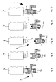
- FIGS 3 to 7 show some of the moulds associated with the turntable 21, these moulds being indicated by the numeric references 1a, 1b, 1c, 1d, 1e.
- Each mould 1a, 1b, 1c, 1d, 1e is provided with a respective actuating device 15a, 15b, 15c, 15d, 15e.
- Figures 3 and 4 respectively show the moulds 1a, 1b in a closing position A, in which the plastics contained therein is moulded in such a way as to obtain a cap 2.
- Figures 5 and 6 respectively show the moulds 1c and 1d in an opening position B in which a formed cap 2 is extracted from the respective mould, and a further dose of plastics in pasty state is inserted into the aforementioned mould.
- Figure 7 shows the mould 1e in a subsequent closing position A1, corresponding to the closing position A.
- Each mould 1 goes from the closing position A to the opening position B and then to the subsequent closing position A1 whilst the turntable 21 rotates by an angle of a preset amplitude.
- each mould 1 is kept in the closing position A, A1 in such a way as to obtain, after moulding, stabilisation of the form of the cap 2 contained therein.
- the seal promoting element comprises a disc in plastics that is positioned inside the cap in contact with a base wall off the latter.
- Figures 8 to 12 show the moulds 1a, 1b, 1c, 1d, 1e after the turntable 21 has performed a half advance step.
- the mould 1a is still in the closing position A
- the mould 1b is being transferred from the closing position A to the opening position B
- the mould 1c is in the opening position B
- the cap 2 is removed from the punch 5 and a further dose of plastics is inserted inside the die 3
- the mould 1d is being transferred from the opening position B to the closing position A1
- the mould 1e lastly, is in the closing position A1.
- the apparatus 20 comprises a control unit 18 arranged to control the operation of the actuating devices 15.
- the control unit 18 can be arranged in a remote position in relation to the actuating devices 15.
- the control unit 18 may be a control logic unit. Alternatively, a plurality of control units may be provided for controlling a larger number of actuating devices 15.
- each control unit can be dedicated to control a specific operation.
- the apparatus furthermore comprises switching means 22 arranged to selectively connect each actuating device 15 to the control unit 18.
- the apparatus can furthermore comprise supply means that is not shown arranged to supply the actuating devices 15, enabling its operation.
- the supply means may comprise connectors and/or switches arranged to physically connect the actuators to delivery means of electric power.
- the aforementioned connectors/switches also disconnect the actuators from the delivery means of electric power.
- the supply means materially constitutes circuit components that connect and disconnect the actuators from the delivery means of electric power.
- the supply means comprises a plurality of supply units, each supply unit being arranged in the proximity of a corresponding actuating device 15.
- the switching means can selectively connect each supply unit to a respective actuating device 15.
- the supply means can comprise a single supply unit arranged in a remote position in relation to the actuating devices 15.
- the supply unit can be integrated into the control unit 18.
- the supply unit can be arranged in a remote position in relation to the control unit 18.
- the switching means 22 comprises first switching means 23 suitable for selectively connecting the actuating devices 15 to the control unit 18 that regulates the supply of each actuating device 15.
- the switching means 22 furthermore comprises second switching means 24 suitable for selectively connecting the transducers associated with the actuating devices 15 to the control unit 18.
- the aforementioned transducers detect the stroke performed by the movable member 7 of each actuating device 15 and communicate it to the control unit 18 which, on the basis of this information, further operates the movable member 7 or stops it by intervening on the supply of the respective actuating device 15.
- the apparatus furthermore comprises a position transducer 25 associated with the turntable 21 and suitable for communicating to the control unit 18 the position of the turntable 21 at each instant of the operating cycle.
- the switching means 22 connects each actuating device 15 to the control unit 18 whereas the actuating device 15 performs, fixed relative to the turntable 21, a rotation corresponding to a preset angular interval.
- each actuating device 15 is operated, during a period of time in which it travels, fixed relative to the turntable 21 said preset angular interval in such a way as to pass from an initial configuration to a final configuration.
- the switching means 22 can simultaneously connect a group of actuating devices 15a, 15b, 15c, 15d, 15e rather than a single actuating device 15 to the control unit 18.
- the group of actuating devices 15a, 15b, 15c, 15d, 15e can occupy a sector S of the turntable 1 having a certain angular amplitude.
- the switching means 22 furthermore interrupts the connection between each actuating device 15 and the control unit 18 for a further interval of time during which the actuating device 15 travels, fixed relative to the turntable 21, a further angular interval of preset amplitude.
- each actuating device 15 is not operated whilst the turntable 21 travels the angular interval and thus maintains the same configuration during the entire interval of time.
- the further angular interval corresponds to an angle that is substantially explementary to the angle corresponding to the aforementioned angular interval.
- each actuating device 15 is connected to the control unit 18 whilst it travels a certain angular interval, the connection thus being interrupted whilst the turntable 21 finishes making a revolution around its own axis.
- each actuating device 15 can be operated between an initial configuration and a final configuration.
- each actuating device 15 is connected to the control unit 18 whilst it traverses each of the active intervals.
- connection between each actuating device 15 and the control unit 18 is thus interrupted in each further interval interposed between two active consecutive intervals.
- the apparatus 1 is provided with one or more control units that are able to control a greater number of actuating devices 15 owing to the presence of the switching means 22.
- the apparatus 1 is much cheaper than the known apparatuses, inasmuch as it is not necessary to install a control unit for each actuating device.
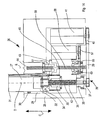
- the actuating devices 15 may comprise electromechanical actuating devices 26.
- the electromechanical actuating devices 26 are provided with a movable connecting body 27 at an end 31 of which the die 3 is fixed.
- Similar electromechanical actuating devices can operate the punch 4 by means of a further connecting body.
- the connecting body 27 is received in a space 29 obtained inside a housing 28 and is slidable in an advance direction C in such a way as to be able to be projected outside the housing 28 or be received inside it.
- the connecting body 27 is connected, at a second end 32 opposite the first end 31, to a lead nut 33.
- bearing means 34 is associated that enables the lead nut 33 to rotate around an axis D in relation to the movable connecting body 27.
- the lead nut 33 is centrally provided with a threaded through hole that is coaxial to the axis D and engages with first screw means 35 provided with a first thread 42.
- the first screw means 35 is arranged along the axis D inside the housing 28 and is rotatably connected to a support 36 so as to be rotatable around the axis D.
- the first screw means 35 is provided with a protruding portion 37 - not threaded - that projects through the support 36 outside the housing 28 and on which a first driven pulley 38 is splined.
- the first driven pulley 38 is connected by a first belt 39 to a first drive pulley 40 rotated by a first electric motor 41 installed inside the housing 28.
- the lead nut 33 is peripherally provided with toothing 45 that engages with a toothed wheel 43 fixed relative to the second screw means 44.
- the toothing 45 has an axial extent that is greater than the axial extent of the toothed wheel 43.
- the second screw means 44 is provided with a second thread 59 having a pitch that is greater than the pitch of the first thread 42.
- the second screw means 44 is arranged parallel to the first screw means 35.
- the second screw means 44 is rotatable around a further axis E and can move along the latter when it is rotated.
- the second screw means 44 is connected to a second driven pulley 55 which, by means of a second belt 56, is rotated by a second drive pulley 57 associated with a second electric motor 58.
- the second screw means 44 interacts with a first lead nut element 60, fixed relative to the second driven pulley 55, and with a second lead nut element 61 arranged opposite the first lead nut element 60 in relation to the toothed wheel 43 and fixed to the housing 28.
- first electric motor 41 and the second electric motor 58 are actuated in such a way as to rotate respectively the first screw means 35 by the first driven pulley 38, and the first lead nut element 60 by means of the second driven pulley 55.
- the first screw means 35 by rotating, forces the lead nut 33 and the connecting body 27 associated with it to move along the axis D.
- the second screw means 44 actuated by the first lead nut element 60, moves along the further axis E in the same advance direction as the lead nut 33, and simultaneously rotates so that the toothed wheel 43 drags the lead nut 33 to rotate.
- the lead nut 33 moves along the axis D and simultaneously rotates by screwing onto the first screw means 35.
- the lead nut 33 advances along the axis D at an advance speed defined by two distinct components.
- a first component is due to the movement given to the lead nut 33 by the first screw means 35 and a second component is due to the movement given to the lead nut 33 by the toothed wheel 43.
- the advance speed thus depends on the geometry of the first thread 42, on the geometry of the second thread 59, on the rotation speed of the first motor means 41 and on the rotation speed of the second motor means 58.
- the second electric motor 58 is deactivated by stopping rotation of the first lead nut element 60.
- the first electric motor 41 continues to rotate the first screw means 35, causing further movement of the lead nut 33 along the latter.
- the lead nut 33 shifts at a further advance speed having a value lower than the value of said advance speed, inasmuch as the further advance speed comprises solely a component due to the movement given to the lead nut 33 by the first screw means 35 and not also a further component due to the movement given to the lead nut 33 by the toothed wheel 43.
- the die 3 is initially advanced at a great speed in such a way as to reduce the time required for closing and opening the mould 1 and, subsequently, at a reduced speed that enables the caps 2 to be moulded in an effective and precise manner, thus reducing blows and dynamic shocks.
- electromechanical actuating devices 46 made according to a version.
- the electromechanical actuating devices 46 comprise a housing 28 inside which an electric motor 47 is installed that rotates a drive pulley 48.
- the drive pulley 48 is arranged outside the housing 28 and by means of a belt 49 actuates a driven pulley 50 that is fixed to screw means 51 provided with a thread 52.
- the screw means 51 is rotatably connected to a support 36 so as to be rotatable around its own longitudinal axis F.
- the thread 52 interacts with a further thread 54 obtained inside a lead nut element 53 fixed to a connecting body 27 that supports the die 3.
- the lead nut element 53 is slidable along the axis F inside a cavity 29 obtained in the housing 28.
- the electric motor 47 by means of the drive pulley 48 and the belt 49, rotates the driven pulley 50 and the screw means 51 connected thereto.
- electromechanical actuating devices 62 made according to a further version.
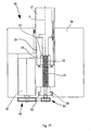
- the electromechanical actuating devices 62 comprise a connecting rod 63 having a first end 64 hinged on a crank pin 75 of a crankshaft 65 and a second end 66 hinged by means of a gudgeon 69 to an end 67 of a rod 70 provided with a further end 68 with which a die 3 of a mould 1 is associable, for example.
- the rod 70 is partially received inside a sleeve 71 that acts as a guide element for guiding the movement of the rod 70 parallel to its longitudinal axis, as indicated by the arrow L.
- the rod 70 therefore, actuated by the connecting rod 63 - as will be explained in greater detail below - moves the die 3 towards and away from a respective punch 4.
- the crankshaft 65 comprises a pair of pivots 72 rotatingly supported by respective bearings 73, on a casing 74 of the electromechanical actuating devices 62.
- toothed sector 76 is fixed having an angular extent greater than 180°.
- the toothed sector 76 is rotatable, as will be disclosed in greater detail below, around an axis X coinciding with the rotation axis of the pivots 72 of the crankshaft 65.
- the electromechanical actuating devices 62 furthermore comprises a further electric motor 77 provided with control means arranged to control an electric parameter of the electric motor 77.
- the electric motor 77 is provided with a shaft 78, supported by first bearing means 79 and by second bearing means 80, with which a screw gear 81 is associated that engages with the toothed sector 76.
- Figure 18 shows the rod 70 arranged in an operating configuration H, corresponding to the lower dead point, in which the die 3 is distanced from the corresponding punch 4 to enable the picking up of a formed object and the insertion inside the die 3 of a dose of plastics.
- Figure 19 shows the rod 70 arranged in a further operating configuration K, corresponding to the upper dead point, in which the die 3 cooperates with the respective punch 4 to perform the moulding of an object.
- the rod 70 is kept in the further operating configuration K even after moulding of the object to enable cooling and stabilisation of the form of the object.
- the electric motor 77 is rotated in a direction opposite the aforementioned preset direction, causing a corresponding rotation of the toothed sector 76 in a direction opposite that indicated by the arrow S. In this way, the rod 70 is returned to the operating configuration H.
- the electromechanical actuating devices 62 enable the rod 70 - and therefore the die 3, or the punch 4 that is associated therewith - to be operated at a variable speed.
- the electromechanical actuating devices 62 enable a low speed to be obtained - and a high moulding force - at a final phase of the stroke of the rod 70, and a high speed at an intermediate phase of the stroke of the rod 70, thus ensuring rapid closure of the mould 1.
- the speed of the die 3, or of the punch 4 is particularly high in the vicinity of a still further operating configuration M, shown in Figure 20 , in which the cranking is in the squaring position.
- the electric motor 77 and the respective control means are not stressed during the course of the phases of cooling and stabilisation of the form of an object, such phases being the longest-lasting in a work cycle of the apparatus.
- the interposition between the rod 70 and the die 3, or the punch, of shock-absorbing means which will be disclosed in greater detail below, enable a force to be exerted on the object contained in the mould during the phases of cooling and stabilisation of the form that is substantially constant despite the shrinkage due to cooling of the material with which the object was formed.
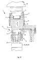
- mould 1 for the moulding of objects in plastics, for example caps 2.
- the mould 1 comprises a die 3 provided with a cavity 5 suitable for defining an external surface of the caps 2, and a punch 4 arranged to press the plastics in the cavity 5 and suitable for a defining an internal surface of the caps 2.
- the punch 4 is fixed relative to a support element 14 and remains stationary during operation of the mould 1.
- the mould 1 is connected at one of its ends to an actuating device, for example an electromechanical actuating device 26, 46, 62.
- an actuating device for example an electromechanical actuating device 26, 46, 62.
- the electromechanical actuating device 26, 46, 62 controls the movement of the die 3 towards and away from the punch 4 in the direction indicated by the arrow F.
- a head 9 At a free end 6 of a connecting body 27 of the electromechanical actuating device 26, 46, 62 there is fixed a head 9 by means of a screw 10.
- the head 9 is slidable inside a chamber 11 obtained in a base 8 of the die 3.
- the die 3 is connected to the base 8 by a threaded ring nut 13 that engages in a corresponding threat 16 obtained in a base zone 8 opposite a further zone of the base 8 in which the chamber 11 is obtained.
- conduit 12 is furthermore obtained that is arranged to connect the chamber 11 with an external environment, in particular with a system for supplying pressurised fluid, for example a gaseous fluid, in particular air.
- a maximum pressure conduit can be associated, that is not shown, that is arranged to enable the escape of the fluid from the chamber 11 if the pressure of the fluid has reached a preset threshold value.
- the chamber 11, the conduit 12 and the pressurised fluid act as shock-absorbing means 17 arranged to prevent excessively energetic interaction of the die 3 with the punch 4.
- the electromechanical actuating device 26, 46, 62 moves the punch 4 to and away from the die 3, which remains stationary during operation of the mould 1.
- shock-absorbing means 17 is positioned between the electromechanical actuating device 26, 46, 62 and the punch 4.
- the electromechanical actuating device 26, 46, 62 operates the die 3, whilst the punch 4 remains fixed.
- shock-absorbing means 17 is interposed between the punch 4 and the support element 14 rather than between the die-3 and the electromechanical actuating device 26, 46, 62.
- the shock-absorbing means 17 enables a virtually constant force to be maintained on the mould during the cooling phase of the objects, in particular, owing to the action of the pressurised fluid, the objects are maintained pressed despite the shrinkage caused by cooling of the plastics.
- Electromechanical actuating devices cooperating with shock-absorbing means 17 are particularly suitable for being used in combination with the control unit or units 18 and the switching means 22 disclosed with reference to Figures 1 to 12 .
- the switching means 22 can connect the electromechanical actuating devices to the control unit, or units 18, during the phase of supply of the mould with plastics and during the moulding phase.
- the switching means 22 can disconnect the electromechanical actuating devices from the control unit, or units 18, during the cooling phase, an appropriate clamping force being generated on the mould, in this operating configuration, by the shock-absorbing means 17.
- shock-absorbing means may not be provided. This is so in cases in which the electromechanical actuating devices are of the high-performance type.
- electric motor means with which the electromechanical actuating devices are provided may be controlled whilst powered up in order to exert a controllable force on the mould 1.
- the electromechanical actuating devices may comprise mechanically reversible electromechanical actuating devices that comprise a motion inlet and a motion outlet that can be mutually reversed during operation.
Landscapes
- Engineering & Computer Science (AREA)
- Mechanical Engineering (AREA)
- Moulds For Moulding Plastics Or The Like (AREA)
- Transmission Devices (AREA)
- Injection Moulding Of Plastics Or The Like (AREA)
- Mechanical Control Devices (AREA)
- Casting Or Compression Moulding Of Plastics Or The Like (AREA)
Abstract
Claims (19)
- Machine comprenant une pluralité de dispositifs actionneurs (15) supportés par des moyens rotatifs de carrousel (21), destinés à actionner des moyens de moulage (3, 4) et mobiles entre une position neutre (B) et une position de fonctionnement (A), des moyens de commande (18) destinés à commander lesdits dispositifs actionneurs (15), lesdits moyens de commande comprenant au moins une unité de commande (18), des moyens commutateurs (23) étant prévus pour raccorder de manière sélective ladite au moins une unité de commande (18) à au moins un dispositif actionneur (15a, 15b, 15c, 15d, 15e) de ladite pluralité de dispositifs actionneurs (15), caractérisée en ce que lesdits moyens commutateurs (23) relient ledit au moins un dispositif actionneur (15a, 15b, 15c, 15d, 15e) à au moins une unité de commande (18) pendant une plage de temps pendant laquelle ledit au moins un dispositif actionneur (15a, 15b, 15c, 15d, 15e) effectue, lorsqu'il est monté sur lesdits moyens de carrousel (21), une rotation d'une amplitude angulaire prédéterminée, et en ce que lesdits moyens commutateurs (23) interrompent la connexion entre ledit au moins un dispositif actionneur (15a, 15b, 15c, 15d, 15e) et ladite au moins une unité de commande (18) pendant une autre plage de temps pendant laquelle ledit au moins un dispositif actionneur (15a, 15b, 15c, 15d, 15e) effectue, lorsqu'il est monté sur lesdits moyens de carrousel (21), une autre rotation d'une amplitude angulaire prédéterminée.
- Machine selon la revendication 1, et comprenant en outre une pluralité d'unités de commande moins nombreuses que ladite pluralité de dispositifs actionneurs (15).
- Machine selon la revendication 2, dans laquelle chaque unité de commande (18) de ladite pluralité d'unités de commande commande une opération prédéterminée dudit au moins un dispositif actionneur (15a, 15b, 15c, 15d, 15e).
- Machine selon l'une quelconque des revendications 1 à 3, dans laquelle au moins une unité de commande (18) est installée dans une position éloignée par rapport auxdits dispositifs actionneurs (15).
- Machine selon l'une quelconque des revendications 1 à 4, dans laquelle ladite au moins une unité de commande (18) est une unité de commande logique.
- Machine selon l'une quelconque des revendications 1 à 5, et comprenant en outre au moins une unité d'alimentation pour relier lesdits dispositifs actionneurs (15) à des moyens fournisseurs d'énergie électrique.
- Machine selon la revendication 6, dans laquelle ladite au moins une unité d'alimentation est installée dans une position éloignée par rapport auxdits dispositifs actionneurs (15).
- Machine selon la revendication 6 ou 7, dans laquelle ladite au moins une unité d'alimentation est intégrée dans ladite au moins une unité de commande (18).
- Machine selon la revendication 6 ou 7, dans laquelle ladite au moins une unité d'alimentation est installée dans une position éloignée par rapport à ladite au moins une unité de commande (18).
- Machine selon la revendication 6, dans laquelle ladite au moins une unité d'alimentation comprend une pluralité d'unités d'alimentation, chaque unité d'alimentation de ladite pluralité d'unités d'alimentation étant disposée à proximité d'un dispositif actionneur respectif (15) de ladite pluralité de dispositifs actionneurs.
- Machine selon la revendication 10, dans laquelle lesdits moyens commutateurs (23) connectent de manière sélective chaque unité d'alimentation audit dispositif actionneur respectif (15).
- Machine selon l'une quelconque des revendications 1 à 11, dans laquelle ledit au moins un dispositif actionneur comprend un groupe de dispositifs actionneurs (15a, 15b, 15c, 15d) qui occupent un secteur (S) desdits moyens de carrousel (21).
- Machine selon l'une quelconque des revendications 1 à 12, dans laquelle ledit au moins un dispositif actionneur comprend une pluralité de groupes de dispositifs actionneurs qui occupent des secteurs angulairement consécutifs desdits moyens de carrousel (21).
- Machine selon l'une quelconque des revendications 1 à 13, dans laquelle ladite autre rotation correspond à un angle qui forme un angle essentiellement plein avec l'angle correspondant à ladite rotation d'une degré angulaire prédéfini.
- Machine selon l'une quelconque des revendications 1 à 14, et comprenant en outre d'autres moyens commutateurs (24) prévus pour raccorder à ladite au moins une unité de commande (18) des moyens transducteurs prévus pour détecter le mouvement d'un élément mobile (7) dudit au moins un dispositif actionneur (15a, 15b, 15c, 15d, 15e).
- Machine selon l'une quelconque des revendications 1 à 15, et comprenant en outre d'autres moyens transducteurs (25) prévus pour détecter la position angulaire dudit au moins un dispositif actionneur (15a, 15b, 15c, 15d, 15e) et communiquant ladite position angulaire à ladite au moins une unité de commande (18).
- Machine selon l'une quelconque des revendications 1 à 16, et comprenant en outre des moyens de moules entraînés par lesdits dispositifs actionneurs (15).
- Machine selon la revendication 17, dans laquelle lesdits moyens de moules comprennent des moyens de moules (3) à cavité.
- Machine selon la revendication 17 ou 18, dans laquelle lesdits moyens de moules comprennent des moyens de moules mâles (4).
Applications Claiming Priority (2)
| Application Number | Priority Date | Filing Date | Title |
|---|---|---|---|
| IT000248A ITMO20040248A1 (it) | 2004-09-24 | 2004-09-24 | Macchina operatrice munita di una pluralita' di attuatori apparati e sistema di controllo. |
| PCT/EP2005/010269 WO2006032503A2 (fr) | 2004-09-24 | 2005-09-22 | Machine dotee d'une pluralite d'actionneurs, d'appareils et d'un systeme de commande |
Publications (2)
| Publication Number | Publication Date |
|---|---|
| EP1809459A2 EP1809459A2 (fr) | 2007-07-25 |
| EP1809459B1 true EP1809459B1 (fr) | 2012-05-23 |
Family
ID=35520140
Family Applications (1)
| Application Number | Title | Priority Date | Filing Date |
|---|---|---|---|
| EP05789537A Expired - Lifetime EP1809459B1 (fr) | 2004-09-24 | 2005-09-22 | Machine dotee d'une pluralite d'actionneurs |
Country Status (9)
| Country | Link |
|---|---|
| US (1) | US20080044508A1 (fr) |
| EP (1) | EP1809459B1 (fr) |
| JP (1) | JP2008514447A (fr) |
| CN (2) | CN101941264A (fr) |
| BR (1) | BRPI0517357A (fr) |
| ES (1) | ES2389049T3 (fr) |
| IT (1) | ITMO20040248A1 (fr) |
| MX (1) | MX2007003626A (fr) |
| WO (1) | WO2006032503A2 (fr) |
Families Citing this family (6)
| Publication number | Priority date | Publication date | Assignee | Title |
|---|---|---|---|---|
| CN102092115B (zh) * | 2009-12-10 | 2013-06-26 | 蒋乐庆 | 塑料瓶盖挤压机凹模的缓冲及减震装置 |
| DE102010051544A1 (de) | 2010-11-18 | 2012-06-06 | Krones Aktiengesellschaft | Bodenformhubdämpfung |
| FR2969624B1 (fr) | 2010-12-23 | 2013-02-08 | Michelin Soc Tech | Procede de preparation d'un melange-maitre en phase liquide |
| DE102012109024A1 (de) * | 2012-09-25 | 2014-05-28 | Krones Ag | Blasformmaschine mit Dämpfung für deren Steuerung |
| CN106393537B (zh) * | 2016-11-22 | 2019-01-15 | 华南理工大学 | 一种多模腔并行的橡塑制品批次压塑成型方法及装置 |
| EP4223477A1 (fr) | 2022-02-08 | 2023-08-09 | Aisapack Holding SA | Procédé et dispositif de moulage par compression |
Family Cites Families (16)
| Publication number | Priority date | Publication date | Assignee | Title |
|---|---|---|---|---|
| US3097411A (en) * | 1963-07-16 | Apparatus for shaping pressure-shapable materials | ||
| GB703689A (en) * | 1949-07-25 | 1954-02-10 | A C I Plastics Proprietary Ltd | Improved apparatus for moulding plastic materials |
| GB1052337A (fr) * | 1963-04-30 | 1966-12-21 | ||
| DE1479726A1 (de) * | 1963-06-27 | 1969-07-03 | Schichau Gmbh F | Presse |
| US4009695A (en) * | 1972-11-14 | 1977-03-01 | Ule Louis A | Programmed valve system for internal combustion engine |
| SE427435B (sv) * | 1980-02-13 | 1983-04-11 | Cerac Inst Sa | Anordning for kompaktering av pulver i en kompakteringskammare |
| EP0428792B1 (fr) * | 1989-11-24 | 1996-02-28 | Fico B.V. | Appareil de moulage pour bande unique |
| JPH05501526A (ja) * | 1989-11-24 | 1993-03-25 | アーエスエム・フィーコ・トゥーリング・ベスローテン・フェンノートシャップ | 成形装置 |
| JP3089953B2 (ja) * | 1994-08-17 | 2000-09-18 | 松下電器産業株式会社 | 型締装置 |
| US5635807A (en) * | 1994-11-16 | 1997-06-03 | Lautzenhiser; John L. | Electronic controls for linear and rotary actuators |
| JPH09213726A (ja) * | 1996-02-01 | 1997-08-15 | Toshiba Mechatronics Kk | 半導体モールド装置とその装置の成形方法及び成形位置補正方法 |
| US6154201A (en) * | 1996-11-26 | 2000-11-28 | Immersion Corporation | Control knob with multiple degrees of freedom and force feedback |
| US6334767B2 (en) * | 1998-11-25 | 2002-01-01 | Thatcher Tubes Llc | Machine for manufacturing thermoplastic tubes |
| ITBO20010555A1 (it) * | 2001-09-14 | 2003-03-14 | Sacmi | Apparecchiatura per la formatura e l'applicazione di guarnizione in capsule |
| US6767200B2 (en) * | 2001-09-28 | 2004-07-27 | Mcneil-Ppc, Inc. | Systems, methods and apparatuses for manufacturing dosage forms |
| TWI293599B (en) * | 2001-11-30 | 2008-02-21 | Apic Yamada Corp | Compression molding machine |
-
2004
- 2004-09-24 IT IT000248A patent/ITMO20040248A1/it unknown
-
2005
- 2005-09-22 JP JP2007532834A patent/JP2008514447A/ja active Pending
- 2005-09-22 US US11/663,542 patent/US20080044508A1/en not_active Abandoned
- 2005-09-22 WO PCT/EP2005/010269 patent/WO2006032503A2/fr not_active Ceased
- 2005-09-22 EP EP05789537A patent/EP1809459B1/fr not_active Expired - Lifetime
- 2005-09-22 MX MX2007003626A patent/MX2007003626A/es not_active Application Discontinuation
- 2005-09-22 BR BRPI0517357-4A patent/BRPI0517357A/pt not_active IP Right Cessation
- 2005-09-22 CN CN2010100042538A patent/CN101941264A/zh active Pending
- 2005-09-22 CN CN200580038989A patent/CN100592974C/zh not_active Expired - Fee Related
- 2005-09-22 ES ES05789537T patent/ES2389049T3/es not_active Expired - Lifetime
Also Published As
| Publication number | Publication date |
|---|---|
| CN101056749A (zh) | 2007-10-17 |
| ES2389049T3 (es) | 2012-10-22 |
| WO2006032503A2 (fr) | 2006-03-30 |
| WO2006032503A3 (fr) | 2006-08-17 |
| JP2008514447A (ja) | 2008-05-08 |
| CN101941264A (zh) | 2011-01-12 |
| BRPI0517357A (pt) | 2008-10-07 |
| CN100592974C (zh) | 2010-03-03 |
| EP1809459A2 (fr) | 2007-07-25 |
| US20080044508A1 (en) | 2008-02-21 |
| MX2007003626A (es) | 2007-06-13 |
| ITMO20040248A1 (it) | 2004-12-24 |
Similar Documents
| Publication | Publication Date | Title |
|---|---|---|
| KR100364522B1 (ko) | 압력몰딩에의해플라스틱제품,특히스크루밀폐기를제작하기위한장치 | |
| US7638082B2 (en) | Compression molding machine | |
| US9545656B2 (en) | Method to mechanically produce a repeatable seam in a can | |
| US5261810A (en) | Closing and clamping system | |
| US10569912B2 (en) | Tamping punch station and method of filling capsules in a tamping punch station | |
| EP1809459B1 (fr) | Machine dotee d'une pluralite d'actionneurs | |
| US5338174A (en) | Displacement and/or actuating force drive device for an injection molding machine | |
| JPS6336925B2 (fr) | ||
| US3621530A (en) | Means for molding closure cap gaskets | |
| SU753351A3 (ru) | Устройство дл лить под давлением полимерных материалов | |
| JP5134764B2 (ja) | 圧縮成形による物品の形成方法及び設備 | |
| US5798074A (en) | Process for forming a threaded molded plastic article | |
| JP6007833B2 (ja) | 回転式製造装置 | |
| EP3628465B1 (fr) | Machine de moulage par injection en plastique et procédé de moulage | |
| RU2423232C2 (ru) | Машина для компрессионного формования крышек | |
| CN109366865A (zh) | 五金件成型模具 | |
| US11890796B2 (en) | Mold clamping apparatus provided with forceful mold opening mechanism | |
| CN106363852A (zh) | 一种方便卸料的塑料瓶盖生产装置 | |
| US20040013758A1 (en) | Plant for forming predetermined quantities of synthetic material | |
| US6733269B2 (en) | Compression mold tool | |
| RU2412808C2 (ru) | Машина для компрессионного формования крышек | |
| CN208375912U (zh) | 酒盒模具推拉装置 | |
| JPH0560108A (ja) | シリンダ装置 | |
| JPH0532258Y2 (fr) | ||
| CN111730630A (zh) | 用于缸套加工的机械手 |
Legal Events
| Date | Code | Title | Description |
|---|---|---|---|
| PUAI | Public reference made under article 153(3) epc to a published international application that has entered the european phase |
Free format text: ORIGINAL CODE: 0009012 |
|
| 17P | Request for examination filed |
Effective date: 20070423 |
|
| AK | Designated contracting states |
Kind code of ref document: A2 Designated state(s): AT BE BG CH CY CZ DE DK EE ES FI FR GB GR HU IE IS IT LI LT LU LV MC NL PL PT RO SE SI SK TR |
|
| RAP1 | Party data changed (applicant data changed or rights of an application transferred) |
Owner name: SACMI COOPERATIVA MECCANICI IMOLA SOCIETA' COOPERA |
|
| DAX | Request for extension of the european patent (deleted) | ||
| GRAP | Despatch of communication of intention to grant a patent |
Free format text: ORIGINAL CODE: EPIDOSNIGR1 |
|
| RTI1 | Title (correction) |
Free format text: MACHINE PROVIDED WITH A PLURALITY OF ACTUATORS |
|
| RTI1 | Title (correction) |
Free format text: MACHINE PROVIDED WITH A PLURALITY OF ACTUATORS |
|
| GRAS | Grant fee paid |
Free format text: ORIGINAL CODE: EPIDOSNIGR3 |
|
| GRAA | (expected) grant |
Free format text: ORIGINAL CODE: 0009210 |
|
| AK | Designated contracting states |
Kind code of ref document: B1 Designated state(s): AT BE BG CH CY CZ DE DK EE ES FI FR GB GR HU IE IS IT LI LT LU LV MC NL PL PT RO SE SI SK TR |
|
| REG | Reference to a national code |
Ref country code: GB Ref legal event code: FG4D |
|
| REG | Reference to a national code |
Ref country code: CH Ref legal event code: EP |
|
| REG | Reference to a national code |
Ref country code: AT Ref legal event code: REF Ref document number: 558864 Country of ref document: AT Kind code of ref document: T Effective date: 20120615 |
|
| REG | Reference to a national code |
Ref country code: IE Ref legal event code: FG4D |
|
| REG | Reference to a national code |
Ref country code: DE Ref legal event code: R096 Ref document number: 602005034340 Country of ref document: DE Effective date: 20120719 |
|
| REG | Reference to a national code |
Ref country code: CH Ref legal event code: NV Representative=s name: FIAMMENGHI-FIAMMENGHI |
|
| REG | Reference to a national code |
Ref country code: NL Ref legal event code: VDEP Effective date: 20120523 |
|
| REG | Reference to a national code |
Ref country code: ES Ref legal event code: FG2A Ref document number: 2389049 Country of ref document: ES Kind code of ref document: T3 Effective date: 20121022 |
|
| REG | Reference to a national code |
Ref country code: LT Ref legal event code: MG4D Effective date: 20120523 |
|
| PG25 | Lapsed in a contracting state [announced via postgrant information from national office to epo] |
Ref country code: IS Free format text: LAPSE BECAUSE OF FAILURE TO SUBMIT A TRANSLATION OF THE DESCRIPTION OR TO PAY THE FEE WITHIN THE PRESCRIBED TIME-LIMIT Effective date: 20120923 Ref country code: CY Free format text: LAPSE BECAUSE OF FAILURE TO SUBMIT A TRANSLATION OF THE DESCRIPTION OR TO PAY THE FEE WITHIN THE PRESCRIBED TIME-LIMIT Effective date: 20120523 Ref country code: FI Free format text: LAPSE BECAUSE OF FAILURE TO SUBMIT A TRANSLATION OF THE DESCRIPTION OR TO PAY THE FEE WITHIN THE PRESCRIBED TIME-LIMIT Effective date: 20120523 Ref country code: SE Free format text: LAPSE BECAUSE OF FAILURE TO SUBMIT A TRANSLATION OF THE DESCRIPTION OR TO PAY THE FEE WITHIN THE PRESCRIBED TIME-LIMIT Effective date: 20120523 Ref country code: LT Free format text: LAPSE BECAUSE OF FAILURE TO SUBMIT A TRANSLATION OF THE DESCRIPTION OR TO PAY THE FEE WITHIN THE PRESCRIBED TIME-LIMIT Effective date: 20120523 |
|
| REG | Reference to a national code |
Ref country code: AT Ref legal event code: MK05 Ref document number: 558864 Country of ref document: AT Kind code of ref document: T Effective date: 20120523 |
|
| PG25 | Lapsed in a contracting state [announced via postgrant information from national office to epo] |
Ref country code: GR Free format text: LAPSE BECAUSE OF FAILURE TO SUBMIT A TRANSLATION OF THE DESCRIPTION OR TO PAY THE FEE WITHIN THE PRESCRIBED TIME-LIMIT Effective date: 20120824 Ref country code: LV Free format text: LAPSE BECAUSE OF FAILURE TO SUBMIT A TRANSLATION OF THE DESCRIPTION OR TO PAY THE FEE WITHIN THE PRESCRIBED TIME-LIMIT Effective date: 20120523 Ref country code: SI Free format text: LAPSE BECAUSE OF FAILURE TO SUBMIT A TRANSLATION OF THE DESCRIPTION OR TO PAY THE FEE WITHIN THE PRESCRIBED TIME-LIMIT Effective date: 20120523 |
|
| PG25 | Lapsed in a contracting state [announced via postgrant information from national office to epo] |
Ref country code: BE Free format text: LAPSE BECAUSE OF FAILURE TO SUBMIT A TRANSLATION OF THE DESCRIPTION OR TO PAY THE FEE WITHIN THE PRESCRIBED TIME-LIMIT Effective date: 20120523 |
|
| PG25 | Lapsed in a contracting state [announced via postgrant information from national office to epo] |
Ref country code: SK Free format text: LAPSE BECAUSE OF FAILURE TO SUBMIT A TRANSLATION OF THE DESCRIPTION OR TO PAY THE FEE WITHIN THE PRESCRIBED TIME-LIMIT Effective date: 20120523 Ref country code: AT Free format text: LAPSE BECAUSE OF FAILURE TO SUBMIT A TRANSLATION OF THE DESCRIPTION OR TO PAY THE FEE WITHIN THE PRESCRIBED TIME-LIMIT Effective date: 20120523 Ref country code: CZ Free format text: LAPSE BECAUSE OF FAILURE TO SUBMIT A TRANSLATION OF THE DESCRIPTION OR TO PAY THE FEE WITHIN THE PRESCRIBED TIME-LIMIT Effective date: 20120523 Ref country code: NL Free format text: LAPSE BECAUSE OF FAILURE TO SUBMIT A TRANSLATION OF THE DESCRIPTION OR TO PAY THE FEE WITHIN THE PRESCRIBED TIME-LIMIT Effective date: 20120523 Ref country code: EE Free format text: LAPSE BECAUSE OF FAILURE TO SUBMIT A TRANSLATION OF THE DESCRIPTION OR TO PAY THE FEE WITHIN THE PRESCRIBED TIME-LIMIT Effective date: 20120523 Ref country code: DK Free format text: LAPSE BECAUSE OF FAILURE TO SUBMIT A TRANSLATION OF THE DESCRIPTION OR TO PAY THE FEE WITHIN THE PRESCRIBED TIME-LIMIT Effective date: 20120523 Ref country code: RO Free format text: LAPSE BECAUSE OF FAILURE TO SUBMIT A TRANSLATION OF THE DESCRIPTION OR TO PAY THE FEE WITHIN THE PRESCRIBED TIME-LIMIT Effective date: 20120523 |
|
| PG25 | Lapsed in a contracting state [announced via postgrant information from national office to epo] |
Ref country code: PL Free format text: LAPSE BECAUSE OF FAILURE TO SUBMIT A TRANSLATION OF THE DESCRIPTION OR TO PAY THE FEE WITHIN THE PRESCRIBED TIME-LIMIT Effective date: 20120523 |
|
| PLBE | No opposition filed within time limit |
Free format text: ORIGINAL CODE: 0009261 |
|
| STAA | Information on the status of an ep patent application or granted ep patent |
Free format text: STATUS: NO OPPOSITION FILED WITHIN TIME LIMIT |
|
| PG25 | Lapsed in a contracting state [announced via postgrant information from national office to epo] |
Ref country code: MC Free format text: LAPSE BECAUSE OF NON-PAYMENT OF DUE FEES Effective date: 20120930 |
|
| 26N | No opposition filed |
Effective date: 20130226 |
|
| GBPC | Gb: european patent ceased through non-payment of renewal fee |
Effective date: 20120922 |
|
| REG | Reference to a national code |
Ref country code: IE Ref legal event code: MM4A |
|
| REG | Reference to a national code |
Ref country code: DE Ref legal event code: R097 Ref document number: 602005034340 Country of ref document: DE Effective date: 20130226 |
|
| REG | Reference to a national code |
Ref country code: FR Ref legal event code: ST Effective date: 20130531 |
|
| PG25 | Lapsed in a contracting state [announced via postgrant information from national office to epo] |
Ref country code: BG Free format text: LAPSE BECAUSE OF FAILURE TO SUBMIT A TRANSLATION OF THE DESCRIPTION OR TO PAY THE FEE WITHIN THE PRESCRIBED TIME-LIMIT Effective date: 20120823 Ref country code: IE Free format text: LAPSE BECAUSE OF NON-PAYMENT OF DUE FEES Effective date: 20120922 Ref country code: GB Free format text: LAPSE BECAUSE OF NON-PAYMENT OF DUE FEES Effective date: 20120922 |
|
| PG25 | Lapsed in a contracting state [announced via postgrant information from national office to epo] |
Ref country code: FR Free format text: LAPSE BECAUSE OF NON-PAYMENT OF DUE FEES Effective date: 20121001 |
|
| PG25 | Lapsed in a contracting state [announced via postgrant information from national office to epo] |
Ref country code: TR Free format text: LAPSE BECAUSE OF FAILURE TO SUBMIT A TRANSLATION OF THE DESCRIPTION OR TO PAY THE FEE WITHIN THE PRESCRIBED TIME-LIMIT Effective date: 20120523 |
|
| PG25 | Lapsed in a contracting state [announced via postgrant information from national office to epo] |
Ref country code: LU Free format text: LAPSE BECAUSE OF NON-PAYMENT OF DUE FEES Effective date: 20120922 |
|
| PG25 | Lapsed in a contracting state [announced via postgrant information from national office to epo] |
Ref country code: PT Free format text: LAPSE BECAUSE OF FAILURE TO SUBMIT A TRANSLATION OF THE DESCRIPTION OR TO PAY THE FEE WITHIN THE PRESCRIBED TIME-LIMIT Effective date: 20120523 Ref country code: HU Free format text: LAPSE BECAUSE OF FAILURE TO SUBMIT A TRANSLATION OF THE DESCRIPTION OR TO PAY THE FEE WITHIN THE PRESCRIBED TIME-LIMIT Effective date: 20050922 |
|
| PGFP | Annual fee paid to national office [announced via postgrant information from national office to epo] |
Ref country code: DE Payment date: 20200819 Year of fee payment: 16 |
|
| PGFP | Annual fee paid to national office [announced via postgrant information from national office to epo] |
Ref country code: CH Payment date: 20200819 Year of fee payment: 16 Ref country code: IT Payment date: 20200824 Year of fee payment: 16 |
|
| PGFP | Annual fee paid to national office [announced via postgrant information from national office to epo] |
Ref country code: ES Payment date: 20201001 Year of fee payment: 16 |
|
| REG | Reference to a national code |
Ref country code: DE Ref legal event code: R119 Ref document number: 602005034340 Country of ref document: DE |
|
| REG | Reference to a national code |
Ref country code: CH Ref legal event code: PL |
|
| PG25 | Lapsed in a contracting state [announced via postgrant information from national office to epo] |
Ref country code: DE Free format text: LAPSE BECAUSE OF NON-PAYMENT OF DUE FEES Effective date: 20220401 |
|
| PG25 | Lapsed in a contracting state [announced via postgrant information from national office to epo] |
Ref country code: LI Free format text: LAPSE BECAUSE OF NON-PAYMENT OF DUE FEES Effective date: 20210930 Ref country code: CH Free format text: LAPSE BECAUSE OF NON-PAYMENT OF DUE FEES Effective date: 20210930 |
|
| PG25 | Lapsed in a contracting state [announced via postgrant information from national office to epo] |
Ref country code: IT Free format text: LAPSE BECAUSE OF NON-PAYMENT OF DUE FEES Effective date: 20210922 |
|
| REG | Reference to a national code |
Ref country code: ES Ref legal event code: FD2A Effective date: 20221102 |
|
| PG25 | Lapsed in a contracting state [announced via postgrant information from national office to epo] |
Ref country code: ES Free format text: LAPSE BECAUSE OF NON-PAYMENT OF DUE FEES Effective date: 20210923 |