EP1810355B1 - Batteriemodul mit einem energiespeicherelement, bei dem der kontakt durch gegenseitige schichtanspannung aktiviert wird - Google Patents
Batteriemodul mit einem energiespeicherelement, bei dem der kontakt durch gegenseitige schichtanspannung aktiviert wird Download PDFInfo
- Publication number
- EP1810355B1 EP1810355B1 EP05801393A EP05801393A EP1810355B1 EP 1810355 B1 EP1810355 B1 EP 1810355B1 EP 05801393 A EP05801393 A EP 05801393A EP 05801393 A EP05801393 A EP 05801393A EP 1810355 B1 EP1810355 B1 EP 1810355B1
- Authority
- EP
- European Patent Office
- Prior art keywords
- layers
- tightening member
- module according
- projecting parts
- clamp
- Prior art date
- Legal status (The legal status is an assumption and is not a legal conclusion. Google has not performed a legal analysis and makes no representation as to the accuracy of the status listed.)
- Expired - Lifetime
Links
Images




Classifications
-
- H—ELECTRICITY
- H01—ELECTRIC ELEMENTS
- H01G—CAPACITORS; CAPACITORS, RECTIFIERS, DETECTORS, SWITCHING DEVICES, LIGHT-SENSITIVE OR TEMPERATURE-SENSITIVE DEVICES OF THE ELECTROLYTIC TYPE
- H01G4/00—Fixed capacitors; Processes of their manufacture
- H01G4/002—Details
- H01G4/228—Terminals
- H01G4/232—Terminals electrically connecting two or more layers of a stacked or rolled capacitor
-
- H—ELECTRICITY
- H01—ELECTRIC ELEMENTS
- H01M—PROCESSES OR MEANS, e.g. BATTERIES, FOR THE DIRECT CONVERSION OF CHEMICAL ENERGY INTO ELECTRICAL ENERGY
- H01M10/00—Secondary cells; Manufacture thereof
- H01M10/04—Construction or manufacture in general
- H01M10/0431—Cells with wound or folded electrodes
-
- H—ELECTRICITY
- H01—ELECTRIC ELEMENTS
- H01M—PROCESSES OR MEANS, e.g. BATTERIES, FOR THE DIRECT CONVERSION OF CHEMICAL ENERGY INTO ELECTRICAL ENERGY
- H01M10/00—Secondary cells; Manufacture thereof
- H01M10/05—Accumulators with non-aqueous electrolyte
- H01M10/056—Accumulators with non-aqueous electrolyte characterised by the materials used as electrolytes, e.g. mixed inorganic/organic electrolytes
- H01M10/0564—Accumulators with non-aqueous electrolyte characterised by the materials used as electrolytes, e.g. mixed inorganic/organic electrolytes the electrolyte being constituted of organic materials only
- H01M10/0565—Polymeric materials, e.g. gel-type or solid-type
-
- H—ELECTRICITY
- H01—ELECTRIC ELEMENTS
- H01M—PROCESSES OR MEANS, e.g. BATTERIES, FOR THE DIRECT CONVERSION OF CHEMICAL ENERGY INTO ELECTRICAL ENERGY
- H01M10/00—Secondary cells; Manufacture thereof
- H01M10/05—Accumulators with non-aqueous electrolyte
- H01M10/058—Construction or manufacture
- H01M10/0587—Construction or manufacture of accumulators having only wound construction elements, i.e. wound positive electrodes, wound negative electrodes and wound separators
-
- H—ELECTRICITY
- H01—ELECTRIC ELEMENTS
- H01M—PROCESSES OR MEANS, e.g. BATTERIES, FOR THE DIRECT CONVERSION OF CHEMICAL ENERGY INTO ELECTRICAL ENERGY
- H01M50/00—Constructional details or processes of manufacture of the non-active parts of electrochemical cells other than fuel cells, e.g. hybrid cells
- H01M50/50—Current conducting connections for cells or batteries
- H01M50/528—Fixed electrical connections, i.e. not intended for disconnection
-
- H—ELECTRICITY
- H01—ELECTRIC ELEMENTS
- H01M—PROCESSES OR MEANS, e.g. BATTERIES, FOR THE DIRECT CONVERSION OF CHEMICAL ENERGY INTO ELECTRICAL ENERGY
- H01M50/00—Constructional details or processes of manufacture of the non-active parts of electrochemical cells other than fuel cells, e.g. hybrid cells
- H01M50/50—Current conducting connections for cells or batteries
- H01M50/531—Electrode connections inside a battery casing
- H01M50/538—Connection of several leads or tabs of wound or folded electrode stacks
-
- H—ELECTRICITY
- H01—ELECTRIC ELEMENTS
- H01M—PROCESSES OR MEANS, e.g. BATTERIES, FOR THE DIRECT CONVERSION OF CHEMICAL ENERGY INTO ELECTRICAL ENERGY
- H01M6/00—Primary cells; Manufacture thereof
- H01M6/14—Cells with non-aqueous electrolyte
- H01M6/18—Cells with non-aqueous electrolyte with solid electrolyte
-
- H—ELECTRICITY
- H01—ELECTRIC ELEMENTS
- H01M—PROCESSES OR MEANS, e.g. BATTERIES, FOR THE DIRECT CONVERSION OF CHEMICAL ENERGY INTO ELECTRICAL ENERGY
- H01M10/00—Secondary cells; Manufacture thereof
- H01M10/05—Accumulators with non-aqueous electrolyte
- H01M10/052—Li-accumulators
-
- H—ELECTRICITY
- H01—ELECTRIC ELEMENTS
- H01M—PROCESSES OR MEANS, e.g. BATTERIES, FOR THE DIRECT CONVERSION OF CHEMICAL ENERGY INTO ELECTRICAL ENERGY
- H01M2300/00—Electrolytes
- H01M2300/0017—Non-aqueous electrolytes
- H01M2300/0065—Solid electrolytes
- H01M2300/0082—Organic polymers
-
- H—ELECTRICITY
- H01—ELECTRIC ELEMENTS
- H01M—PROCESSES OR MEANS, e.g. BATTERIES, FOR THE DIRECT CONVERSION OF CHEMICAL ENERGY INTO ELECTRICAL ENERGY
- H01M6/00—Primary cells; Manufacture thereof
- H01M6/04—Cells with aqueous electrolyte
- H01M6/06—Dry cells, i.e. cells wherein the electrolyte is rendered non-fluid
- H01M6/10—Dry cells, i.e. cells wherein the electrolyte is rendered non-fluid with wound or folded electrodes
-
- Y—GENERAL TAGGING OF NEW TECHNOLOGICAL DEVELOPMENTS; GENERAL TAGGING OF CROSS-SECTIONAL TECHNOLOGIES SPANNING OVER SEVERAL SECTIONS OF THE IPC; TECHNICAL SUBJECTS COVERED BY FORMER USPC CROSS-REFERENCE ART COLLECTIONS [XRACs] AND DIGESTS
- Y02—TECHNOLOGIES OR APPLICATIONS FOR MITIGATION OR ADAPTATION AGAINST CLIMATE CHANGE
- Y02E—REDUCTION OF GREENHOUSE GAS [GHG] EMISSIONS, RELATED TO ENERGY GENERATION, TRANSMISSION OR DISTRIBUTION
- Y02E60/00—Enabling technologies; Technologies with a potential or indirect contribution to GHG emissions mitigation
- Y02E60/10—Energy storage using batteries
-
- Y—GENERAL TAGGING OF NEW TECHNOLOGICAL DEVELOPMENTS; GENERAL TAGGING OF CROSS-SECTIONAL TECHNOLOGIES SPANNING OVER SEVERAL SECTIONS OF THE IPC; TECHNICAL SUBJECTS COVERED BY FORMER USPC CROSS-REFERENCE ART COLLECTIONS [XRACs] AND DIGESTS
- Y02—TECHNOLOGIES OR APPLICATIONS FOR MITIGATION OR ADAPTATION AGAINST CLIMATE CHANGE
- Y02P—CLIMATE CHANGE MITIGATION TECHNOLOGIES IN THE PRODUCTION OR PROCESSING OF GOODS
- Y02P70/00—Climate change mitigation technologies in the production process for final industrial or consumer products
- Y02P70/50—Manufacturing or production processes characterised by the final manufactured product
-
- Y—GENERAL TAGGING OF NEW TECHNOLOGICAL DEVELOPMENTS; GENERAL TAGGING OF CROSS-SECTIONAL TECHNOLOGIES SPANNING OVER SEVERAL SECTIONS OF THE IPC; TECHNICAL SUBJECTS COVERED BY FORMER USPC CROSS-REFERENCE ART COLLECTIONS [XRACs] AND DIGESTS
- Y10—TECHNICAL SUBJECTS COVERED BY FORMER USPC
- Y10T—TECHNICAL SUBJECTS COVERED BY FORMER US CLASSIFICATION
- Y10T29/00—Metal working
- Y10T29/49—Method of mechanical manufacture
- Y10T29/49002—Electrical device making
- Y10T29/49108—Electric battery cell making
Definitions
- the present invention relates to the field of electrical energy storage elements.
- the present invention relates in particular to multilayer electrochemical elements based on polymeric materials comprising an electrolyte framed by two electrodes respectively forming cathode and anode.
- the invention applies in particular, but not exclusively, to devices comprising a lithium-based anode.
- the present invention applies to the realization of capacitors, super-capacitors and generators or batteries.
- electrochemical elements can be found in the documents FR-A-2737339 , FR-A-2759087 , FR-A-2759211 , FR-A-2808622 .
- the wound-type elements are generally made from a plurality of monolayer or multilayer films, polymer or not, gathered and superimposed to form a complex.
- the complex thus obtained is wound on a circular mandrel of revolution or on a flat or near-flat mandrel.
- the layers must be cut transversely by cutting means. The resulting winding is then released from the mandrel.
- one solution is, when performing the winding or stacking, to control the lateral positioning of the films relative to each other.
- some layers will be positioned in such a way that one of their edges "overflows" more or less with respect to the edges of the other layers.
- This technique allows for example to deposit on the lateral faces of the element a meta !, this metal being disposed only on the lateral edges of one or a plurality of layers.
- the lateral offset between the layers also makes it possible to distinguish them from each other as a function of their positioning during their connection.
- the terminal described in this document needs to be tightened by means of a clamping tool to be fixed on the projecting parts of the layers. If necessary, the terminal can additionally be welded or glued on the projecting parts of the layers.
- An object of the invention is to provide a technique for making a contact in a multilayer battery element in a simpler and more reliable way than with the techniques of the prior art.
- the invention proposes a battery module comprising at least one element formed of superimposed layers, wound in a flattened profile, certain layers having edges which extend beyond the edges of the other layers, thus forming parts prominent.
- the module further comprises a clamping member holding the projecting portions of the clamped layers of at least one element against each other.
- the clamping member is an autonomous elastic member which by itself ensures, without external assistance, the clamping of said projections and its own resistance thereon, and is capable of providing an electrical connection of said layers to a circuit.
- the clamping force of the resilient member is calculated to withstand expansion and withdrawal forces experienced by the element at each cycle of operation.
- autonomous elastic member in the context of the invention, a member capable of being deformed in an open position in which the projecting parts of the layers can be introduced into the body, and adapted, because of its elasticity , spontaneously return to a clamping position in which it keeps the protruding parts of the layers tight against each other.
- the invention makes it possible to keep the layers together in electrical contact, without resorting to a clamping tool or a weld.
- the clamping member is made of metal.
- this member is a conductive contact for electrically connecting the layers it maintains to an electrical circuit.
- the clamping member is formed of an elastic clamp having two jaws capable of gripping the projecting parts of the layers.
- the layers conform to the shape of the organ, providing a good bond by adhesion.
- the clamping member is an elastic member which ensures a clamping of the projecting parts under constant effort whatever the manufacturing disparities of the elements.
- the invention also relates to a method of making an electrical connection on a battery module comprising at least one element formed of superimposed layers, wound in a flattened profile, some layers having edges which extend beyond the edges of the other layers, thereby forming protrusions, said method comprising setting a clamping member now the protruding parts of the layers pressed against each other.
- the clamping member is in the form of an independent elastic member able to ensure by itself, without external assistance, the clamping of said projecting parts and its own hold on them, and is able to provide an electrical connection of the diapers to a circuit.
- the tool comprises a stop preventing the separation of the jaws of the clamp beyond the elastic limit of the material that composes it.
- the figure 1 represents (in cross-section) a sandwich-type complex film structure for forming a battery cell.
- the complex film comprises a collector layer 10 (for example made of aluminum or Becromal), a cathode layer 20 (for example based on POE (polyoxyethylene) and lithium salt), an electrolyte layer 30, a layer of anode 40 (for example lithium), an electrolyte layer 50 and a cathode layer 60.
- the electrolyte layers 30 and 50 are for example based on LiV 3 O 8 or V 2 O 5 and POE.
- the aluminum collector 10 is preferably coated with an anticorrosive barrier, for example based on Ti nitride or the like, for example graphite.
- the edges of the electrolyte layers 50 and 30 are superimposed.
- the anode layer 40 has a recessed edge of the electrolytes 50 and 30 on the emergent side of the collector 10, while it exceeds electrolytes 30, 50 on the opposite side.
- the figure 2 schematically represents an element obtained by winding the complex film of the figure 1 on a substantially flat mandrel (for reasons of simplification, the number of turns represented is less than the reality).
- the figure 3 schematically represents an element obtained by stacking a plurality of complex films having a structure such as that represented in FIG. figure 1 (For reasons of simplification, the number of stacked films is less than the reality).
- the figure 4 represents a cross-sectional view along the direction AA an element as represented in FIGS. Figures 2 and 3 .
- Such an element is formed of a superposition of several complex layers each comprising a collector layer 10, a cathode layer 20, an electrolyte layer 30, an anode layer 40, an electrolyte layer 50 and a layer 60.
- the anode layers 40 (hatched) have edges extending beyond the edges of the other layers, thereby forming projections 42. These projecting portions 42 are intended to receive connection means allowing the electrically connect to a circuit.
- the figure 5 represents a step of setting up a clamping member 100 for holding the protrusions 42 of the anode layers 40 pressed against each other.
- the member 100 is an elastic clip.
- Such a clamp is represented on the figure 7 it is formed of a profile having a section of generally symmetrical trapezoidal shape.
- the profile is obtained from an elastic metal sheet folded along two parallel axes.
- the clamp comprises a rear portion 102 extending between the two fold axes and two lateral portions 104 and 106 located on either side of the rear portion 102.
- the two lateral portions 104 and 106 extend one in facing each other to form the two "jaws".
- These two lateral portions 104 and 106 are not parallel but oriented so as to approach one another at their free edge.
- Each lateral portion 104, 106 has a hook 105, 107 formed by bending outwardly of its free edge.
- the hooks 102 and 107 are able to receive a tool for moving the two jaws 104 and 106 apart. for introducing between them the projecting portions 42 of the anode layers 40.
- a tool comprises two elements 108 and 110.
- Each element 108, 110 has an end intended to be engaged in one of the hooks 105, 107 and a free end .
- the free ends of the two elements 108 and 110 are pressed towards each other, the two elements bear against the folds of the clamp 100 and the jaws of the clamp 100 move away by leverage.
- the projecting portions 42 of the anode layers are then easily introduced between the jaws 104 and 106.
- the jaws are then released and clasp the projecting portions 42.
- the clamp 100 keeps the projecting portions 42 of the anode layers tight against each other.
- the width L 2 of the rear portion of the clamp 100 is larger than the thickness L 1 of all the anode layers 40 gripped by the clamp.
- the clamping member formed by the resilient clamp 100 is an autonomous member, that is to say that it ensures by itself, without outside assistance, the tightening of the protrusions 42 and its own holding thereon.
- this member is capable of providing electrical connection of the anode layers 40 to a circuit.
- the clamping member is able to ensure its own resistance and an electrical connection for a period longer than the lifetime of the battery module.
- the clamping member exerts on the protruding portions 42 of the layers 40 a clamping force greater than 50 N.
- the clamping force of the elastic member is calculated so as, on the one hand, to withstand the expansion forces and withdrawal that undergoes the element at each operating cycle and allow the clamp to ensure its holding on the stack for a period longer than the lifetime of the battery module, and secondly, do not risk to damage the cathode material that it comes to tighten.
- the clamp 100 has a maximum opening force of 160N. This characteristic makes it possible not to exceed the elastic limit of the material constituting the clamp, and therefore not to risk reducing its resilient clamping behavior during the operation of the battery.
- the clamp 120 has a generally U-shaped section. It comprises a curved rear portion 122 from which extend two lateral portions 124 and 126 as well as two hooks 125 and 127.
- the clamp 140 is similar to that of the figure 7 except that it has a rear portion 142 curved inwardly of the clamp. This feature makes it easier to open the clamp with a tool.
- the clamp 160 is similar to that of the figure 7 , except that it has claws 175 and 177 disposed on each jaw of the clamp, facing each other and facing the inside of the clamp. These claws 175 and 177 are preferably positioned near the free edges of the side portions 164 and 165 in the area where the clip abuts on the anode layers. These claws are used to mechanically grip the anode layers, or even to pierce them to better hold them in place in the clamp and further improve the quality of the connection of the clamp on the material of the anode during the life of battery.
- the clamp 100, 120, 140 or 160 is made of copper metal spring (for example formed of a copper-Beryllium alloy).
- the clip then acts as a conductive contact for electrically connecting the anode layers that it holds tight to an electrical circuit.
- the clamp 100 which encloses the projecting portions 42 of the anode layers 40 may be made of a spring steel metal or other metal.
- a copper foil 70 has been interposed between the clamp 100 and the anode layers. This copper foil improves electrical conduction between anode layers 40 and the clip 100.
- the copper foil 70 avoids any harmful chemical reaction between the anode layers 40 and the clip 100. This feature is particularly useful in the case where the anode layers are lithium and the clamp is made of a material not chemically compatible with lithium.
- bimetal clip formed by a sheet of spring metal covered on its inner surface with a layer of copper (or other metal compatible with the anode layers) in contact with the anode layers .
- the clamp may be made of a material based on cupronickel or nickel silver, which combine good elastic properties and a good quality of electrical contact.
- the figure 22 schematically represents a clamp 220 and an associated setting tool formed of two elements 228, 230.
- the clamp 220 is formed of a profile obtained from a metal sheet folded along two parallel axes.
- the clamp comprises a rear portion 222 extending between the two fold axes and two lateral portions 224 and 226 located on either side of the rear portion 222.
- the free edges of the lateral portions 224 and 226 are folded to the bracket outwardly of the clamp 220 so as to form two lateral tabs 225 and 227.
- the clamp thus has a generally ⁇ -shaped section.
- the two lateral lugs 225 and 227 comprise oblong longitudinal openings 221 extending in a longitudinal direction of the profile. These openings are intended to receive teeth 229 of the elements 228, 230 of the placing tool.
- the teeth 229 of the elements are engaged in the openings 221.
- the two elements bear against the folds of the clamp 220 and the jaws of the clamp 220 deviate by leverage.
- a stop 223 disposed between the elements 228 and 230 prevents the spacing of the jaws 224, 226 of the clamp 220 beyond the elastic limit of the material that composes it.
- This system of lateral lugs with longitudinal openings and toothed tool allows both the opening of the clamp and the gripping or manipulation of the clamp by the tool.
- the figure 23 represents in perspective the clamp 100 of the figure 7 .
- the radius R is the radius of curvature of the hooks 105 and 107 formed by bending outwardly of the free edges of the lateral portions 104 and 106.
- the radius of curvature R is preferably greater than 0.6 mm. Such a radius of curvature limits the creep of the anode layers 40 clamped in the clamp 100. This radius of curvature R is provided regardless of the shape of the bending of the free ends of the jaws and whether or not they have oblong openings for taking the tool.
- the angle ⁇ is the angle made by a lateral portion 104 relative to the longitudinal plane of symmetry of the clamp.
- This angle ⁇ is the docking angle of the clamp 100 on the anode layers; it defines the direction of the lateral portions 104 and 106 of the clamp 100 relative to the enclosed anode layers.
- the docking angle ⁇ is preferably between 10 ° and 30 ° to ensure a good grip of the gripping of the clamp on the element and prevent successive sliding of the clamp on it when the element is subjected to movements of swelling / retraction during his life in operation.
- the figure 24 schematically represents a clip 100 according to the clip of the figure 12 except that it comprises two longitudinal slots 101 and 103 formed along the fold axes (or edges) of the clamp, at one of the ends of the clamp 100.
- the two slots 101 and 103 generate zones 112. , 114 and 116 of the rear portion 102 and side portions 104 and 106 disconnected from each other.
- the zones 112, 114 and 116 form protective flanges which do not grip the projecting portions of the layers.
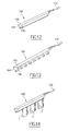
- the figure 12 represents in perspective the clamp 100 of the figure 7 .
- the connection of the clamp 100 to a circuit is performed by an electrical conductor tape 170 (wire, braid, strip, etc.) attached to the rear portion 102 of the clamp 100 (by means of welding, crimping, solder, etc.).
- the figure 13 represents in perspective a clamp 180 whose bearing generator on the anode layers is discontinuous.
- the side portions 184 and 186 of the clamp 180, forming the jaws, are cut into crenellations so as to form teeth. This feature improves the retention of the anode layers in the clamp.
- the figure 14 schematically represents a clamp 100 used for connecting wound coil elements 1, 2, 3 to each other.
- the elements 1, 2 and 3 have their anode connected to the same terminal via the clamp 100 and the conductor 170.
- clamps of the invention can also be used for clamping the cathode collectors of the elements. This feature makes it easy to make serial or parallel connections between elements, as will be shown in the following description.
- the figure 15 represents a double clamp 200 consisting of two elementary clamps connected by their rear portion.
- the double gripper 200 is formed of a simple trapezoidal gripper 100 of the type shown in FIG. figure 7 and a trapezoidal claw gripper 160 of the type shown in FIG. figure 10 .
- the trapezoidal clamp 100 is more particularly suitable for clamping lithium anode layers while the gripper clamp 160 is particularly suitable for clamping collector layers in Bécromal.
- the two elementary clamps 100 and 160 are held together by welding or crimping.
- the double clamp 200 thus formed allows the electrical connection of one or more layers of anode of a battery element to one or more collector layer (s) of another battery element, which allows serialization of these battery cells.
- double tongs can be envisaged. It is possible to produce a double clamp enclosing on one side the protruding parts of one or several layers of anode and on the other side the protruding portions of one or more cathode layer (s). It is also possible to produce a double clamp enclosing on each side the protruding portions of one or more layers of anode. Or two integral clamps enclosing respectively two cathodes.
- the figure 16 is an example of a planar assembly of battery elements 1, 2, 3, 4 in series.
- the elements are arranged head-to-tail flat side by side, parallel to each other, their sides which overflow the layers of lithium anode and collector being alternately oriented in one direction and then in the other.
- the anode of an element is electrically connected to the collector of the next element via a clamp 100.
- the figure 17 is an example of a planar assembly of battery cells 1, 2, 3, 4, 5, 6 in parallel.
- the elements are arranged flat, next to each other, parallel to each other, their sides which overflow the anode and collector layers being oriented in the same direction.
- the anodes of the battery cells are electrically connected to each other by means of the same clamp 100.
- the collectors of the battery cells are electrically connected to each other by means of another clamp 100.
- two elements 1 and 2 or more can be superimposed and connected by the same clamp 100, which allows to connect the two elements in parallel, if the two elements are arranged in the same direction (collector on the same side) or to connect them in parallel if the elements are arranged side by side head to tail.
- the figure 19 schematically represents an example of an assembly in which a double gripper 220 of the type shown in FIG. figure 15 electrically connects a set of elements 1, 2, 3, 4, 5 and 6 arranged flat by their collectors.
- the figure 20 schematically represents an example of parallel assembly.
- a double gripper 220 of the type shown in FIG. figure 15 electrically connects a set of flat-lying battery cells 1, 2, 3, 4, 5 and 6 by their collectors, as on the figure 19 .
- simple tongs 100 of the type shown in FIG. figure 7 electrically connect the elements 1, 2, 3 and 4, 5, 6 by their anodes.
- the clamp 220 is electrically connected to the plus terminal (+) of the battery while the clamps 100 are electrically connected to the minus (-) terminal of the battery.
- the figure 21 schematically represents an example of a mixed serial-parallel plane assembly forming a battery module.
- the clamps 100 and 220 make it possible to achieve flat battery stages whose power and output voltage can be adapted for an identical size of the planar stage, whatever the power and the voltage chosen for the floor.
- clamps 100 and 220 have the additional advantage of stiffening the assembly which can thus be easily manipulated during its assembly in a battery.
Landscapes
- Engineering & Computer Science (AREA)
- Chemical & Material Sciences (AREA)
- Chemical Kinetics & Catalysis (AREA)
- Electrochemistry (AREA)
- General Chemical & Material Sciences (AREA)
- Manufacturing & Machinery (AREA)
- Power Engineering (AREA)
- Microelectronics & Electronic Packaging (AREA)
- Dispersion Chemistry (AREA)
- General Physics & Mathematics (AREA)
- Inorganic Chemistry (AREA)
- Condensed Matter Physics & Semiconductors (AREA)
- Physics & Mathematics (AREA)
- Connection Of Batteries Or Terminals (AREA)
- Battery Mounting, Suspending (AREA)
- Secondary Cells (AREA)
Claims (27)
- Batteriemodul, mindestens ein Element (1, 2, 3, 4) umfassend, das von gemäß einem abgeflachten Profil übereinander gelagerten gewickelten Schichten (10, 20, 30, 40, 50, 60) gebildet wird, wobei bestimmte Schichten (10, 40) Ränder aufweisen, die sich über die Ränder der anderen Schichten (20, 30, 50, 60) erstrecken und somit hervorstehende Abschnitte (12; 42) bilden, und ein Spannorgan (100, 120, 140, 160, 180, 200, 220), das die hervorstehenden Abschnitte (12; 42) bestimmter Schichten (10; 40) gegeneinander gespannt hält, dadurch gekennzeichnet, dass das Spannorgan ein unabhängiges elastisches Organ ist, das durch sich selbst ohne Hilfe von außen das Spannen der hervorstehenden Abschnitte (12; 42) und seinen eigenen Halt auf diesen gewährleistetet und imstande ist, eine elektrische Verbindung der Schichten (10; 40) mit einem Stromkreis zu gewährleisten.
- Modul nach Anspruch 1, dadurch gekennzeichnet, dass das Spannorgan (100, 120, 140, 160, 180, 200, 220) von einer elastischen Zange gebildet wird, die zwei Backen aufweist, die imstande sind, die hervorstehenden Abschnitte (12; 42) der Schichten (10; 40) zu spannen.
- Modul nach Anspruch 2, dadurch gekennzeichnet, dass die Zange aus einer gebogenen Metallplatte geformt ist, um die Spannbacken zu bilden.
- Modul nach Anspruch 3, dadurch gekennzeichnet, dass die freien Enden der Backen gemäß einem Krümmungsradius von über 0,6 mm nach außen gebogen sind.
- Modul nach einem der Ansprüche 2 bis 4, dadurch gekennzeichnet, dass die freien Enden der Backen im Winkel gebogen sind und längliche Langlöcher (221) aufweisen, die imstande sind, die Zähne (229) eines Platzierungswerkzeugs (228, 230) aufzunehmen.
- Modul nach einem der Ansprüche 2 bis 5, dadurch gekennzeichnet, dass die Zange eine maximale Öffnungskraft von 160 N aufweist.
- Modul nach einem der Ansprüche 1 bis 6, dadurch gekennzeichnet, dass das Spannorgan (100, 120, 140, 160, 180, 200, 220) aus Metall ist.
- Modul nach Anspruch 7, dadurch gekennzeichnet, dass das Spannorgan mit einem elektrisch leitenden Element (170) verbunden ist, das imstande ist, die Schichten (10; 40), die vom Spannorgan (100, 120, 140, 160, 180, 200, 220) gespannt gehalten werden, mit einem Stromkreis elektrisch zu verbinden.
- Modul nach einem der vorangehenden Ansprüche, dadurch gekennzeichnet, dass das Spannorgan imstande ist, seinen eigenen Halt auf den hervorstehenden Abschnitten (12; 42) der Schichten (10; 40) zu gewährleisten und eine elektrische Verbindung dieser während einer Dauer über der Lebensdauer des Moduls.
- Modul nach einem der vorangehenden Ansprüche, dadurch gekennzeichnet, dass das Spannorgan (100, 120, 140, 160, 180, 200, 220) auf die hervorstehenden Abschnitte (12; 42) der Schichten (10; 40) eine Spannkraft von über 50 N ausübt.
- Modul nach einem der vorangehenden Ansprüche, dadurch gekennzeichnet, dass das Spannorgan (160) zwei mit Krallen (175, 177) ausgestattete Backen umfasst, die imstande sind, die hervorstehenden Abschnitte (12; 42) der Schichten (10; 40) mechanisch zu ergreifen.
- Modul nach einem der vorangehenden Ansprüche, dadurch gekennzeichnet, dass das Spannorgan (180) zwei Backen umfasst, die Zähne aufweisen.
- Modul nach einem der vorangehenden Ansprüche, dadurch gekennzeichnet, dass das Spannorgan (100, 120, 140, 160, 180, 200, 220) die Schichten mehrerer Elemente gleichzeitig gegeneinander gespannt hält.
- Modul nach einem der vorangehenden Ansprüche, dadurch gekennzeichnet, dass das Spannorgan (100, 120, 140, 160, 180, 200, 220) bimetallisch ist und von einer Platte aus einem Metall mit hohen elastischen Eigenschaften wie Kupfernickel gebildet wird, das verbindend eine Platte aus einem Material mit einer hohen elektrischen Leitfähigkeit wie Neusilber umgibt.
- Modul nach einem der vorangehenden Ansprüche, dadurch gekennzeichnet, dass zwischen dem Spannorgan (100, 120, 140, 160, 180, 200, 220) und den hervorstehenden Abschnitten (12; 42) der Schichten (10; 40) eine Kupferplatte (70) zwischengestellt ist.
- Modul nach einem der vorangehenden Ansprüche, dadurch gekennzeichnet, dass das Spannorgan (100) auf Ebene eines länglichen Endes längliche Schlitze (101, 103) aufweist, das Schutzlaschen (112, 114, 116) ohne Spannung für die vom Spannorgan gespannten Schichten definiert.
- Modul nach einem der vorangehenden Ansprüche, dadurch gekennzeichnet, dass das Spannorgan auf einem äußeren Abschnitt (102, 104, 106) einen elektrisch isolierenden Überzug aufweist, der imstande ist, Kurzschlüsse mit einem benachbarten Element zu verhindern.
- Modul nach einem der vorangehenden Ansprüche, dadurch gekennzeichnet, dass das Spannorgan (100, 120, 140, 160, 180, 200, 220) eine elastische Zange aufweist, die die hervorstehenden Abschnitte einer oder mehrerer Anodenschicht(en) spannt.
- Modul nach einem der vorangehenden Ansprüche, dadurch gekennzeichnet, dass das Spannorgan (100, 120, 140, 160, 180, 200, 220) eine elastische Zange aufweist, die die hervorstehenden Abschnitte einer oder mehrerer Kollektorschicht(en) spannt.
- Modul nach einem der vorangehenden Ansprüche, dadurch gekennzeichnet, dass das Spannorgan (100, 120, 140, 160, 180, 200, 220) eine Doppelzange aufweist, die auf einer Seite die hervorstehenden Abschnitte einer oder mehrerer Anodenschicht(en) eines ersten Elements und auf der anderen Seite die hervorstehenden Abschnitte einer oder mehrerer Kollektorschicht(en) (10) eines zweiten Elements spannt, wodurch die zwei Elemente dann elektrisch in Reihe verbunden sind.
- Modul nach einem der vorangehenden Ansprüche, dadurch gekennzeichnet, dass das Spannorgan (100, 120, 140, 160, 180, 200, 220) eine Doppelzange aufweist, die auf jeder Seite die hervorstehenden Abschnitte einer oder mehrerer Anodenschicht(en) zweier benachbarter Elemente spannt, um sie elektrisch parallel zu verbinden.
- Modul nach einem der vorangehenden Ansprüche, dadurch gekennzeichnet, dass das Spannorgan (100, 120, 140, 160, 180, 200, 220) zwei verbundene Zangen umfasst, die jeweils die Kollektoren von zwei Elementen spannt, um diese Elemente elektrisch parallel zu verbinden.
- Modul nach einem der vorangehenden Ansprüche, dadurch gekennzeichnet, dass das Spannorgan ein elastisches Organ ist, das eine Spannung der hervorstehenden Abschnitte (12; 42) mit konstanter Kraft gewährleistet, unabhängig von den Unterschieden bei der Herstellung der Elemente.
- Modul nach einem der vorangehenden Ansprüche, dadurch gekennzeichnet, dass das Spannorgan einen Anlegewinkel auf den hervorstehenden Abschnitten (12; 42) der Schichten (10; 40) zwischen 10° und 30° inklusive aufweist.
- Verfahren zur Herstellung einer elektrischen Verbindung auf einem Batteriemodul, mindestens ein Element (1, 2, 3, 4) umfassend, das von gemäß einem abgeflachten Profil übereinander gelagerten gewickelten Schichten (10, 20, 30, 40, 50, 60) gebildet wird, wobei bestimmte Schichten (10, 40) Ränder aufweisen, die sich über die Ränder der anderen Schichten (20, 30, 50, 60) erstrecken und somit hervorstehende Abschnitte (12; 42) bilden, wobei das Verfahren die Platzierung eines Spannorgans (100, 120, 140, 160, 180, 200, 220) umfasst, das die hervorstehenden Abschnitte (12; 42) bestimmter Schichten (10; 40) gegeneinander gespannt hält, wobei das Spannorgan ein unabhängiges elastisches Organ ist, das durch sich selbst ohne Hilfe von außen das Spannen der hervorstehenden Abschnitte und seinen eigenen Halt auf diesen gewährleistetet und imstande ist, eine elektrische Verbindung der Schichten mit einem Stromkreis zu gewährleisten.
- Verfahren nach Anspruch 25, dadurch gekennzeichnet, dass das Spannorgan (100, 120, 140, 160, 180, 200, 220) von einer elastischen Zange gebildet wird, die zwei Backen aufweist, die imstande sind, die hervorstehenden Abschnitte (12; 42) der Schichten (10; 40) zu spannen, wobei das Verfahren die folgenden Schritte umfasst, die bestehen in:- Spreizen der Backen der elastischen Zange mit Hilfe eines aus zwei Elementen (108, 110) gebildeten Werkzeugs, wobei jedes Element (108, 110) imstande ist, in einen Haken (125, 127) oder Öffnungen (221) einer der Backen (104, 106; 124, 126; 144, 146; 164, 166; 224, 226) einzugreifen,- danach Führen der hervorstehenden Abschnitte (12; 42) der Schichten (10; 40) zwischen die Backen (104, 106; 124, 126; 144, 146; 164, 166; 224, 226),- Loslassen der Backen (104, 106; 124, 126; 144, 146; 164, 166; 224, 226) derart, dass sie die hervorstehenden Abschnitte (12; 42) spannen.
- Verfahren nach Anspruch 26, dadurch gekennzeichnet, dass das Werkzeug einen Anschlag (223) aufweist, der das Spreizen der Backen der Zange über die elastische Grenze des Materials hinaus, das sie bildet, verhindert.
Priority Applications (1)
| Application Number | Priority Date | Filing Date | Title |
|---|---|---|---|
| PL05801393T PL1810355T3 (pl) | 2004-10-06 | 2005-10-05 | Moduł baterii zawierający element magazynujący energię, którego styk jest wykonany przez ściskanie warstw ze sobą |
Applications Claiming Priority (2)
| Application Number | Priority Date | Filing Date | Title |
|---|---|---|---|
| FR0410522A FR2876221B1 (fr) | 2004-10-06 | 2004-10-06 | Module de batterie comprenant un element de stockage d'energie dont le contact est realise par serrage des couches entre elles |
| PCT/EP2005/055018 WO2006037790A2 (fr) | 2004-10-06 | 2005-10-05 | Module de batterie comprenant un element de stockage d'energie dont le contact est realise par serrage des couches entre elles |
Publications (2)
| Publication Number | Publication Date |
|---|---|
| EP1810355A2 EP1810355A2 (de) | 2007-07-25 |
| EP1810355B1 true EP1810355B1 (de) | 2008-08-20 |
Family
ID=34949451
Family Applications (1)
| Application Number | Title | Priority Date | Filing Date |
|---|---|---|---|
| EP05801393A Expired - Lifetime EP1810355B1 (de) | 2004-10-06 | 2005-10-05 | Batteriemodul mit einem energiespeicherelement, bei dem der kontakt durch gegenseitige schichtanspannung aktiviert wird |
Country Status (10)
| Country | Link |
|---|---|
| US (1) | US20090104518A1 (de) |
| EP (1) | EP1810355B1 (de) |
| JP (1) | JP4828541B2 (de) |
| KR (1) | KR101313300B1 (de) |
| AT (1) | ATE405958T1 (de) |
| CA (1) | CA2582030C (de) |
| DE (1) | DE602005009241D1 (de) |
| FR (1) | FR2876221B1 (de) |
| PL (1) | PL1810355T3 (de) |
| WO (1) | WO2006037790A2 (de) |
Cited By (1)
| Publication number | Priority date | Publication date | Assignee | Title |
|---|---|---|---|---|
| TWI396318B (zh) * | 2010-04-19 | 2013-05-11 | Simplo Technology Co Ltd | 電池模組 |
Families Citing this family (19)
| Publication number | Priority date | Publication date | Assignee | Title |
|---|---|---|---|---|
| JP5559279B2 (ja) * | 2006-08-11 | 2014-07-23 | 三洋電機株式会社 | 二次電池 |
| JP4491747B2 (ja) | 2007-07-23 | 2010-06-30 | トヨタ自動車株式会社 | 電池 |
| US20090159354A1 (en) * | 2007-12-25 | 2009-06-25 | Wenfeng Jiang | Battery system having interconnected battery packs each having multiple electrochemical storage cells |
| US8399116B2 (en) | 2007-12-25 | 2013-03-19 | Byd Co. Ltd. | Optimized dimensional relationships for an electrochemical cell having a coiled core |
| US7563137B1 (en) * | 2008-06-30 | 2009-07-21 | Lg Chem, Ltd. | Mechanical fastener for coupling to electrical terminals of battery modules and method for coupling to electrical terminals |
| TW201101559A (en) | 2009-06-17 | 2011-01-01 | Gs Yuasa Int Ltd | Battery and its production method |
| KR101122811B1 (ko) * | 2010-06-17 | 2012-03-21 | 삼성에스디아이 주식회사 | 이차전지의 전극탭 연결구조 및 이를 이용한 이차전지 |
| KR101446161B1 (ko) * | 2011-08-17 | 2014-10-01 | 주식회사 엘지화학 | 캡 조립체 및 이를 이용한 이차 전지 |
| JP5803713B2 (ja) * | 2012-02-08 | 2015-11-04 | 株式会社豊田自動織機 | 蓄電装置及び車両 |
| US10734655B2 (en) | 2012-05-10 | 2020-08-04 | Gs Yuasa International Ltd. | Electric storage device |
| FR3008549B1 (fr) * | 2013-07-11 | 2015-06-26 | Renault Sa | Module a plusieurs cellules demontables, batterie comportant un tel module et vehicule comportant une telle batterie |
| JP6857294B2 (ja) * | 2016-02-29 | 2021-04-14 | 株式会社Gsユアサ | 蓄電素子及び蓄電素子の製造方法 |
| CN106601947A (zh) * | 2016-11-23 | 2017-04-26 | 深圳市沃特玛电池有限公司 | 一种电池组件 |
| KR102268336B1 (ko) * | 2017-01-06 | 2021-06-23 | 주식회사 엘지에너지솔루션 | 냉각 효율성이 향상된 전지셀 |
| KR102681497B1 (ko) * | 2017-02-07 | 2024-07-04 | 에이치그린파워 주식회사 | 배터리 모듈 및 배터리 모듈용 센싱 유닛 |
| DE102018112313A1 (de) * | 2018-05-23 | 2019-11-28 | Auto-Kabel Management Gmbh | Batteriezellenverbinder |
| JP7343419B2 (ja) * | 2020-02-14 | 2023-09-12 | 本田技研工業株式会社 | 固体電池セル及び固体電池モジュール |
| JP7686409B2 (ja) * | 2021-02-25 | 2025-06-02 | 株式会社東芝 | 電池 |
| JP2025511613A (ja) * | 2022-10-21 | 2025-04-16 | エルジー エナジー ソリューション リミテッド | 電極アセンブリの製造方法 |
Family Cites Families (15)
| Publication number | Priority date | Publication date | Assignee | Title |
|---|---|---|---|---|
| CA1240363A (en) * | 1983-10-28 | 1988-08-09 | John E. Keem | Electrodes made with disordered active material and method of making the same |
| GB8510152D0 (en) * | 1985-04-20 | 1985-05-30 | Lucas Ind Plc | Alakaline electric storage cells |
| US4610187A (en) * | 1985-11-22 | 1986-09-09 | Wittek Industries, Inc. | Tool for applying and removing a spring clamp |
| JPH05198294A (ja) * | 1992-01-17 | 1993-08-06 | Sony Corp | 端子板及びこれを用いた電池収納ケース |
| CA2068290C (fr) * | 1992-05-08 | 1999-07-13 | Michel Gauthier | Prise de contact electrique sur des anodes de lithium |
| US5487958A (en) * | 1993-12-06 | 1996-01-30 | Tura; Drew | Interlocking frame system for lithium-polymer battery construction |
| FR2737339B1 (fr) * | 1995-07-28 | 1997-10-17 | Bollore Technologies | Condensateur a dielectrique en polypropylene et film metallise pour la realisation d'un tel condensateur |
| FR2759087B1 (fr) * | 1997-02-06 | 1999-07-30 | Electricite De France | Produit composite poreux de haute surface specifique, procede de preparation et electrode pour ensemble electrochimique formee d'un film composite poreux |
| JP2000150306A (ja) * | 1998-11-12 | 2000-05-30 | Toyota Motor Corp | 電池またはキャパシタの集電方式 |
| FI110476B (fi) * | 1999-06-02 | 2003-02-14 | Tanja Niemivuo | Tarjoilijan apulaite |
| JP4162175B2 (ja) * | 1999-09-08 | 2008-10-08 | 日立マクセル株式会社 | ポリマー電解質電池 |
| FR2808622B1 (fr) * | 2000-05-04 | 2006-09-08 | Bollore | Generateur electrochimique a electrolyte polymerique comprenant des polymeres fluores |
| US6849358B2 (en) * | 2001-04-06 | 2005-02-01 | Ngk Spark Plug Co., Ltd. | Lithium ion battery |
| CA2384215A1 (en) * | 2002-04-30 | 2003-10-30 | Richard Laliberte | Electrochemical bundle and method for making same |
| AU2003302288A1 (en) * | 2002-11-27 | 2004-06-18 | Mitsui Mining And Smelting Co., Ltd. | Negative electrode collector for nonaqueous electrolyte secondary battery and method for manufacturing same |
-
2004
- 2004-10-06 FR FR0410522A patent/FR2876221B1/fr not_active Expired - Fee Related
-
2005
- 2005-10-05 US US11/664,927 patent/US20090104518A1/en not_active Abandoned
- 2005-10-05 KR KR1020077010391A patent/KR101313300B1/ko not_active Expired - Fee Related
- 2005-10-05 WO PCT/EP2005/055018 patent/WO2006037790A2/fr not_active Ceased
- 2005-10-05 PL PL05801393T patent/PL1810355T3/pl unknown
- 2005-10-05 EP EP05801393A patent/EP1810355B1/de not_active Expired - Lifetime
- 2005-10-05 JP JP2007535164A patent/JP4828541B2/ja not_active Expired - Fee Related
- 2005-10-05 DE DE602005009241T patent/DE602005009241D1/de not_active Expired - Lifetime
- 2005-10-05 CA CA2582030A patent/CA2582030C/fr not_active Expired - Fee Related
- 2005-10-05 AT AT05801393T patent/ATE405958T1/de not_active IP Right Cessation
Cited By (1)
| Publication number | Priority date | Publication date | Assignee | Title |
|---|---|---|---|---|
| TWI396318B (zh) * | 2010-04-19 | 2013-05-11 | Simplo Technology Co Ltd | 電池模組 |
Also Published As
| Publication number | Publication date |
|---|---|
| PL1810355T3 (pl) | 2009-01-30 |
| CA2582030A1 (fr) | 2006-04-13 |
| JP4828541B2 (ja) | 2011-11-30 |
| WO2006037790A3 (fr) | 2007-04-12 |
| FR2876221B1 (fr) | 2006-12-22 |
| KR101313300B1 (ko) | 2013-09-30 |
| JP2008516383A (ja) | 2008-05-15 |
| CA2582030C (fr) | 2013-12-24 |
| DE602005009241D1 (de) | 2008-10-02 |
| ATE405958T1 (de) | 2008-09-15 |
| US20090104518A1 (en) | 2009-04-23 |
| KR20070098790A (ko) | 2007-10-05 |
| EP1810355A2 (de) | 2007-07-25 |
| FR2876221A1 (fr) | 2006-04-07 |
| WO2006037790A2 (fr) | 2006-04-13 |
Similar Documents
| Publication | Publication Date | Title |
|---|---|---|
| CA2582030C (fr) | Module de batterie comprenant un element de stockage d'energie dont le contact est realise par serrage des couches entre elles | |
| US8530084B2 (en) | Electrode structure for non-aqueous electrolyte secondary battery, method for producing the same, and non-aqueous electrolyte secondary battery | |
| EP1961058B1 (de) | Elektrochemische batterie und herstellungsverfahren dafür | |
| EP0822605B1 (de) | Zylindrischer elektrochemischer Generator mit spiralförmig gewickelten Elektroden | |
| CA2384215A1 (en) | Electrochemical bundle and method for making same | |
| EP2133942A1 (de) | Sekundärbatterie und verfahren zum herstellen einer sekundärbatterie | |
| EP2093820B1 (de) | Elektrische Verbindung für Stromakkumulator | |
| FR2787925A1 (fr) | Generateur electrochimique dans lequel une electrode a un bord renforce par un feuillard | |
| JP4690013B2 (ja) | 接続装置およびそれを用いた電気デバイス集合体 | |
| FR3039005A1 (fr) | Batterie en couches minces autosupportee et procede de fabrication d'une telle batterie | |
| FR3125172A1 (fr) | Pièce de connexion pour élément électrochimique de format prismatique | |
| CN115053393B (zh) | 蓄电模块 | |
| CH716259A2 (fr) | Batterie cellulaire. | |
| US11826861B1 (en) | Joining systems, clamping fixtures, and related systems and methods | |
| CH716260A2 (fr) | Batterie cellulaire. | |
| EP3114726B1 (de) | Anordnungsmodul mit elektrochemischen, von laschen und verbindungsclips aufgenommenen zellen | |
| EP2239802A1 (de) | Batterie und Hestellungsverfahren | |
| EP4342018A1 (de) | Elektrochemisches element für eine batterie und entsprechende batterie | |
| FR2894718A1 (fr) | Module de batterie | |
| CN100405656C (zh) | 棱柱形电池单元,具棱柱形电池单元的电池及其制造方法 | |
| EP2750228A1 (de) | Steckverbinder für Brennstoffzellen, und entsprechendes Umsetzungsverfahren | |
| WO2023118077A1 (fr) | Faisceau électrochimique, élément de batterie et procédés de fabrication associés | |
| EP4645489A1 (de) | Elektrochemisches element mit spiralförmig gewickeltem elektrochemischem strahl und verfahren zu seiner herstellung | |
| KR20260014202A (ko) | 이차 전지 및 이차 전지 제조 방법 | |
| FR2789229A1 (fr) | Electrode spiralee a support tridimensionnel |
Legal Events
| Date | Code | Title | Description |
|---|---|---|---|
| PUAI | Public reference made under article 153(3) epc to a published international application that has entered the european phase |
Free format text: ORIGINAL CODE: 0009012 |
|
| 17P | Request for examination filed |
Effective date: 20070507 |
|
| AK | Designated contracting states |
Kind code of ref document: A2 Designated state(s): AT BE BG CH CY CZ DE DK EE ES FI FR GB GR HU IE IS IT LI LT LU LV MC NL PL PT RO SE SI SK TR |
|
| AX | Request for extension of the european patent |
Extension state: AL BA HR MK YU |
|
| DAX | Request for extension of the european patent (deleted) | ||
| GRAP | Despatch of communication of intention to grant a patent |
Free format text: ORIGINAL CODE: EPIDOSNIGR1 |
|
| RIC1 | Information provided on ipc code assigned before grant |
Ipc: H01M 10/04 20060101ALI20080226BHEP Ipc: H01M 2/26 20060101ALI20080226BHEP Ipc: H01M 2/22 20060101AFI20080226BHEP |
|
| GRAS | Grant fee paid |
Free format text: ORIGINAL CODE: EPIDOSNIGR3 |
|
| GRAA | (expected) grant |
Free format text: ORIGINAL CODE: 0009210 |
|
| AK | Designated contracting states |
Kind code of ref document: B1 Designated state(s): AT BE BG CH CY CZ DE DK EE ES FI FR GB GR HU IE IS IT LI LT LU LV MC NL PL PT RO SE SI SK TR |
|
| REG | Reference to a national code |
Ref country code: GB Ref legal event code: FG4D Free format text: NOT ENGLISH |
|
| REG | Reference to a national code |
Ref country code: CH Ref legal event code: EP |
|
| REG | Reference to a national code |
Ref country code: IE Ref legal event code: FG4D Free format text: LANGUAGE OF EP DOCUMENT: FRENCH |
|
| REF | Corresponds to: |
Ref document number: 602005009241 Country of ref document: DE Date of ref document: 20081002 Kind code of ref document: P |
|
| REG | Reference to a national code |
Ref country code: RO Ref legal event code: EPE |
|
| REG | Reference to a national code |
Ref country code: CH Ref legal event code: NV Representative=s name: MICHELI & CIE SA |
|
| PG25 | Lapsed in a contracting state [announced via postgrant information from national office to epo] |
Ref country code: IS Free format text: LAPSE BECAUSE OF FAILURE TO SUBMIT A TRANSLATION OF THE DESCRIPTION OR TO PAY THE FEE WITHIN THE PRESCRIBED TIME-LIMIT Effective date: 20081220 Ref country code: NL Free format text: LAPSE BECAUSE OF FAILURE TO SUBMIT A TRANSLATION OF THE DESCRIPTION OR TO PAY THE FEE WITHIN THE PRESCRIBED TIME-LIMIT Effective date: 20080820 Ref country code: LT Free format text: LAPSE BECAUSE OF FAILURE TO SUBMIT A TRANSLATION OF THE DESCRIPTION OR TO PAY THE FEE WITHIN THE PRESCRIBED TIME-LIMIT Effective date: 20080820 |
|
| REG | Reference to a national code |
Ref country code: PL Ref legal event code: T3 |
|
| PG25 | Lapsed in a contracting state [announced via postgrant information from national office to epo] |
Ref country code: SI Free format text: LAPSE BECAUSE OF FAILURE TO SUBMIT A TRANSLATION OF THE DESCRIPTION OR TO PAY THE FEE WITHIN THE PRESCRIBED TIME-LIMIT Effective date: 20080820 Ref country code: AT Free format text: LAPSE BECAUSE OF FAILURE TO SUBMIT A TRANSLATION OF THE DESCRIPTION OR TO PAY THE FEE WITHIN THE PRESCRIBED TIME-LIMIT Effective date: 20080820 Ref country code: ES Free format text: LAPSE BECAUSE OF FAILURE TO SUBMIT A TRANSLATION OF THE DESCRIPTION OR TO PAY THE FEE WITHIN THE PRESCRIBED TIME-LIMIT Effective date: 20081201 Ref country code: FI Free format text: LAPSE BECAUSE OF FAILURE TO SUBMIT A TRANSLATION OF THE DESCRIPTION OR TO PAY THE FEE WITHIN THE PRESCRIBED TIME-LIMIT Effective date: 20080820 Ref country code: LV Free format text: LAPSE BECAUSE OF FAILURE TO SUBMIT A TRANSLATION OF THE DESCRIPTION OR TO PAY THE FEE WITHIN THE PRESCRIBED TIME-LIMIT Effective date: 20080820 |
|
| BERE | Be: lapsed |
Owner name: BATSCAP Effective date: 20081031 |
|
| PG25 | Lapsed in a contracting state [announced via postgrant information from national office to epo] |
Ref country code: BG Free format text: LAPSE BECAUSE OF FAILURE TO SUBMIT A TRANSLATION OF THE DESCRIPTION OR TO PAY THE FEE WITHIN THE PRESCRIBED TIME-LIMIT Effective date: 20081120 Ref country code: DK Free format text: LAPSE BECAUSE OF FAILURE TO SUBMIT A TRANSLATION OF THE DESCRIPTION OR TO PAY THE FEE WITHIN THE PRESCRIBED TIME-LIMIT Effective date: 20080820 |
|
| PG25 | Lapsed in a contracting state [announced via postgrant information from national office to epo] |
Ref country code: SK Free format text: LAPSE BECAUSE OF FAILURE TO SUBMIT A TRANSLATION OF THE DESCRIPTION OR TO PAY THE FEE WITHIN THE PRESCRIBED TIME-LIMIT Effective date: 20080820 Ref country code: MC Free format text: LAPSE BECAUSE OF NON-PAYMENT OF DUE FEES Effective date: 20081031 |
|
| PLBE | No opposition filed within time limit |
Free format text: ORIGINAL CODE: 0009261 |
|
| STAA | Information on the status of an ep patent application or granted ep patent |
Free format text: STATUS: NO OPPOSITION FILED WITHIN TIME LIMIT |
|
| REG | Reference to a national code |
Ref country code: HU Ref legal event code: AG4A Ref document number: E005026 Country of ref document: HU |
|
| 26N | No opposition filed |
Effective date: 20090525 |
|
| PG25 | Lapsed in a contracting state [announced via postgrant information from national office to epo] |
Ref country code: EE Free format text: LAPSE BECAUSE OF FAILURE TO SUBMIT A TRANSLATION OF THE DESCRIPTION OR TO PAY THE FEE WITHIN THE PRESCRIBED TIME-LIMIT Effective date: 20080820 |
|
| PG25 | Lapsed in a contracting state [announced via postgrant information from national office to epo] |
Ref country code: BE Free format text: LAPSE BECAUSE OF NON-PAYMENT OF DUE FEES Effective date: 20081031 |
|
| PG25 | Lapsed in a contracting state [announced via postgrant information from national office to epo] |
Ref country code: SE Free format text: LAPSE BECAUSE OF FAILURE TO SUBMIT A TRANSLATION OF THE DESCRIPTION OR TO PAY THE FEE WITHIN THE PRESCRIBED TIME-LIMIT Effective date: 20081120 |
|
| PG25 | Lapsed in a contracting state [announced via postgrant information from national office to epo] |
Ref country code: CY Free format text: LAPSE BECAUSE OF FAILURE TO SUBMIT A TRANSLATION OF THE DESCRIPTION OR TO PAY THE FEE WITHIN THE PRESCRIBED TIME-LIMIT Effective date: 20080820 Ref country code: LU Free format text: LAPSE BECAUSE OF NON-PAYMENT OF DUE FEES Effective date: 20081005 |
|
| PG25 | Lapsed in a contracting state [announced via postgrant information from national office to epo] |
Ref country code: TR Free format text: LAPSE BECAUSE OF FAILURE TO SUBMIT A TRANSLATION OF THE DESCRIPTION OR TO PAY THE FEE WITHIN THE PRESCRIBED TIME-LIMIT Effective date: 20080820 |
|
| PG25 | Lapsed in a contracting state [announced via postgrant information from national office to epo] |
Ref country code: GR Free format text: LAPSE BECAUSE OF FAILURE TO SUBMIT A TRANSLATION OF THE DESCRIPTION OR TO PAY THE FEE WITHIN THE PRESCRIBED TIME-LIMIT Effective date: 20081121 |
|
| PG25 | Lapsed in a contracting state [announced via postgrant information from national office to epo] |
Ref country code: PT Free format text: LAPSE BECAUSE OF FAILURE TO SUBMIT A TRANSLATION OF THE DESCRIPTION OR TO PAY THE FEE WITHIN THE PRESCRIBED TIME-LIMIT Effective date: 20080820 |
|
| REG | Reference to a national code |
Ref country code: FR Ref legal event code: CD Owner name: BLUE SOLUTIONS, FR Effective date: 20131001 |
|
| REG | Reference to a national code |
Ref country code: CH Ref legal event code: PFA Owner name: BLUE SOLUTIONS, FR Free format text: FORMER OWNER: BATSCAP, FR |
|
| REG | Reference to a national code |
Ref country code: HU Ref legal event code: HC9C Owner name: BLUE SOLUTIONS, FR Free format text: FORMER OWNER(S): BATSCAP, FR |
|
| REG | Reference to a national code |
Ref country code: DE Ref legal event code: R082 Ref document number: 602005009241 Country of ref document: DE Representative=s name: SAMSON & PARTNER, PATENTANWAELTE, DE |
|
| REG | Reference to a national code |
Ref country code: DE Ref legal event code: R082 Ref document number: 602005009241 Country of ref document: DE Representative=s name: SAMSON & PARTNER, PATENTANWAELTE, DE Effective date: 20140902 Ref country code: DE Ref legal event code: R081 Ref document number: 602005009241 Country of ref document: DE Owner name: BLUE SOLUTIONS, FR Free format text: FORMER OWNER: BATSCAP, ERGUE-GABERIC, FR Effective date: 20140902 Ref country code: DE Ref legal event code: R082 Ref document number: 602005009241 Country of ref document: DE Representative=s name: SAMSON & PARTNER PATENTANWAELTE MBB, DE Effective date: 20140902 |
|
| REG | Reference to a national code |
Ref country code: FR Ref legal event code: PLFP Year of fee payment: 11 |
|
| REG | Reference to a national code |
Ref country code: FR Ref legal event code: PLFP Year of fee payment: 12 |
|
| REG | Reference to a national code |
Ref country code: FR Ref legal event code: PLFP Year of fee payment: 13 |
|
| REG | Reference to a national code |
Ref country code: FR Ref legal event code: PLFP Year of fee payment: 14 |
|
| PGFP | Annual fee paid to national office [announced via postgrant information from national office to epo] |
Ref country code: IE Payment date: 20180918 Year of fee payment: 14 |
|
| PGFP | Annual fee paid to national office [announced via postgrant information from national office to epo] |
Ref country code: PL Payment date: 20180914 Year of fee payment: 14 Ref country code: CZ Payment date: 20180918 Year of fee payment: 14 |
|
| PGFP | Annual fee paid to national office [announced via postgrant information from national office to epo] |
Ref country code: RO Payment date: 20181002 Year of fee payment: 14 |
|
| PGFP | Annual fee paid to national office [announced via postgrant information from national office to epo] |
Ref country code: CH Payment date: 20181022 Year of fee payment: 14 |
|
| PG25 | Lapsed in a contracting state [announced via postgrant information from national office to epo] |
Ref country code: CZ Free format text: LAPSE BECAUSE OF NON-PAYMENT OF DUE FEES Effective date: 20191005 |
|
| REG | Reference to a national code |
Ref country code: CH Ref legal event code: PL |
|
| PG25 | Lapsed in a contracting state [announced via postgrant information from national office to epo] |
Ref country code: CH Free format text: LAPSE BECAUSE OF NON-PAYMENT OF DUE FEES Effective date: 20191031 Ref country code: LI Free format text: LAPSE BECAUSE OF NON-PAYMENT OF DUE FEES Effective date: 20191031 Ref country code: RO Free format text: LAPSE BECAUSE OF NON-PAYMENT OF DUE FEES Effective date: 20191005 |
|
| PG25 | Lapsed in a contracting state [announced via postgrant information from national office to epo] |
Ref country code: HU Free format text: LAPSE BECAUSE OF NON-PAYMENT OF DUE FEES Effective date: 20191006 |
|
| PG25 | Lapsed in a contracting state [announced via postgrant information from national office to epo] |
Ref country code: IT Free format text: LAPSE BECAUSE OF NON-PAYMENT OF DUE FEES Effective date: 20191005 Ref country code: IE Free format text: LAPSE BECAUSE OF NON-PAYMENT OF DUE FEES Effective date: 20191005 |
|
| REG | Reference to a national code |
Ref country code: DE Ref legal event code: R079 Ref document number: 602005009241 Country of ref document: DE Free format text: PREVIOUS MAIN CLASS: H01M0002220000 Ipc: H01M0050528000 |
|
| PG25 | Lapsed in a contracting state [announced via postgrant information from national office to epo] |
Ref country code: PL Free format text: LAPSE BECAUSE OF NON-PAYMENT OF DUE FEES Effective date: 20191005 |
|
| PGFP | Annual fee paid to national office [announced via postgrant information from national office to epo] |
Ref country code: GB Payment date: 20220921 Year of fee payment: 18 |
|
| PGFP | Annual fee paid to national office [announced via postgrant information from national office to epo] |
Ref country code: DE Payment date: 20220920 Year of fee payment: 18 |
|
| REG | Reference to a national code |
Ref country code: DE Ref legal event code: R119 Ref document number: 602005009241 Country of ref document: DE |
|
| GBPC | Gb: european patent ceased through non-payment of renewal fee |
Effective date: 20231005 |
|
| PG25 | Lapsed in a contracting state [announced via postgrant information from national office to epo] |
Ref country code: GB Free format text: LAPSE BECAUSE OF NON-PAYMENT OF DUE FEES Effective date: 20231005 |
|
| PG25 | Lapsed in a contracting state [announced via postgrant information from national office to epo] |
Ref country code: GB Free format text: LAPSE BECAUSE OF NON-PAYMENT OF DUE FEES Effective date: 20231005 Ref country code: DE Free format text: LAPSE BECAUSE OF NON-PAYMENT OF DUE FEES Effective date: 20240501 |
|
| PGFP | Annual fee paid to national office [announced via postgrant information from national office to epo] |
Ref country code: FR Payment date: 20240919 Year of fee payment: 20 |