EP1810863A1 - Orifice comprenant un séparateur de membrane - Google Patents
Orifice comprenant un séparateur de membrane Download PDFInfo
- Publication number
- EP1810863A1 EP1810863A1 EP20070250227 EP07250227A EP1810863A1 EP 1810863 A1 EP1810863 A1 EP 1810863A1 EP 20070250227 EP20070250227 EP 20070250227 EP 07250227 A EP07250227 A EP 07250227A EP 1810863 A1 EP1810863 A1 EP 1810863A1
- Authority
- EP
- European Patent Office
- Prior art keywords
- fuel
- vent
- cap
- separator membrane
- membrane
- Prior art date
- Legal status (The legal status is an assumption and is not a legal conclusion. Google has not performed a legal analysis and makes no representation as to the accuracy of the status listed.)
- Withdrawn
Links
Images


Classifications
-
- B—PERFORMING OPERATIONS; TRANSPORTING
- B60—VEHICLES IN GENERAL
- B60K—ARRANGEMENT OR MOUNTING OF PROPULSION UNITS OR OF TRANSMISSIONS IN VEHICLES; ARRANGEMENT OR MOUNTING OF PLURAL DIVERSE PRIME-MOVERS IN VEHICLES; AUXILIARY DRIVES FOR VEHICLES; INSTRUMENTATION OR DASHBOARDS FOR VEHICLES; ARRANGEMENTS IN CONNECTION WITH COOLING, AIR INTAKE, GAS EXHAUST OR FUEL SUPPLY OF PROPULSION UNITS IN VEHICLES
- B60K15/00—Arrangement in connection with fuel supply of combustion engines or other fuel consuming energy converters, e.g. fuel cells; Mounting or construction of fuel tanks
- B60K15/03—Fuel tanks
- B60K15/04—Tank inlets
- B60K15/0406—Filler caps for fuel tanks
- B60K15/0409—Provided with a lock
-
- F—MECHANICAL ENGINEERING; LIGHTING; HEATING; WEAPONS; BLASTING
- F16—ENGINEERING ELEMENTS AND UNITS; GENERAL MEASURES FOR PRODUCING AND MAINTAINING EFFECTIVE FUNCTIONING OF MACHINES OR INSTALLATIONS; THERMAL INSULATION IN GENERAL
- F16K—VALVES; TAPS; COCKS; ACTUATING-FLOATS; DEVICES FOR VENTING OR AERATING
- F16K24/00—Devices, e.g. valves, for venting or aerating enclosures
- F16K24/04—Devices, e.g. valves, for venting or aerating enclosures for venting only
-
- Y—GENERAL TAGGING OF NEW TECHNOLOGICAL DEVELOPMENTS; GENERAL TAGGING OF CROSS-SECTIONAL TECHNOLOGIES SPANNING OVER SEVERAL SECTIONS OF THE IPC; TECHNICAL SUBJECTS COVERED BY FORMER USPC CROSS-REFERENCE ART COLLECTIONS [XRACs] AND DIGESTS
- Y10—TECHNICAL SUBJECTS COVERED BY FORMER USPC
- Y10T—TECHNICAL SUBJECTS COVERED BY FORMER US CLASSIFICATION
- Y10T137/00—Fluid handling
- Y10T137/2931—Diverse fluid containing pressure systems
- Y10T137/3003—Fluid separating traps or vents
- Y10T137/3084—Discriminating outlet for gas
- Y10T137/309—Fluid sensing valve
- Y10T137/3099—Float responsive
-
- Y—GENERAL TAGGING OF NEW TECHNOLOGICAL DEVELOPMENTS; GENERAL TAGGING OF CROSS-SECTIONAL TECHNOLOGIES SPANNING OVER SEVERAL SECTIONS OF THE IPC; TECHNICAL SUBJECTS COVERED BY FORMER USPC CROSS-REFERENCE ART COLLECTIONS [XRACs] AND DIGESTS
- Y10—TECHNICAL SUBJECTS COVERED BY FORMER USPC
- Y10T—TECHNICAL SUBJECTS COVERED BY FORMER US CLASSIFICATION
- Y10T137/00—Fluid handling
- Y10T137/8593—Systems
- Y10T137/86292—System with plural openings, one a gas vent or access opening
- Y10T137/86324—Tank with gas vent and inlet or outlet
- Y10T137/86332—Vent and inlet or outlet in unitary mounting
-
- Y—GENERAL TAGGING OF NEW TECHNOLOGICAL DEVELOPMENTS; GENERAL TAGGING OF CROSS-SECTIONAL TECHNOLOGIES SPANNING OVER SEVERAL SECTIONS OF THE IPC; TECHNICAL SUBJECTS COVERED BY FORMER USPC CROSS-REFERENCE ART COLLECTIONS [XRACs] AND DIGESTS
- Y10—TECHNICAL SUBJECTS COVERED BY FORMER USPC
- Y10T—TECHNICAL SUBJECTS COVERED BY FORMER US CLASSIFICATION
- Y10T29/00—Metal working
- Y10T29/49—Method of mechanical manufacture
- Y10T29/49826—Assembling or joining
- Y10T29/49863—Assembling or joining with prestressing of part
- Y10T29/49876—Assembling or joining with prestressing of part by snap fit
-
- Y—GENERAL TAGGING OF NEW TECHNOLOGICAL DEVELOPMENTS; GENERAL TAGGING OF CROSS-SECTIONAL TECHNOLOGIES SPANNING OVER SEVERAL SECTIONS OF THE IPC; TECHNICAL SUBJECTS COVERED BY FORMER USPC CROSS-REFERENCE ART COLLECTIONS [XRACs] AND DIGESTS
- Y10—TECHNICAL SUBJECTS COVERED BY FORMER USPC
- Y10T—TECHNICAL SUBJECTS COVERED BY FORMER US CLASSIFICATION
- Y10T29/00—Metal working
- Y10T29/49—Method of mechanical manufacture
- Y10T29/49826—Assembling or joining
- Y10T29/49904—Assembling a subassembly, then assembling with a second subassembly
-
- Y—GENERAL TAGGING OF NEW TECHNOLOGICAL DEVELOPMENTS; GENERAL TAGGING OF CROSS-SECTIONAL TECHNOLOGIES SPANNING OVER SEVERAL SECTIONS OF THE IPC; TECHNICAL SUBJECTS COVERED BY FORMER USPC CROSS-REFERENCE ART COLLECTIONS [XRACs] AND DIGESTS
- Y10—TECHNICAL SUBJECTS COVERED BY FORMER USPC
- Y10T—TECHNICAL SUBJECTS COVERED BY FORMER US CLASSIFICATION
- Y10T29/00—Metal working
- Y10T29/49—Method of mechanical manufacture
- Y10T29/49826—Assembling or joining
- Y10T29/49945—Assembling or joining by driven force fit
-
- Y—GENERAL TAGGING OF NEW TECHNOLOGICAL DEVELOPMENTS; GENERAL TAGGING OF CROSS-SECTIONAL TECHNOLOGIES SPANNING OVER SEVERAL SECTIONS OF THE IPC; TECHNICAL SUBJECTS COVERED BY FORMER USPC CROSS-REFERENCE ART COLLECTIONS [XRACs] AND DIGESTS
- Y10—TECHNICAL SUBJECTS COVERED BY FORMER USPC
- Y10T—TECHNICAL SUBJECTS COVERED BY FORMER US CLASSIFICATION
- Y10T29/00—Metal working
- Y10T29/49—Method of mechanical manufacture
- Y10T29/49826—Assembling or joining
- Y10T29/49947—Assembling or joining by applying separate fastener
- Y10T29/49959—Nonresilient fastener
-
- Y—GENERAL TAGGING OF NEW TECHNOLOGICAL DEVELOPMENTS; GENERAL TAGGING OF CROSS-SECTIONAL TECHNOLOGIES SPANNING OVER SEVERAL SECTIONS OF THE IPC; TECHNICAL SUBJECTS COVERED BY FORMER USPC CROSS-REFERENCE ART COLLECTIONS [XRACs] AND DIGESTS
- Y10—TECHNICAL SUBJECTS COVERED BY FORMER USPC
- Y10T—TECHNICAL SUBJECTS COVERED BY FORMER US CLASSIFICATION
- Y10T70/00—Locks
- Y10T70/50—Special application
- Y10T70/5093—For closures
- Y10T70/554—Cover, lid, cap, encasing shield
- Y10T70/5562—Removable
- Y10T70/5571—Freely movable when locked
-
- Y—GENERAL TAGGING OF NEW TECHNOLOGICAL DEVELOPMENTS; GENERAL TAGGING OF CROSS-SECTIONAL TECHNOLOGIES SPANNING OVER SEVERAL SECTIONS OF THE IPC; TECHNICAL SUBJECTS COVERED BY FORMER USPC CROSS-REFERENCE ART COLLECTIONS [XRACs] AND DIGESTS
- Y10—TECHNICAL SUBJECTS COVERED BY FORMER USPC
- Y10T—TECHNICAL SUBJECTS COVERED BY FORMER US CLASSIFICATION
- Y10T70/00—Locks
- Y10T70/50—Special application
- Y10T70/5093—For closures
- Y10T70/554—Cover, lid, cap, encasing shield
- Y10T70/5562—Removable
- Y10T70/5575—Directly seating
- Y10T70/558—Cover-carried lock
-
- Y—GENERAL TAGGING OF NEW TECHNOLOGICAL DEVELOPMENTS; GENERAL TAGGING OF CROSS-SECTIONAL TECHNOLOGIES SPANNING OVER SEVERAL SECTIONS OF THE IPC; TECHNICAL SUBJECTS COVERED BY FORMER USPC CROSS-REFERENCE ART COLLECTIONS [XRACs] AND DIGESTS
- Y10—TECHNICAL SUBJECTS COVERED BY FORMER USPC
- Y10T—TECHNICAL SUBJECTS COVERED BY FORMER US CLASSIFICATION
- Y10T70/00—Locks
- Y10T70/50—Special application
- Y10T70/5093—For closures
- Y10T70/554—Cover, lid, cap, encasing shield
- Y10T70/5562—Removable
- Y10T70/5593—Movably seating
- Y10T70/5597—Cover-carried lock
- Y10T70/5602—Dead bolt
Definitions
- the present invention relates to a vent arrangement and, more particularly, to a cap for a fuel tank or remote vent for a fuel system and including a membrane.
- the invention provides a cap for closing an opening, such as the filling tube on a fuel tank, the cap generally including a cap housing operable to close the opening, a structure supported by the housing and defining a vent, the vent allowing the flow of gas (e.g., air) therethrough, and a membrane positioned in a flow path and preventing flow of one or more selected fluids (e.g., liquid, fuel, harmful gases, etc.) from exiting the vent.
- gas e.g., air
- a membrane positioned in a flow path and preventing flow of one or more selected fluids (e.g., liquid, fuel, harmful gases, etc.) from exiting the vent.
- the invention provides a vent for a closed system, such as a fuel system, the vent generally including a vent housing in fluid communication with the system, a structure supported by the housing and defining a vent, the vent allowing the flow of gas (e.g., air) therethrough, and a membrane positioned in a flow path and preventing flow of one or more selected fluids (e.g., liquid, fuel, harmful gases, etc.) from exiting the vent.
- the vent generally includes a remote vent.
- FIG. 1 is a schematic view of a fuel storage system having a vented membrane cap
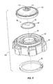
- FIG. 2 is an exploded assembly view of the vented membrane cap of FIG. 1;
- FIG. 3 is perspective view of the vented membrane cap of FIG. 1;
- FIG. 4 is a cross-sectional view of the vented membrane cap of FIG. 1, taken along line 4-4 of FIG. 3;
- FIG. 5 is an exploded assembly view of a vented membrane cap according to another embodiment of the invention.
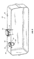
- FIG. 6 is a schematic view of a fuel storage system including the vented membrane cap of FIG. 5;
- FIG. 7 is an exploded assembly view of a remote vent according to another embodiment of the invention.
- FIG. 8 is a cross-sectional view of the remote vent of FIG. 7;
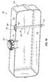
- FIG. 9 is a schematic view of a fuel storage system including the remote vent of FIG. 7;
- FIG. 10 is a schematic view of a fuel storage system including a bottom-vented membrane-separated vent head according to another embodiment of the invention.
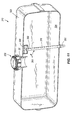
- FIG. 11 is a schematic view of a fuel storage system including a membrane-capped vent tube positioned within a storage tank volume according to yet another embodiment of the invention.
- FIGS. 1-4 illustrate a fuel storage system 20 and components thereof, including a cap 25 for closing an opening 30, such as on a fuel tank 35.
- the cap 25 includes threads 40 for mating with corresponding threads (not shown) on the opening 30.
- the cap 25 serves as a venting structure, which allows for passage of air from an inside of the fuel tank 35 to an outside of the fuel tank 35 and/or vice versa.
- the venting structure allows venting of air into and out of the fuel tank 35 while blocking the passage of liquid, such as gasoline, diesel, etc.
- the venting structure also blocks the passage of fuel vapor volatile organic compounds (VOCs), etc. while allowing the passage of select gases, including air.
- VOCs fuel vapor volatile organic compounds
- the cap 25 of the illustrated embodiment is simply constructed of a main body portion 50 having a venting aperture 55 formed centrally therein.
- the main body portion 50 is also formed to include the threads 40 for engaging the opening 30.
- a gasket 60 is held in position adjacent the threads 40 for engaging the opening 30 when the cap 25 is installed thereon, the gasket 60 forming a circumferential seal between the cap 25 and the opening 30.
- the main body portion 50 includes an outer circumferential wall 65 projecting outwardly (away from the fuel tank 35).
- a cover 70 is coupled to the main body portion 50 adjacent the outer circumferential wall 65 to define a substantially enclosed chamber 75 with the main body portion 50.
- the cover 70 includes a vent hole 80 providing limited communication between the chamber 75 and the atmosphere outside the cap 25.
- the main body portion 50 further includes an inner circumferential wall 85 radially inward of the outer circumferential wall 65, and projecting in the same direction as the outer wall 65.
- a separator membrane 90 is supported by the cap 25.
- the separator membrane includes a peripheral rim portion 92 having a larger thickness than a central portion 94.
- the membrane 90 is supported at its peripheral rim portion 92 by the inner circumferential wall 85 of the main body portion 50 such that it is positioned within the chamber 75.
- the membrane 90 is in communication with the venting aperture 55 on one side (the "interior” side) and in communication with the vent hole 80 on the opposite side (the "exterior” side).
- the membrane 90 is generally planar and disk-shaped in the illustrated embodiment.
- the membrane 90 is constructed of a material, as discussed in greater detail below, which is impermeable to liquids such as gasoline and diesel fuel.
- the membrane 90 is joined to the inner circumferential wall 85, which may be constructed of a plastic material, in a liquid leak-free manner.
- the membrane 90 may be welded to the plastic of the vent, and, in such constructions, a weld material/layer may be added to the interface between the membrane 90 and the inner circumferential wall 85.
- the membrane 90 may be welded by ultra-sonic welding, spin welding, etc. to the inner circumferential wall 85. In such constructions, an additional weld material/layer may not be necessary and, therefore, may not be added.
- any of the fastening and/or sealing methods described herein are also applicable to alternate vent structures (regardless of whether they are caps or not) using a membrane similar to the membrane 90 (regardless of the exact form of the membrane).
- a membrane assembly is created that may be employed in various applications including different styles of vents (e.g., cap, remote rollover, etc.) different sizes, etc.
- the membrane 90 provides a liquid/vapor separation between a tank and a carbon canister or air cleaner.
- the cap 25 defines a flow path from the fuel tank 35 to the outside atmosphere.
- the membrane 90 is positioned in the flow path between the interior of the fuel tank 35 and the exterior of the cap 25 opposite the fuel tank. Accordingly, for any gaseous fluid to pass from the interior of the fuel tank 35 to the outside atmosphere or vice versa, such gaseous fluid must pass through the membrane 90.
- the membrane 90 is constructed of a material that is impermeable to liquid (e.g., gasoline, diesel fuel, etc.) such that the fuel tank 35 is vented to the atmosphere through the flow path of the cap 25, and a separate rollover valve is not necessary to keep liquid from escaping the fuel tank 35 through the flow path.
- the membrane 90 acts as a rollover leak protection mechanism, which has no moving parts to be relied upon.
- the cap 25 as a whole is a venting structure with built-in rollover leak protection, which is advantageously provided in the form of the inert membrane 90.
- the membrane 90 is constructed of a material that is impermeable to liquid (e.g., gasoline, diesel fuel, etc.) and also impermeable to fuel vapor while being permeable to air.
- liquid e.g., gasoline, diesel fuel, etc.
- fuel vapor refers to the majority of chemical compounds that commonly evaporate from liquid gasoline, diesel fuel, etc. These are often referred to as VOCs, the release of which are regulated and restricted by certain federal, state, and/or local regulations for many applications.
- the cap 25 is a venting structure with built-in rollover leak protection as well as evaporated fuel vapor blocking.
- fuel vapor may be released to the outside atmosphere when the cap 25 is removed from the opening 30.
- fuel vapor components are trapped in the membrane 90 during one condition (e.g., warm fuel sitting in the fuel tank 35 with the associated internal combustion engine idling or off) and substantially cleared from the membrane during another condition (e.g., running of the internal combustion engine with make-up air entering the fuel tank 35 through the cap 25).
- the cap 25 and fuel storage system 20 may be incorporated with an evaporative emissions system including additional emissions-treating components and/or flow-controlling components.
- a carbon canister is included to filter fuel vapor and retain selected chemical compounds of the fuel vapor therein. The selected chemical compounds are then partially or wholly burned with the fuel in the internal combustion engine of the vehicle, apparatus, etc. as discussed in detail in U.S. Patent Application Serial No. 11/058,063, filed February 14, 2005 , now published as U.S. Patent Application Publication No. 2006/0011173 , the entire contents of which is hereby incorporated by reference.
- the membrane 90 can be of a material and configuration/structure to prevent leakage of liquid fuel from within the fuel tank 35 while allowing flow of gaseous substances therethrough. In some aspects and in some constructions, the membrane 90 can be of a material and configuration/structure to prevent leakage of liquid fuel and select gaseous substances such as fuel vapor while allowing flow of other gaseous substances such as air therethrough.
- the membrane 90 resists the build-up of varnishes from fuels. Additionally, dirt and debris (whether from inside the fuel tank 35 or the outside atmosphere) are prevented from reducing the gaseous flow capacity of the membrane 90. In some constructions, a felt dust seal is provided integral with or adjacent to the vent. The membrane 90 prevents liquid fuels from escaping a tank during virtually all modes of operation, including: normal running, roll over condition, storage, service/maintenance, etc.
- the membrane 90 may provide an oleophobic and/or hydrophobic filter, as discussed above.
- the membrane 90 may be similar to that described and illustrated in U.S. Patent No. 6,579,342 issued January 17, 2003 , the entire contents of which is hereby incorporated by reference.
- FIG. 5 illustrates a cap 105 similar to that illustrated in FIGS. 1-4 in all aspects except for the cover 110, which is distinctive to this embodiment. As such, all reference numerals except those relating to the cover 110 are carried over from the first embodiment.
- the cover 110 includes a nipple 115 projecting outwardly from an external surface and defining a vent aperture 117. Although the nipple 115 is shown as having a barb thereon, it may alternately be threaded or attachable to mating structure with hose clamps, compression fittings, etc.
- the nipple 115 provides a connection structure for extending the flow path from the fuel tank 35 and chamber 75 to a remote location. As in the first embodiment, the flow path provides communication between the inside of the fuel tank 35 and the outside atmosphere.
- a fuel storage system 120 includes the cap 105 coupled to the opening 30 of the fuel tank 35.
- a hose 125 is coupled to the nipple 115 of the cap 105.
- the hose 125 has a remote end 127 fixed at a location remote from the cap 105 and in either direct or indirect communication with the outside atmosphere.
- the hose 125 couples the cap 105 to a carbon canister, especially in an application in which the associated apparatus having an internal combustion engine is regulated for evaporative emissions levels.
- the fuel storage system 120 is a part of an evaporative emissions system in such constructions.
- the evaporative emissions system may include certain functional aspects and components as discussed in U.S. Patent Application Publication No. 2006/0011173 . Such additional aspects and/or components are equally applicable to the alternate constructions discussed below.
- a carbon canister is not coupled to the hose 125.
- the hose 125 may be substantially open-ended at its remote end 127. The remote location may be a more desirable location than the location of the cap 105 to vent to and/or draw from.
- FIGS. 7-9 illustrate a remote vent structure 220 for installation in a closed system, such as a fuel storage system 230, incorporating the membrane 90.
- the vent structure 220 can be placed in the fuel storage system 230 remotely from a cap 232, which mates to an opening of a fuel tank 233.
- the cap 232 need not be vented as the remote vent structure 220 provides venting for the fuel storage system 230.
- the vent structure 220 includes a housing 234, a ramp 238, and a cover 242.
- the cover 242 includes a port 246, which may be connected to a tube, hose, or other conduit.
- the membrane 90 is disposed between the housing 234 and the cover 242.
- the housing 234 defines a path from the fuel tank 233 to the port 246 in the cover 242.
- the membrane 90 is positioned in the flow path between the interior of the housing 234 and the port 246 in the cover 242. Accordingly, for any acceptable gas and/or liquid to pass between the interior of the fuel storage system 230 and the exterior of the fuel storage system 230, such gas and/or liquid must pass through the membrane 90.
- vent structure 220 provides a different accommodating structure for the membrane 90.
- a flat upper wall of the housing 234 provides a resting surface for the membrane 90.
- the cover 242 includes a pocket 248, which is substantially form-fitting around the peripheral rim portion 92 of the membrane 90.
- the membrane 90 may be substantially self-sealing around the peripheral rim portion 92, or alternately, fastening and sealing means may be provided as discussed above with respect to the cap 25.
- a vent structure 250 with a separator membrane 254 is configured to be mounted within a fuel tank 258 of a fuel storage system 262.
- the separator membrane 254 may be located adjacent a vent head 266 (e.g., an integrally formed pocket in an upper wall 270 of the fuel tank 258).
- a tube 274 is coupled to the membrane 254 and open to the volume defined by the vent head 266.
- the tube 274 is routed through the bottom wall 278 of the fuel tank 258 with a fitting 282 to fluidly couple the volume within the vent head 266 to the outside of the fuel tank 258.
- a cap 232 which is simple and not necessarily vented, is provided as in the embodiment of FIG. 9.
- the vent structure 250 allows venting the fuel tank 258 to and from the vent head 266.
- the volume of the vent head 266 is blocked from the liquid fuel within the fuel tank 258 by the membrane 254, which may be identical to the membrane 90 described above except for the particular shape required to couple the membrane 254 with the vent head 266 and the tube 274.
- the membrane 254 includes a central aperture 286, which sealingly mates to the tube 274.
- An outer periphery of the membrane 254 sealingly mates to the fuel tank 258 at the vent head 266.
- a vent structure 300 with a separator membrane 304 is configured to be mounted within a fuel tank 308 of a fuel storage system 312.
- the membrane 304 is formed to define an interior volume, which is in fluid communication with the inside of a tube 316.
- the membrane 304 is formed with a central aperture 320, which sealingly mates with the tube 316.
- the membrane 304 is positioned generally at the top of the fuel tank 308, and the tube 316 couples the interior volume of the membrane 304 with the atmosphere outside the fuel tank 308 by exiting through a bottom wall 324 of the fuel tank 308.
- the membrane 304 is similar to the membranes 90 and 254 described above, including alternate materials, performance, etc. thereof as discussed throughout.
- the following tables and graphs illustrate the venting requirements of a system, such as the fuel system included for a small engine.
- the vent with the membrane allows sufficient flow of make up air into the tank/system so that the engine operates properly.
- "Vent" is used generally to encompass vents in caps and remote vents, and membrane encompasses any of the membranes illustrated in the figures and/or described herein.
- the vent has sufficient air/vapor flow through it to provide the venting of air and vapors generated, for example, from the diurnal temperature cycles and/or the excessive temperature changes typically seen in small off highway engine equipment.
- the membrane allows venting of internal tank pressure without undo pressure build-up in the tank.
Landscapes
- Engineering & Computer Science (AREA)
- Mechanical Engineering (AREA)
- General Engineering & Computer Science (AREA)
- Chemical & Material Sciences (AREA)
- Combustion & Propulsion (AREA)
- Transportation (AREA)
- Sustainable Development (AREA)
- Life Sciences & Earth Sciences (AREA)
- Sustainable Energy (AREA)
- Closures For Containers (AREA)
- Cooling, Air Intake And Gas Exhaust, And Fuel Tank Arrangements In Propulsion Units (AREA)
- Connector Housings Or Holding Contact Members (AREA)
- Air Bags (AREA)
- Lock And Its Accessories (AREA)
- Pressure Vessels And Lids Thereof (AREA)
- Automobile Manufacture Line, Endless Track Vehicle, Trailer (AREA)
- Body Structure For Vehicles (AREA)
- Finger-Pressure Massage (AREA)
- Devices For Conveying Motion By Means Of Endless Flexible Members (AREA)
Applications Claiming Priority (5)
| Application Number | Priority Date | Filing Date | Title |
|---|---|---|---|
| US76061306P | 2006-01-20 | 2006-01-20 | |
| US76067406P | 2006-01-20 | 2006-01-20 | |
| US76067006P | 2006-01-20 | 2006-01-20 | |
| US86207406P | 2006-10-19 | 2006-10-19 | |
| US86207706P | 2006-10-19 | 2006-10-19 |
Publications (1)
| Publication Number | Publication Date |
|---|---|
| EP1810863A1 true EP1810863A1 (fr) | 2007-07-25 |
Family
ID=37944401
Family Applications (5)
| Application Number | Title | Priority Date | Filing Date |
|---|---|---|---|
| EP20080075671 Not-in-force EP1987977B1 (fr) | 2006-01-20 | 2007-01-19 | Procédé d'assemblage d'un bouchon à cliquet modulaire |
| EP20070250227 Withdrawn EP1810863A1 (fr) | 2006-01-20 | 2007-01-19 | Orifice comprenant un séparateur de membrane |
| EP20080075670 Not-in-force EP1987976B1 (fr) | 2006-01-20 | 2007-01-19 | Procédé d'assemblage d'un bouchon à cliquet modulaire |
| EP20070250226 Active EP1810865B1 (fr) | 2006-01-20 | 2007-01-19 | Procédé d'assemblage d'un bouchon à cliquet modulaire |
| EP20070250223 Not-in-force EP1810864B1 (fr) | 2006-01-20 | 2007-01-19 | Bouchon verrouillable |
Family Applications Before (1)
| Application Number | Title | Priority Date | Filing Date |
|---|---|---|---|
| EP20080075671 Not-in-force EP1987977B1 (fr) | 2006-01-20 | 2007-01-19 | Procédé d'assemblage d'un bouchon à cliquet modulaire |
Family Applications After (3)
| Application Number | Title | Priority Date | Filing Date |
|---|---|---|---|
| EP20080075670 Not-in-force EP1987976B1 (fr) | 2006-01-20 | 2007-01-19 | Procédé d'assemblage d'un bouchon à cliquet modulaire |
| EP20070250226 Active EP1810865B1 (fr) | 2006-01-20 | 2007-01-19 | Procédé d'assemblage d'un bouchon à cliquet modulaire |
| EP20070250223 Not-in-force EP1810864B1 (fr) | 2006-01-20 | 2007-01-19 | Bouchon verrouillable |
Country Status (6)
| Country | Link |
|---|---|
| US (5) | US20070175514A1 (fr) |
| EP (5) | EP1987977B1 (fr) |
| CN (5) | CN101066666A (fr) |
| AT (4) | ATE471836T1 (fr) |
| DE (4) | DE602007006062D1 (fr) |
| ES (1) | ES2342685T3 (fr) |
Cited By (1)
| Publication number | Priority date | Publication date | Assignee | Title |
|---|---|---|---|---|
| DE102018206970A1 (de) * | 2018-05-04 | 2019-11-07 | Mahle International Gmbh | Treibstoffversorgungssystem für eine Brennkraftmaschine |
Families Citing this family (75)
| Publication number | Priority date | Publication date | Assignee | Title |
|---|---|---|---|---|
| US7559490B2 (en) * | 2004-08-24 | 2009-07-14 | Roll Llc | Nozzle assembly |
| US7213773B1 (en) | 2004-08-24 | 2007-05-08 | Roll, Llc | Nozzle spray assembly |
| FR2877650B1 (fr) * | 2004-11-05 | 2008-07-04 | Marwal Systems Snc | Dispositif de ventilation de reservoir |
| US7287404B2 (en) * | 2004-12-08 | 2007-10-30 | Flow Security Systems, Inc. | Security device for a threaded element |
| ATE471836T1 (de) * | 2006-01-20 | 2010-07-15 | Bemis Mfg Co | Verfahren zur montage eines modularen sperrklinkenverschlusses |
| JP2008009309A (ja) * | 2006-06-30 | 2008-01-17 | Funai Electric Co Ltd | 撮影装置 |
| US20080011708A1 (en) * | 2006-07-11 | 2008-01-17 | Roll, Llc | Cap for a container |
| US20090166311A1 (en) * | 2007-12-27 | 2009-07-02 | Helvoet Pharma Belgium N.V. | Pharmaceutical closure with a laser-applied marking |
| US7938282B1 (en) * | 2008-01-18 | 2011-05-10 | Berlin Packaging, Llc | Closure for a container |
| US20090223959A1 (en) * | 2008-03-07 | 2009-09-10 | Schulz William J | Cap for a fluid container |
| US8777051B2 (en) * | 2008-04-02 | 2014-07-15 | Brunswick Corporation | Fuel venting systems having protective membranes |
| US9096124B2 (en) * | 2008-04-02 | 2015-08-04 | Brunswick Corporation | Fuel cap apparatus for use with fuel venting systems |
| DE102008032584A1 (de) * | 2008-07-11 | 2010-01-14 | Huf Hülsbeck & Fürst Gmbh & Co. Kg | Sicherheitssystem mit einem Tankverschluss |
| GB2461952A (en) * | 2008-07-23 | 2010-01-27 | Barry Colin Brown | Fuel filler cap |
| US20100024898A1 (en) * | 2008-07-29 | 2010-02-04 | General Electric Company | Fuel tank vent including a membrane separator |
| JP5345413B2 (ja) * | 2009-02-17 | 2013-11-20 | 本田技研工業株式会社 | フィラーキャップの拘束部構造 |
| EP2098402A1 (fr) * | 2009-03-06 | 2009-09-09 | Flambeau, Inc. | Fermeture de récipient de liquide |
| USD611376S1 (en) | 2009-03-12 | 2010-03-09 | Bemis Manufacturing Company | Portion of a metering device |
| US8272398B2 (en) * | 2009-03-18 | 2012-09-25 | Eaton Corporation | Liquid discriminating vent valve |
| CN102459791A (zh) * | 2009-04-10 | 2012-05-16 | 关卡系统公司 | 推销式安全装置 |
| US8485214B2 (en) * | 2009-06-22 | 2013-07-16 | Eaton Corporation | Small engine emissions control valve |
| FR2954428B1 (fr) * | 2009-12-21 | 2012-04-20 | Itw De France | Dispositif limiteur de couple et bouchon pour tete de tubulure comportant un tel dispositif |
| US20110168715A1 (en) * | 2010-01-13 | 2011-07-14 | Eaton Corporation | Fuel cap with emissions protection |
| US8434634B2 (en) | 2010-05-13 | 2013-05-07 | Bemis Manufacturing Company | Ratcheting gauge cap |
| US20120006839A1 (en) * | 2010-07-06 | 2012-01-12 | Briggs & Stratton Corporation | Fuel tank vent system |
| US8915234B2 (en) | 2010-10-25 | 2014-12-23 | Briggs & Stratton Corporation | Fuel cap |
| JP2012122367A (ja) * | 2010-12-07 | 2012-06-28 | Makita Corp | 手持式作業機 |
| US8985398B2 (en) * | 2011-02-04 | 2015-03-24 | S.C. Johnson & Son, Inc. | Attachment mechanism for a container |
| EP2492128B1 (fr) | 2011-02-22 | 2013-08-07 | Inergy Automotive Systems Research (Société Anonyme) | Système de stockage de précurseur d'ammoniac incluant une membrane semi-perméable |
| DE202011110564U1 (de) | 2011-02-22 | 2014-09-12 | Inergy Automotive Systems Research (Société A.) | Ammoniakvorläufer-Lagerungssystem beinhaltend eine semi-permiable Membran |
| ES2581487T3 (es) | 2011-06-30 | 2016-09-06 | Hellermanntyton Corporation | Herramienta de tensado y corte de bridas para cables |
| USD692738S1 (en) | 2011-06-30 | 2013-11-05 | Hellermanntyton Corporation | Cable tie tensioning and cut-off tool |
| KR101195007B1 (ko) | 2011-07-07 | 2012-11-05 | 권태욱 | 이탈방지용 병마개 |
| CN105383790B (zh) * | 2011-10-28 | 2017-09-19 | 碧美斯制造公司 | 系链 |
| FR2987427B1 (fr) * | 2012-01-27 | 2015-03-20 | Valeo Illuminacion | Ventilation d'un boitier de dispositif d'eclairage ou de signalisation d'un vehicule |
| CN102529701B (zh) * | 2012-03-08 | 2014-02-19 | 斯丹德汽车系统(苏州)有限公司 | 单响扭力控制密封的汽车用油箱盖 |
| US9365109B2 (en) | 2012-06-22 | 2016-06-14 | Bemis Manufacturing Company | Cap with adsorption media |
| US8701924B2 (en) * | 2012-08-28 | 2014-04-22 | David Barrett Dalbec | Portable magnetic storage device and a method of storing material |
| US9121243B1 (en) | 2012-11-06 | 2015-09-01 | Ross Headifen | Multifunction well plug dual locking elements |
| USD721423S1 (en) * | 2013-04-08 | 2015-01-20 | Adam Donald Jacques | Lockable cap |
| EP3021767B1 (fr) | 2013-07-19 | 2018-12-12 | Pro-Dex Inc. | Tournevis de limitation de couple |
| US9249824B2 (en) | 2013-08-15 | 2016-02-02 | Centoco Plastics Limited | Locking nut for toilet seat |
| EP2873545B1 (fr) * | 2013-10-17 | 2018-05-02 | Magna Steyr Fuel Systems GmbH | Système de fermeture |
| USD764629S1 (en) | 2014-03-07 | 2016-08-23 | Eaton Corporation | Valve housing |
| USD764026S1 (en) | 2014-03-07 | 2016-08-16 | Eaton Corporation | Valve housing |
| USD731621S1 (en) | 2014-03-07 | 2015-06-09 | Eaton Corporation | Valve housing |
| US20150323401A1 (en) * | 2014-05-07 | 2015-11-12 | Jorge Alejandro Narvaez | Method for Installing an Apparatus to the Correct Torque Setting Without the Use of Torque Measuring Tools |
| US9821256B2 (en) | 2014-05-07 | 2017-11-21 | Dv Industries, Llc | Elastically deformable component providing indication of proper fluid filter installation and related methods |
| US10182609B2 (en) * | 2014-07-28 | 2019-01-22 | Speedplay, Inc. | Aperture cover for bicycle cleat assembly |
| USD741713S1 (en) * | 2014-07-29 | 2015-10-27 | Secure Medication Systems, Llc | Locking cap |
| US9517871B2 (en) * | 2014-09-08 | 2016-12-13 | The Yankee Candle Company, Inc. | Child-resistant air freshener container |
| MX380306B (es) | 2014-12-12 | 2025-03-04 | Hellermanntyton Corp | Mecanismo compuesto de calibración y tensión de herramienta para cortar y tensar lazos de cable. |
| CN105179761B (zh) * | 2015-08-14 | 2017-11-07 | 宁波布拉沃冲气具制造有限公司 | 带安全阀功能的充气阀 |
| CN108290090B (zh) * | 2015-11-11 | 2021-03-02 | 德福工业有限公司 | 提供流体过滤器安装正确的指示的弹性变形部件及相关方法 |
| US10035563B2 (en) | 2016-04-26 | 2018-07-31 | James Randall Ketring | Fuel storage cap flotation device and method of use |
| CN114404015B (zh) | 2016-06-07 | 2024-06-21 | 普罗德克斯有限公司 | 扭矩限制装置 |
| CN106080175B (zh) * | 2016-07-19 | 2018-10-23 | 郭同 | 防盗油箱盖 |
| CN107934185B (zh) * | 2016-10-12 | 2021-10-12 | 福特环球技术公司 | 扭矩元件及盖总成 |
| US10479567B2 (en) | 2017-08-04 | 2019-11-19 | Nuk Usa Llc | Drink container with torque-limiting lid |
| US10246907B2 (en) * | 2017-08-04 | 2019-04-02 | King Roof Industrial Co., Ltd | Spinning knob |
| US10663069B2 (en) | 2017-11-30 | 2020-05-26 | Kohler Co. | Fuel cap with duck bill valve |
| KR102452696B1 (ko) * | 2017-12-12 | 2022-10-11 | 현대자동차주식회사 | 음정을 발생하는 락킹 구조를 구비한 차량용 연료캡 |
| USD873373S1 (en) | 2018-07-23 | 2020-01-21 | Oso Perforating, Llc | Perforating gun contact device |
| USD877286S1 (en) * | 2018-07-23 | 2020-03-03 | Oso Perforating, Llc | Perforating gun contact ring |
| CA3105137A1 (fr) | 2018-08-20 | 2020-02-27 | Pro-Dex, Inc. | Dispositifs, systemes et procedes de limitation de couple |
| US11383901B2 (en) | 2018-12-05 | 2022-07-12 | Bemis Manufacturing Company | Pressure relief cap |
| DE102019114751A1 (de) * | 2019-06-03 | 2020-12-03 | Vaillant Gmbh | Membran-Gasabscheider |
| US11202917B2 (en) * | 2019-12-12 | 2021-12-21 | Medtronic, Inc | Medical device with cam based rotating fastener |
| CN111550501B (zh) * | 2020-04-03 | 2022-04-08 | 宁波吉利汽车研究开发有限公司 | 一种防漏油的传动轴万向节 |
| CN112572138A (zh) * | 2020-12-26 | 2021-03-30 | 骅特汽车配件(浙江)有限公司 | 加油口盖的提示音发生结构 |
| USD979174S1 (en) * | 2021-07-12 | 2023-02-21 | Shanxi Yunrui Trading Co., Ltd. | Decorative urn |
| US12085216B2 (en) | 2022-02-17 | 2024-09-10 | Arctic Cat Inc. | Multi-use fuel filler tube |
| USD1005203S1 (en) * | 2023-08-17 | 2023-11-21 | Feng Zhang | Fuel tank cap |
| US20250178806A1 (en) * | 2023-12-01 | 2025-06-05 | Bemis Manufacturing Company | Cap with key lock assembly |
| CA3257469A1 (en) * | 2024-08-20 | 2025-04-07 | SUZHOU BASECARE MEDICAL DEVICE Co.,Ltd. | Combined cap plug and liquid nitrogen tank |
Citations (4)
| Publication number | Priority date | Publication date | Assignee | Title |
|---|---|---|---|---|
| FR1357064A (fr) * | 1963-02-20 | 1964-04-03 | Capsule de bouchage perméable aux gaz | |
| WO1995003949A1 (fr) * | 1993-07-27 | 1995-02-09 | E.I. Du Pont De Nemours And Company | Dispositif de fermeture a membrane |
| US20010052292A1 (en) * | 2000-06-08 | 2001-12-20 | Nissan Motor Co., Ltd. | Fuel vapor treatment system |
| US20050098160A1 (en) * | 2003-11-12 | 2005-05-12 | Taxon Morse N. | Fuel vent assembly with floatless rollover protection |
Family Cites Families (165)
| Publication number | Priority date | Publication date | Assignee | Title |
|---|---|---|---|---|
| US738917A (en) | 1903-01-08 | 1903-09-15 | August J Kempien | Bottle-stopper. |
| US1694030A (en) | 1921-08-09 | 1928-12-04 | Louis A Bean | Radiator cap for automobiles |
| US1509796A (en) * | 1923-02-26 | 1924-09-23 | Tokuhisa Tokusaburo | Cover for gasoline tanks |
| US1702205A (en) | 1926-09-24 | 1929-02-12 | Freedman Fred | Tank-cap lock |
| US1702532A (en) | 1927-01-04 | 1929-02-19 | George R Boomer | Protective closure structure |
| US2070692A (en) | 1935-06-21 | 1937-02-16 | Porter E Stone | Lock |
| US2308892A (en) | 1941-01-21 | 1943-01-19 | J B Miller Keyless Lock Compan | Filler pipe cap lock |
| US2681559A (en) | 1951-04-11 | 1954-06-22 | Stant Mfg Company Inc | Locking cap for tank filler spouts |
| US2696100A (en) | 1953-03-09 | 1954-12-07 | Charles H Nehls | Cap construction |
| US2816433A (en) | 1956-05-28 | 1957-12-17 | Stant Mfg Company Inc | Push-on type, locking gas tank cap |
| US2820565A (en) | 1956-10-05 | 1958-01-21 | Nat Hardware Corp | Lockable bottle or like container |
| US3025827A (en) * | 1960-09-06 | 1962-03-20 | Delman Co | Cleaning solvent reservoir cap |
| US3136148A (en) | 1963-04-26 | 1964-06-09 | Charles H Nehls | Locking closure |
| US3208617A (en) * | 1964-10-12 | 1965-09-28 | Robert R Baron | Container closure means |
| US3373894A (en) | 1965-10-01 | 1968-03-19 | Stant Mfg Company Inc | Locking, pressure-relief radiator cap |
| US3343697A (en) | 1966-11-30 | 1967-09-26 | Roberts Simon | Safety closure |
| US3426932A (en) | 1967-07-17 | 1969-02-11 | William R Rouse | Tamper-proof poison bottle closure |
| US3748829A (en) * | 1970-07-02 | 1973-07-31 | Calgon Corp | Adsorbing evaporative emission during fueling of automotive vehicles |
| US3918602A (en) | 1972-04-24 | 1975-11-11 | Mack Wayne Plastic Company | Tamperproof closure |
| US3950973A (en) | 1973-04-24 | 1976-04-20 | Kis France | Flat key |
| JPS5249903B2 (fr) | 1974-02-27 | 1977-12-20 | ||
| FR2265631B1 (fr) | 1974-03-29 | 1979-09-28 | Neiman Sa Diffusion | |
| US3986634A (en) * | 1974-06-05 | 1976-10-19 | General Motors Corporation | Torque limiter mechanism |
| DE2444477A1 (de) | 1974-09-18 | 1976-04-01 | Blau Kg Kraftfahrzeugtech | Verschlussdeckel mit zur sicherung nach aussen zu abgedichtet eingesetztem riegelschloss |
| US3998078A (en) | 1975-06-30 | 1976-12-21 | E. Edelmann & Co. | Limited torque locking fuel cap |
| US4000632A (en) | 1975-08-04 | 1977-01-04 | Stant Manufacturing Company, Inc. | Locking gas cap |
| US4000633A (en) | 1975-09-08 | 1977-01-04 | Stant Manufacturing Company, Inc. | Locking gas cap with torque override feature |
| US4037747A (en) * | 1976-05-21 | 1977-07-26 | Anchor Hocking Corporation | Safety closure cap with torque control |
| FR2359760A1 (fr) | 1976-07-26 | 1978-02-24 | Neiman Diffusion | Bouchon antivol pour embase filetee a limiteur de couple de serrage |
| US4342208A (en) | 1976-10-29 | 1982-08-03 | Stant Inc. | Locking gas cap with torque override feature |
| US4083209A (en) | 1977-06-29 | 1978-04-11 | Stant Manufacturing Company, Inc. | Low profile threaded lock cap |
| DE2734394C2 (de) | 1977-07-29 | 1983-12-15 | Blau KG Fabrik für Kraftfahrzeugteile, 4018 Langenfeld | Verschlußdeckel mit über Schlüsselsicherung frei drehender Außenkappe |
| US4132091A (en) | 1977-09-23 | 1979-01-02 | Orion Industries | Self locking fuel cap |
| FR2431933A1 (fr) | 1978-07-28 | 1980-02-22 | Neiman Diffusion | Perfectionnements aux bouchons antivols pour reservoirs de vehicules automobiles |
| US4231240A (en) | 1978-07-28 | 1980-11-04 | Nissan Shatai Kabushiki Kaisha | Screw plug assembly |
| FR2449832A2 (fr) * | 1978-08-08 | 1980-09-19 | Paumellerie Electrique | Dispositif d'obturation pour reservoir d'hydrocarbure ou autre liquide analogue |
| US4177931A (en) * | 1978-10-04 | 1979-12-11 | Stant Manufacturing Company, Inc. | Breakaway gas cap |
| US4223799A (en) | 1979-06-11 | 1980-09-23 | Time Saving Falls, Inc. | Releasable locking means for closure caps |
| US4280346A (en) | 1979-05-21 | 1981-07-28 | Stant Inc. | Torque override threaded locking cap |
| US4280347A (en) | 1979-05-21 | 1981-07-28 | Stant Inc. | Torque override threaded locking cap |
| DE2930133C2 (de) | 1979-07-25 | 1982-12-02 | Daimler-Benz Ag, 7000 Stuttgart | Deckel für einen Verschlußsockel, insbesondere eines Kraftfahrzeug-Tanks |
| US4299102A (en) | 1979-12-03 | 1981-11-10 | Orion Industries, Inc. | Locking fuel cap with plastic mechanism |
| US4294376A (en) | 1980-01-03 | 1981-10-13 | Keller Russell D | Fuel tank cap |
| US4468058A (en) | 1981-04-17 | 1984-08-28 | Kuhlman Corporation | Locking fuel cap |
| US4365722A (en) * | 1981-06-26 | 1982-12-28 | Kramer Steven G | Reminder closure |
| US4480470A (en) * | 1982-06-01 | 1984-11-06 | Tussing Dennis M | Gas cap |
| US4485647A (en) | 1982-07-02 | 1984-12-04 | General Motors Corporation | Locking fuel cap |
| US4453388A (en) | 1982-09-20 | 1984-06-12 | General Motors Corporation | Locking fuel cap |
| US4650082A (en) * | 1983-02-04 | 1987-03-17 | Minnesota Mining And Manufacturing Company | Cap having a liner with embossed indicia |
| US4588465A (en) * | 1983-02-04 | 1986-05-13 | Minnesota Mining And Manufacturing Company | Method for forming a sealed container |
| US4527406A (en) * | 1983-04-28 | 1985-07-09 | General Motors Corporation | Locking fuel cap |
| US4706841A (en) | 1983-06-10 | 1987-11-17 | Velvac, Inc. | Lock protector for fuel cap |
| JPS604455U (ja) | 1983-06-22 | 1985-01-12 | 株式会社東海理化電機製作所 | 燃料タンクのキヤツプ |
| US4592218A (en) | 1985-03-07 | 1986-06-03 | Chechovsky Dardis W | Tank closure lock |
| US4638919A (en) * | 1986-03-31 | 1987-01-27 | Feenick Robert A | Vehicle fuel tank construction |
| US4690292A (en) | 1986-06-20 | 1987-09-01 | Product Investment Incorporated | Safety closure |
| US4678097B1 (en) * | 1986-07-09 | 1999-09-07 | Stant Mfg Co | Breakaway gas cap |
| GB8616925D0 (en) | 1986-07-11 | 1986-08-20 | Itw Ltd | Closure assemblies |
| US4765505A (en) | 1986-07-22 | 1988-08-23 | Stant Inc. | Delayed actuation fuel cap |
| US4676390A (en) | 1986-07-22 | 1987-06-30 | Stant Inc. | Pressure-release fuel cap |
| US4930213A (en) * | 1987-04-24 | 1990-06-05 | Mazda Motor Corporation | System for transferring vehicle body from a coating station to an assembly line and an overhead conveyor |
| US4754627A (en) | 1987-06-22 | 1988-07-05 | Butler Iii Charles A | Closure for a vehicle gasoline filler tube |
| DE8710127U1 (de) | 1987-07-24 | 1987-09-24 | Fa. Andreas Stihl, 7050 Waiblingen | Schraubverschluß für einen Kraftstoffbehälter |
| US4867337A (en) * | 1987-11-17 | 1989-09-19 | Roper Corporation | Gas cap assembly with retainer means |
| US4775061A (en) | 1987-11-23 | 1988-10-04 | Coote David J | Safety bottle cap |
| US4984698A (en) | 1988-01-26 | 1991-01-15 | Stuckey William C | Lockable closure cap |
| US4830058A (en) | 1988-02-08 | 1989-05-16 | Stant Inc. | Closure cap with clutch-actuated release |
| US4881597A (en) | 1988-05-17 | 1989-11-21 | Hensley Jerry C | Environmentally safe locking cap for monitoring well |
| US4830213A (en) | 1988-06-30 | 1989-05-16 | Brunswick Corporation | Closure cap for a fuel receptacle |
| US4892216A (en) | 1989-01-13 | 1990-01-09 | Shaw Aero Development Inc. | Fuel filler cap with overpressure relief |
| FR2644094A1 (fr) * | 1989-03-10 | 1990-09-14 | Bertaud A Ets | Dispositif de vissage a couple de serrage reglable |
| US5051114B2 (en) | 1989-06-15 | 1996-01-16 | Du Pont Canada | Perfluorodioxole membranes |
| US5000339A (en) | 1989-10-02 | 1991-03-19 | Richard Wheat | Flip-top gas cap |
| US5031790A (en) * | 1989-12-06 | 1991-07-16 | Keller Russell D | Vented fuel cap with cam actuated connector |
| DE4006465C2 (de) | 1990-03-01 | 1995-02-16 | Fraunhofer Ges Forschung | Vorrichtung zur Ent- und Belüftung eines Treibstofftankes |
| US5062541A (en) * | 1990-03-22 | 1991-11-05 | U-Haul International, Inc. | Closure cap |
| US4978027A (en) | 1990-03-28 | 1990-12-18 | The Kelch Corporation | Fuel tank with vent system |
| US5051113A (en) | 1990-06-13 | 1991-09-24 | Du Pont Canada Inc. | Air-intake system for mobile engines |
| US5110003A (en) | 1990-06-28 | 1992-05-05 | Stant Inc. | Torque-override cap |
| US5108001A (en) | 1990-07-03 | 1992-04-28 | Stant Inc. | Pressure release vent cap |
| US5042678A (en) | 1990-07-20 | 1991-08-27 | Munguia Preston T | Fuel tank filler tube closure assembly |
| US5284263A (en) * | 1990-10-30 | 1994-02-08 | The West Company, Incorporated | Decoration, identification and differentiation closure system |
| US5212971A (en) * | 1991-01-08 | 1993-05-25 | Kuk Sun Yoon | Fuel tank plug structure |
| DE9106814U1 (de) | 1991-06-04 | 1991-07-25 | Fa. Andreas Stihl, 7050 Waiblingen | Schraubverschluß für einen Flüssigkeitsbehälter |
| US5171439A (en) * | 1991-07-08 | 1992-12-15 | W. L. Gore & Associates, Inc. | Liquid non-leaking gas-venting seal for a container containing liquid |
| US5183173A (en) * | 1991-07-29 | 1993-02-02 | Epicor Industries, Inc. | Auto venting fuel cap |
| DE9201246U1 (de) | 1992-02-01 | 1992-04-02 | Fa. Andreas Stihl, 7050 Waiblingen | Behälterverschluß |
| US5167340A (en) * | 1992-04-13 | 1992-12-01 | Shaw Aero Devices, Inc. | Fuel cap with a molded seal |
| DE9205925U1 (de) | 1992-04-27 | 1992-12-03 | GKSS-Forschungszentrum Geesthacht GmbH, 2054 Geesthacht | Vorrichtung zur Trennung von über Flüssigkeiten entstehenden Gasgemischen |
| US5381919A (en) * | 1993-10-18 | 1995-01-17 | Stant Manufacturing Inc. | Push-on fuel cap |
| US5449086A (en) * | 1993-10-18 | 1995-09-12 | Stant Manufacturing Inc. | Delayed actuation fuel cap |
| US5520300A (en) * | 1993-10-18 | 1996-05-28 | Stant Manufacturing Inc. | Lockable pressure relief fuel cap |
| US5467621A (en) * | 1994-02-10 | 1995-11-21 | Trilby, Ltd. | Lockable closure for a fuel tank filler pipe |
| US5794806A (en) | 1994-05-06 | 1998-08-18 | Stant Manufacturing Inc. | Quick-on fuel cap |
| US5638975A (en) | 1994-05-06 | 1997-06-17 | Stant Manufacturing Inc. | Lost motion fuel cap with cap closure indicator |
| US5540347A (en) * | 1994-05-06 | 1996-07-30 | Stant Manufacturing Inc. | Vent valve assembly for a fuel tank filler neck cap |
| IT1269115B (it) | 1994-06-16 | 1997-03-21 | Perini Fabio Spa | Dispositivo per il cambio automatico di bobine di materiale nastriforme |
| US5882454A (en) * | 1994-10-13 | 1999-03-16 | The Procter & Gamble Company | Process for manufacturing a venting cap |
| US5462190A (en) * | 1995-01-23 | 1995-10-31 | General Motors Corporation | Fuel cap tether apparatus |
| CO4480049A1 (es) * | 1995-01-30 | 1997-07-09 | Grupo Stevi S A De C V | Tapa inviolable e irrellenable con sobretapa |
| DE69619508T2 (de) * | 1995-04-21 | 2002-11-28 | Stant Manufacturing Inc., Connersville | Verschlussanordnung eines tankstutzens |
| US5791507A (en) * | 1995-12-04 | 1998-08-11 | Stant Manufacturing Inc. | Quick-on cap with two-part closure body |
| AT403144B (de) * | 1996-01-09 | 1997-11-25 | Blau Automobiltechnik Gmbh | Verschluss für einen einfüllstutzen, insbesondere eines fahrzeug-kraftstofftankes |
| FR2743786B1 (fr) * | 1996-01-23 | 1999-04-16 | Stihl Maschf Andreas | Bouchon pour une ouverture de remplissage d'un reservoir de carburant |
| US5732841A (en) * | 1996-03-19 | 1998-03-31 | Tesma International Inc. | Fuel cap |
| US5720328A (en) * | 1996-07-31 | 1998-02-24 | Mecrom Ott U. Holey Ohg | Self-closing gas cap for automatic filling machines |
| US6035906A (en) * | 1996-07-31 | 2000-03-14 | Mecrom Ott U. Holey Ohg | Self-closing gas for automatic filling machines |
| DE29614077U1 (de) * | 1996-08-15 | 1996-09-26 | Fa. Andreas Stihl, 71336 Waiblingen | Tankverschluß für einen Einfüllstutzen eines Behälters |
| DE29615509U1 (de) * | 1996-09-06 | 1996-10-17 | Fa. Andreas Stihl, 71336 Waiblingen | Verschlußdeckel für einen Betriebsstoffbehälter |
| US5776155A (en) * | 1996-12-23 | 1998-07-07 | Ethicon Endo-Surgery, Inc. | Methods and devices for attaching and detaching transmission components |
| US6953496B2 (en) | 1997-03-07 | 2005-10-11 | Vapor Systems Technologies, Inc. | Sub-atmospheric fuel storage system |
| US6293996B1 (en) * | 1997-03-07 | 2001-09-25 | Vapor Systems Technologies, Inc. | Fuel storage system with vent filter assembly |
| US5985002A (en) * | 1997-03-07 | 1999-11-16 | Vapor Systems Technologies, Inc. | Fuel storage system with vent filter assembly |
| JP4078685B2 (ja) | 1997-03-31 | 2008-04-23 | 豊田合成株式会社 | 燃料キャップ |
| JP3386995B2 (ja) * | 1997-03-31 | 2003-03-17 | 豊田合成株式会社 | 燃料キャップ |
| US5904057A (en) | 1997-04-21 | 1999-05-18 | Stant Manufacturing Inc. | Lockable fuel cap |
| EP1028896A4 (fr) * | 1997-07-23 | 2002-07-31 | Stant Mfg Inc | Bouchon de reservoir |
| CA2269033A1 (fr) * | 1998-04-13 | 1999-10-13 | Tesma International Inc. | Assemblage de bouchons de reservoirs d'essence |
| JP2000038040A (ja) | 1998-07-22 | 2000-02-08 | Suzuki Motor Corp | 車両用燃料タンクのキャップ装置 |
| EP1154935B1 (fr) | 1998-10-06 | 2006-01-04 | Stant Manufacturing Inc. | Couvercle de goulot de remplissage a limitation de torsion et a couplage rapide |
| DE19846498C2 (de) | 1998-10-09 | 2000-10-19 | Heinz Brunner | Tankverschluß |
| US6415941B1 (en) * | 1998-10-09 | 2002-07-09 | Moeller Marine Products | Method of making a fuel tank assembly |
| IT1305144B1 (it) | 1998-10-28 | 2001-04-10 | I T W Fastex Italia Spa | Gruppo bocchettone per il rifornimento di carburante, in particolareper un veicolo a motore. |
| EP1232899A3 (fr) * | 1998-11-18 | 2005-03-23 | REUTTER, Heinrich | Bouchon pour le réservoir à carburant d'un véhicule automobile |
| US6230918B1 (en) * | 1999-01-21 | 2001-05-15 | Stant Manufacturing Inc. | Quick-on filler neck cap |
| US6079449A (en) | 1999-02-01 | 2000-06-27 | Waterfall Company, Inc. | System for delivering and maintaining the sterility and integrity of flowable materials |
| IL131051A0 (en) | 1999-07-23 | 2001-01-28 | Raviv Prec Injection Molding | Valve and method for fitting it to a tank |
| AT4061U1 (de) | 1999-09-08 | 2001-01-25 | Tesma Motoren Getriebetechnik | Verschlussstopfen für einen füllstutzen eines kraftstoffbehälters |
| US6626157B2 (en) | 2000-01-26 | 2003-09-30 | Siemens Canada Limited | Apparatus and method to detect fuel leak in a zero-vapor fuel system |
| US6705267B1 (en) * | 2000-04-14 | 2004-03-16 | Westerbeke Corporation | Combustion engines |
| DE10039737A1 (de) * | 2000-08-16 | 2002-02-28 | Franzen Soehne Gmbh & Co Kg S | Drehverschluss |
| US6364145B1 (en) * | 2000-08-21 | 2002-04-02 | Richard J. Shaw | Motor vehicle fuel cap inlet and outlet vent apparatus |
| WO2002022454A1 (fr) * | 2000-09-18 | 2002-03-21 | Stant Manufacturing Inc. | Systeme a signal d'avertissement de fin de couple pour capuchon de goulot de remplissage |
| US6503295B1 (en) * | 2000-09-20 | 2003-01-07 | Chevron U.S.A. Inc. | Gas separations using mixed matrix membranes |
| CN2473153Y (zh) * | 2001-01-16 | 2002-01-23 | 福隆玻璃纤维股份有限公司 | 帽盖的结构改良 |
| US6579342B2 (en) | 2001-02-07 | 2003-06-17 | Pall Corporation | Oleophobic membrane materials by oligomer polymerization for filter venting applications |
| EP1232898A3 (fr) * | 2001-02-16 | 2004-01-02 | Stant Manufacturing Inc. | Soupape d'aération à ouverture facile pour réservoir de carburant |
| US6779544B2 (en) * | 2001-03-02 | 2004-08-24 | Stant Manufacturing Inc. | Tank refueling shutoff valve and vent system |
| ES2240278T3 (es) | 2001-06-09 | 2005-10-16 | Ti Automotive (Fuldabruck) Gmbh | Tapon para un deposito de un automovil. |
| CN2516384Y (zh) * | 2001-11-01 | 2002-10-16 | 潍坊众谊汽车配件有限公司 | 中、重型车用燃油箱盖 |
| JP2003212250A (ja) * | 2002-01-22 | 2003-07-30 | Toyoda Gosei Co Ltd | キャップ装置 |
| US6935527B1 (en) | 2002-03-22 | 2005-08-30 | Richard E. Brock | Locking filler cap |
| US6662978B2 (en) * | 2002-05-13 | 2003-12-16 | Shin-Shuoh Lin | Stopper with interchangeable plug |
| US6681949B2 (en) * | 2002-05-21 | 2004-01-27 | Kenneth R. Tibor | Torquing-limiting apparatus |
| US7056611B2 (en) * | 2002-07-16 | 2006-06-06 | Siemens Power Generation, Inc. | System for controlling the operating temperature of a fuel cell |
| US6796451B2 (en) * | 2002-07-18 | 2004-09-28 | Stant Manufacturing Inc. | Pressure deactivated torque override coolant cap |
| US7025222B2 (en) * | 2002-07-22 | 2006-04-11 | Toyoda Gosei Co., Ltd. | Cap device |
| US6981532B2 (en) | 2002-08-01 | 2006-01-03 | Briggs & Stratton Corporation | Drip feed apparatus for a fuel container |
| JP2004098945A (ja) * | 2002-09-11 | 2004-04-02 | Honda Motor Co Ltd | 小型水上艇の給油口構造 |
| US6745505B2 (en) * | 2002-10-15 | 2004-06-08 | Margaret Moran | Color coded beverage cap collection with permanent passive indicia indicating beverage bottle user identities |
| CA2472830C (fr) * | 2003-07-02 | 2010-03-23 | Richard Dillon | Avertisseur de remplissseur e reservoir |
| DE102004038864B4 (de) * | 2003-08-11 | 2010-05-12 | Toyoda Gosei Co., Ltd., Nishikasugai-gun | Deckelvorrichtung |
| US7281640B2 (en) * | 2003-09-29 | 2007-10-16 | Toyoda Gosei Co., Ltd. | Cap device |
| DE20318043U1 (de) * | 2003-11-14 | 2005-04-07 | Reutter Metallwaren | Verschlußdeckel für den Füllstutzen eines Behälters und Füllstutzen hierfür |
| US7493894B2 (en) | 2004-02-13 | 2009-02-24 | Kelch Corporation | Tank assembly and components |
| ES1057183Y (es) * | 2004-03-11 | 2004-10-16 | Maier S Coop Ltda | Modulo de tapa para el llenado de un deposito de carburante. |
| US7357709B2 (en) * | 2004-04-12 | 2008-04-15 | Gore Enterprise Holdings | Metal vent |
| US20060006252A1 (en) * | 2004-07-08 | 2006-01-12 | Wilson C Travis | Waterproof labeled cap for end of an irrigation pipe |
| US20060163250A1 (en) * | 2005-01-27 | 2006-07-27 | Michael Colavita | Pro-tek see-thru gas cap |
| ATE471836T1 (de) * | 2006-01-20 | 2010-07-15 | Bemis Mfg Co | Verfahren zur montage eines modularen sperrklinkenverschlusses |
| US20090223959A1 (en) * | 2008-03-07 | 2009-09-10 | Schulz William J | Cap for a fluid container |
| DE102009006614A1 (de) * | 2009-01-29 | 2010-08-12 | Bayer Cropscience Ag | Schraubverschluss mit Sicherheitsring |
| US8434634B2 (en) * | 2010-05-13 | 2013-05-07 | Bemis Manufacturing Company | Ratcheting gauge cap |
| US8353418B2 (en) * | 2010-07-23 | 2013-01-15 | Bemis Manufacturing Company | Pressure relief cap |
| CN105383790B (zh) * | 2011-10-28 | 2017-09-19 | 碧美斯制造公司 | 系链 |
-
2007
- 2007-01-19 AT AT08075671T patent/ATE471836T1/de not_active IP Right Cessation
- 2007-01-19 AT AT07250226T patent/ATE427232T1/de not_active IP Right Cessation
- 2007-01-19 US US11/624,711 patent/US20070175514A1/en not_active Abandoned
- 2007-01-19 EP EP20080075671 patent/EP1987977B1/fr not_active Not-in-force
- 2007-01-19 EP EP20070250227 patent/EP1810863A1/fr not_active Withdrawn
- 2007-01-19 CN CNA2007100879061A patent/CN101066666A/zh active Pending
- 2007-01-19 AT AT07250223T patent/ATE465907T1/de not_active IP Right Cessation
- 2007-01-19 EP EP20080075670 patent/EP1987976B1/fr not_active Not-in-force
- 2007-01-19 DE DE200760006062 patent/DE602007006062D1/de active Active
- 2007-01-19 EP EP20070250226 patent/EP1810865B1/fr active Active
- 2007-01-19 ES ES07250223T patent/ES2342685T3/es active Active
- 2007-01-19 DE DE200760007901 patent/DE602007007901D1/de active Active
- 2007-01-19 EP EP20070250223 patent/EP1810864B1/fr not_active Not-in-force
- 2007-01-19 AT AT08075670T patent/ATE474733T1/de not_active IP Right Cessation
- 2007-01-19 DE DE200760000785 patent/DE602007000785D1/de active Active
- 2007-01-19 CN CN2007100879112A patent/CN101121382B/zh active Active
- 2007-01-19 DE DE200760007301 patent/DE602007007301D1/de active Active
- 2007-01-19 CN CN2007100879076A patent/CN101067469B/zh active Active
- 2007-01-19 CN CN201310137949.1A patent/CN103253127B/zh active Active
- 2007-01-19 CN CN201310138368.XA patent/CN103253128B/zh active Active
- 2007-01-19 US US11/624,708 patent/US7624889B2/en not_active Expired - Fee Related
- 2007-01-19 US US11/624,709 patent/US8074334B2/en active Active
-
2011
- 2011-07-29 US US13/194,357 patent/US20110308062A1/en not_active Abandoned
- 2011-07-29 US US13/194,401 patent/US20110277307A1/en not_active Abandoned
Patent Citations (4)
| Publication number | Priority date | Publication date | Assignee | Title |
|---|---|---|---|---|
| FR1357064A (fr) * | 1963-02-20 | 1964-04-03 | Capsule de bouchage perméable aux gaz | |
| WO1995003949A1 (fr) * | 1993-07-27 | 1995-02-09 | E.I. Du Pont De Nemours And Company | Dispositif de fermeture a membrane |
| US20010052292A1 (en) * | 2000-06-08 | 2001-12-20 | Nissan Motor Co., Ltd. | Fuel vapor treatment system |
| US20050098160A1 (en) * | 2003-11-12 | 2005-05-12 | Taxon Morse N. | Fuel vent assembly with floatless rollover protection |
Cited By (1)
| Publication number | Priority date | Publication date | Assignee | Title |
|---|---|---|---|---|
| DE102018206970A1 (de) * | 2018-05-04 | 2019-11-07 | Mahle International Gmbh | Treibstoffversorgungssystem für eine Brennkraftmaschine |
Also Published As
Similar Documents
| Publication | Publication Date | Title |
|---|---|---|
| EP1810863A1 (fr) | Orifice comprenant un séparateur de membrane | |
| US6354280B1 (en) | Evaporation control apparatus | |
| US5819796A (en) | Fuel storage system | |
| US20090101119A1 (en) | Carbon canister cap with integrated device | |
| US10076720B2 (en) | Cap with adsorption media | |
| US5267470A (en) | Pressure sensor mounting for canister purge system | |
| US7610905B2 (en) | Passive evaporative emission control module | |
| US6390073B1 (en) | Evaporative emission storage canister with integral filter and vent solenoid | |
| US20080223343A1 (en) | Fuel vapor control apparatus | |
| US6502607B2 (en) | Fuel tank valve apparatus | |
| JPH1047184A (ja) | 燃料漏れ防止弁 | |
| EP3575587B1 (fr) | Module de vérification de fuites d'un système de contrôle d'émissions par évaporation comprenant une première et une seconde électrovannes | |
| US20070151628A1 (en) | Fuel tank cap | |
| US20060207576A1 (en) | Vapor vent valve with pressure relief function integrated to carbon canister | |
| US7527044B2 (en) | Small engine carbon canister with check valve | |
| US9303598B2 (en) | Device for aeration and ventilation of a fuel system | |
| US6386244B2 (en) | Fuel tank valve apparatus | |
| JP3487392B2 (ja) | 蒸発燃料処理装置 | |
| WO2015127477A1 (fr) | Discriminateur de liquide/vapeurs de réservoir de carburant avec surpression intégrée et soupapes d'air d'appoint | |
| US9114701B2 (en) | Methods and apparatus to provide a protective barrier to fuel tank coupling apparatus | |
| US20080251138A1 (en) | Fuel Volatilizing Control System of Fuel Tank | |
| EP2542438B1 (fr) | Système et procédé pour aération de carburateur | |
| US7451746B2 (en) | Canister assembly | |
| US8246729B2 (en) | Fuel vapour adsorbing device | |
| US20040226439A1 (en) | Integrated PZEV module |
Legal Events
| Date | Code | Title | Description |
|---|---|---|---|
| PUAI | Public reference made under article 153(3) epc to a published international application that has entered the european phase |
Free format text: ORIGINAL CODE: 0009012 |
|
| AK | Designated contracting states |
Kind code of ref document: A1 Designated state(s): AT BE BG CH CY CZ DE DK EE ES FI FR GB GR HU IE IS IT LI LT LU LV MC NL PL PT RO SE SI SK TR |
|
| AX | Request for extension of the european patent |
Extension state: AL BA HR MK YU |
|
| 17P | Request for examination filed |
Effective date: 20080121 |
|
| 17Q | First examination report despatched |
Effective date: 20080218 |
|
| AKX | Designation fees paid |
Designated state(s): AT BE BG CH CY CZ DE DK EE ES FI FR GB GR HU IE IS IT LI LT LU LV MC NL PL PT RO SE SI SK TR |
|
| STAA | Information on the status of an ep patent application or granted ep patent |
Free format text: STATUS: THE APPLICATION IS DEEMED TO BE WITHDRAWN |
|
| 18D | Application deemed to be withdrawn |
Effective date: 20101005 |