EP1810944A1 - Dispositif pour le transport de bobines pour des métiers à filer - Google Patents
Dispositif pour le transport de bobines pour des métiers à filer Download PDFInfo
- Publication number
- EP1810944A1 EP1810944A1 EP06001050A EP06001050A EP1810944A1 EP 1810944 A1 EP1810944 A1 EP 1810944A1 EP 06001050 A EP06001050 A EP 06001050A EP 06001050 A EP06001050 A EP 06001050A EP 1810944 A1 EP1810944 A1 EP 1810944A1
- Authority
- EP
- European Patent Office
- Prior art keywords
- textile machine
- machine
- removal
- coils
- units
- Prior art date
- Legal status (The legal status is an assumption and is not a legal conclusion. Google has not performed a legal analysis and makes no representation as to the accuracy of the status listed.)
- Withdrawn
Links
Images

Classifications
-
- B—PERFORMING OPERATIONS; TRANSPORTING
- B65—CONVEYING; PACKING; STORING; HANDLING THIN OR FILAMENTARY MATERIAL
- B65H—HANDLING THIN OR FILAMENTARY MATERIAL, e.g. SHEETS, WEBS, CABLES
- B65H67/00—Replacing or removing cores, receptacles, or completed packages at paying-out, winding, or depositing stations
- B65H67/04—Arrangements for removing completed take-up packages and or replacing by cores, formers, or empty receptacles at winding or depositing stations; Transferring material between adjacent full and empty take-up elements
- B65H67/0405—Arrangements for removing completed take-up packages or for loading an empty core
- B65H67/0411—Arrangements for removing completed take-up packages or for loading an empty core for removing completed take-up packages
-
- B—PERFORMING OPERATIONS; TRANSPORTING
- B65—CONVEYING; PACKING; STORING; HANDLING THIN OR FILAMENTARY MATERIAL
- B65H—HANDLING THIN OR FILAMENTARY MATERIAL, e.g. SHEETS, WEBS, CABLES
- B65H67/00—Replacing or removing cores, receptacles, or completed packages at paying-out, winding, or depositing stations
- B65H67/06—Supplying cores, receptacles, or packages to, or transporting from, winding or depositing stations
- B65H67/064—Supplying or transporting cross-wound packages, also combined with transporting the empty core
-
- B—PERFORMING OPERATIONS; TRANSPORTING
- B65—CONVEYING; PACKING; STORING; HANDLING THIN OR FILAMENTARY MATERIAL
- B65H—HANDLING THIN OR FILAMENTARY MATERIAL, e.g. SHEETS, WEBS, CABLES
- B65H2701/00—Handled material; Storage means
- B65H2701/30—Handled filamentary material
- B65H2701/31—Textiles threads or artificial strands of filaments
Definitions
- the present invention relates generally to a textile machine and more particularly to a spinning machine for the production of yarn according to the preamble of independent claim 1.
- Textile machines where a yarn must be produced or rewound are usually equipped with their own winding units, which wind up yarn on bobbins to form coils.
- the textile machines usually a machine - called robot in this document - on which stores the full bobbins on a clearing or conveyor belt.
- the robot can move over several or all workstations or spinning stations and is among other things able to remove the (full) coils from the respective winding unit and store them on the Abhoffmband.
- the removal belt runs along the entire machine, passing each work station or spinning station, and serves to convey the coils deposited by the machine to one of the ends of the textile machine.
- the EP 393 363 A1 describes, for example, a textile machine constructed in this way. As can be seen from the figures of the document, it is known to design such textile machines on both sides, ie to provide spinning and working positions on both longitudinal sides, which supply a common removal belt.
- Textile machines according to the preceding paragraph have proven themselves in practice, but have a disadvantage in raw material change or in so-called. Game changes (ie yarn with new properties is produced) on.
- the operation of the textile machine or the operation of the Abissembandes is flawless as long as all workstations or spinning stations of the machine produce the same product or coils with the same yarn.
- the present invention is therefore based on the object to minimize the productivity losses of textile machinery in raw material or lot changes, caused by stopping and retrofitting of jobs.
- the inventive textile machine it is now possible that several raw materials or lots are processed simultaneously. As a result, it is not only possible to process several assortments simultaneously on each side of the machine, but the changeover from one batch / raw material to a new one can also be carried out smoothly, ie. without collective stopping or starting several workstations or spinning stations, done. Thanks to the simultaneous use of several Abräumb sectionsn it is now possible without collective interruption, workstation for workstation, as soon as at this the old fiber template has expired.
- the functionality is relatively simple. Each assortment has its own removal belt. For example, if you want to be able to change from an old to a new range, you will need two clearing edges.
- the bobbin tray will be placed in such a way that the full bobbins of the old assortment are always placed on the one removal belt (figuratively, for example, the right removal belt).
- the control is set so that the new full bobbins are placed on the other - for the new batch / raw material provided - Abhoffmband (in the example so the left Abhoffmband).
- Abhoffmband in the example so the left Abhoffmband.
- the invention is not limited to spinning machines.
- the invention can also be applied to winding machines or automatic winder. In such machines already manufactured yarn is rewound, e.g. from normal coils to cheeses.
- the present application also aims to protect this application, because even in a winder, the invention has similar advantages: Again, different yarns can be rewound on the same winder thanks to the possibility of depositing on several Abräumb sources without the yarn bobbins are confused.
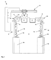
- FIG. 1 shows a schematic cross-section of a textile machine 1.
- the illustrated textile machine in the case shown concretely, it is a spinning machine.
- the textile machine 1 is double-sided, it has (perpendicular to the longitudinal axis) opposite workstations (in Figure 1 workstation 2 and 12).
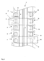
- the textile machine 1 has on both longitudinal sides of a plurality of juxtaposed workstations 2 and 12 (see top view of Figure 2).
- FIG. 1 shows a spinning machine, the workstations 2 and 12 represent spinning stations in the specific case.
- the spinning stations or workstations 2 and 12 shown in FIG. 1 produce the yarn 9 or 11 from the fiber sliver 13 deposited in cans 14 by pulling the sliver 13 through a drafting system 15 and subsequently into the yarn 9 in a production unit 8 or spinning box 8 and 11 is spun.
- the yarn 9 or 11 is withdrawn from the outlet roller pair from the spinning box 8 and wound up by the winding units 3 and 10 into coils 5.
- the yarn is wound in the winding units 3 and 10 on sleeves, which are driven by the sleeve mandrel or a friction roller (not shown in detail). If the coils 5 reach a certain predeterminable size or diameter, they must be removed from the winding units 3 or 10 and replaced by empty sleeves.
- This process is usually carried out automatically by a machine or robot.
- a new, inventive removal device 17 can be installed (see Figure 1) or it can on the textile machine - see description of Figure 6 - another special removal device 16 are provided.
- the robot 6 shown in Figure 1 therefore preferably has the However, the robot has, in addition to the inventive removal function, numerous other functions, such as the resumption of the spinning process after a yarn breakage interruption, etc.
- the inventive device provides that the robot can remove the coil from the winding unit of the respective workstation and - In contrast to the prior art - is able to place the coil on several Abräumb instruments for further removal.
- the robot 6 has for this purpose the movable removal device 17 according to the invention (shown only schematically).
- the robot with the gripping device 17 can deposit the coils 5 removed by the winding units (here winding unit 3) not only on a removal belt but on a plurality of such belts (here the removal belts 4 and 7).
- the device according to the invention not only a practically continuous operation of the spinning or working stations is possible when changing assortments.
- the invention also makes it possible to process several assortments simultaneously on the same textile machine or textile machine side. If two removal margins are operable by the robot 6 or by the removal device 17 or by the removal device 16 (see FIG. 6) mentioned below, two assortments can be processed simultaneously. If there are three trimming belts available and operable, then three assortments can be processed at the same time, four assortments etc. for four trimming belts. Depending on the number of removal bands or processable assortments, a corresponding number of different production units 8 can also be used. In one conceivable embodiment of the invention, for example, a group of production units 8 can produce a yarn 9 according to an air-spinning process, while a second group of production units can produce a yarn 11 according to the open-end spinning process manufactures. These different groups can be operated simultaneously on the same textile machine or the same textile machine side.
- the invention is applicable to two-sided machines (see Figure 1) as well as on one-sided machines (see Figure 4).
- the application on two-sided textile machines has the advantage that both sides can access the same Abräumb from (provided both sides have corresponding, inventive Ab passingvorraumen).
- the spinning machine of Figure 1 also has for its right longitudinal side, e.g. for the workstation 12, a robotic machine analog to the robot 6, which is not shown in Figure 1, however.
- FIG. 2 shows the textile machine of FIG. 1 in a plan view.
- both longitudinal sides of the machine 1 to a plurality of workstations 2 and 12, which are operated by the machines or robots 6 and 18, inter alia, for the deposition of full coils 5.
- this figure also shows the robot 18 for the right side of the machine.
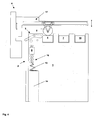
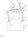
- FIG. 3 again illustrates the invention when using two abrading bands.
- the figure shows with reference to the coil shown in dashed lines a) as the robot 6 to the workstation 2 (may also be a winding unit) positioned and with its inventive acceptance or gripping device 17, the full bobbin 5 of the winding unit 3 lifts.
- the removal device 17 of the robot will place the spool on the removal belt 4 (variant b) or on the removal belt 7 (variant c).
- various types have been worked out as to how the removal device on the robot receives the information as to where a coil is to be deposited. See the comments further ahead or the claims.
- the invention is also used for storing not yet full coils. Even with normal use of the textile machine, such use can be done regularly, for example, if you want to let a raw material completely leak (the Fiber material then runs out at the spinning stations and the coils must be cleared regardless of their size).
- FIG. 4 shows the invention applied to a single-sided textile machine. As you can see, you can use the inventive picking devices regardless of whether the machine is one or more pages.
- the textile machine of Figure 4 even has a third Ab Hurmband 19. Accordingly, 3 different assortments can be processed or processed on this machine. Three Abräumbs would of course also possible on double-sided textile machines.
- Figure 5 deals with a further development of the inventive concept.
- opposed removal devices 17 or robots 6 and 18 are designed such that they do not interfere with each other. This property can be ensured by constructive or control measures - preferably a combination thereof.
- the picking devices 17 of opposing robots 6 and 18 can assume different heights and positions such that they easily pass each other, even if one of the two machines 6 or 18 is currently depositing a reel (see FIG. 5). This ensures that the opposing robots 6 and 18 do not interfere with each other beyond the actual filing process.
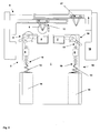
- each work station or winding unit of the textile machine 1 has a special removal device 16 according to the invention, which is able to remove the coils from the associated winding units and to the various removal edges lay.
- opposite removal device 16 may be designed such that they can work coordinated. That is, the removal devices 16 can coordinate their movements and position such that the coils 5 can be placed on both sides of the same Abräumbs 4 and 7, without to interfere with each other beyond the filing process.
- a corresponding procedure is also shown in FIG. 6: It can be seen how actually both winding units 3 and 10 each have a coil to deposit.
- both pickup devices 16 are coordinated in such a way that they do not interfere with each other beyond the filing process.
- removal devices 16 as such already represent their own invention, it is also possible to provide removal devices 16 on textile machines with a removal belt.
- a removal device for textile machines in particular winding or spinning machines, is characterized in that it is fixedly mounted on a winding unit or associated with only one winding unit and remove the coils from this winding unit and can deposit on one or more Abräumb instruments.
- the invention generally provides a textile machine, preferably a spinning or winding machine, to provide, which contains a plurality of work stations with winding units, wherein on the textile machine several, preferably two or three, Abräumb sources are mounted for the removal of coils.
- the invention can be characterized in that inventive removal devices are present which can deposit the coils on several Abräumb sources.
- the picking devices are preferably mounted on the individual winding units or on the workstations.
- the robots can be movable over several workstations.
- the invention is particularly suitable for textile machines, which have workstations, which in turn are modular and / or have interchangeable production units.
- this production unit can also produce different yarns.
- the interchangeable production units have their own drives. On the same textile machine thus production units can be operated, which use different spinning processes.
- individual workstations can be separately controlled and operated.
- this variant is made possible by a central control of the textile machine.
- the invention also provides that the removal device from the respective workstation or from the central control of the textile machine receives the information on which removal belt it has to deposit the respective coil.
- the textile machine has work stations on both longitudinal sides, wherein the removal devices on each longitudinal side for depositing the coils uses the same Abräumb.
- the opposing removal devices on the winding units or robots preferably coordinate in their movements and position such that the depositing of the coils on the same removal margins is ensured from both longitudinal sides without the opposing removal devices or winding units or robots obstructing one another.
- a further variant of the invention provides that the coils are equipped with an identification means, preferably a transponder on the bobbin tube, on the basis of which the removal devices, the robot, or the winding unit receives the information on which predetermined Abhoffmband the removal devices have to deposit the coil.
- an identification means preferably a transponder on the bobbin tube
- the textile machine has workstations with production units which produce a yarn by an air-spinning process, preferably the vortex process, or the open-end spinning process.
- the production units in the work stations produce a yarn, wherein the discharge speed of the produced yarn from the production units at least 300 m / min. is.
- the invention is applied to a winding machine, which preferably serve the rewinding of yarn on cheeses.
Landscapes
- Spinning Or Twisting Of Yarns (AREA)
Priority Applications (1)
| Application Number | Priority Date | Filing Date | Title |
|---|---|---|---|
| EP06001050A EP1810944A1 (fr) | 2006-01-18 | 2006-01-18 | Dispositif pour le transport de bobines pour des métiers à filer |
Applications Claiming Priority (1)
| Application Number | Priority Date | Filing Date | Title |
|---|---|---|---|
| EP06001050A EP1810944A1 (fr) | 2006-01-18 | 2006-01-18 | Dispositif pour le transport de bobines pour des métiers à filer |
Publications (1)
| Publication Number | Publication Date |
|---|---|
| EP1810944A1 true EP1810944A1 (fr) | 2007-07-25 |
Family
ID=36501909
Family Applications (1)
| Application Number | Title | Priority Date | Filing Date |
|---|---|---|---|
| EP06001050A Withdrawn EP1810944A1 (fr) | 2006-01-18 | 2006-01-18 | Dispositif pour le transport de bobines pour des métiers à filer |
Country Status (1)
| Country | Link |
|---|---|
| EP (1) | EP1810944A1 (fr) |
Cited By (6)
| Publication number | Priority date | Publication date | Assignee | Title |
|---|---|---|---|---|
| US20090242602A1 (en) * | 2008-03-28 | 2009-10-01 | Delta Industrial Services, Inc | Systems and methods to position web processing equipment |
| EP3103750A1 (fr) * | 2015-06-11 | 2016-12-14 | Murata Machinery, Ltd. | Machine de bobinage de fil et machine à filer |
| CN110510454A (zh) * | 2019-10-10 | 2019-11-29 | 程斌 | 一种纺织机械加工用绕盘装置 |
| DE102018132459A1 (de) * | 2018-12-17 | 2020-06-18 | Saurer Spinning Solutions Gmbh & Co. Kg | Kreuzspulen herstellende Textilmaschine mit einer Kreuzspulentransporteinrichtung |
| CN114126998A (zh) * | 2019-07-19 | 2022-03-01 | 卓郎纺织解决方案两合股份有限公司 | 用于制造交叉卷绕筒子的纺织机的筒管库 |
| US12030735B2 (en) | 2020-10-30 | 2024-07-09 | Delta Industrial Services, Inc. | Adjustable field of view laser system for web processing |
Citations (6)
| Publication number | Priority date | Publication date | Assignee | Title |
|---|---|---|---|---|
| US4582270A (en) * | 1982-06-26 | 1986-04-15 | Kabushiki Kaisha Toyoda Jidoshokki Seisakusho | Method of transferring yarn packages in a spinning frame |
| DE3828592A1 (de) | 1987-09-07 | 1989-03-16 | Elitex Zavody Textilniho | Textilmaschine mit fahrautomaten fuer den wechsel von garnspulen |
| US4928895A (en) * | 1988-03-30 | 1990-05-29 | W. Schlafhorst & Co. | Method and apparatus for assembling a plurality of packages for transport along a textile machine |
| EP0393363A1 (fr) | 1989-04-17 | 1990-10-24 | Palitex Project-Company GmbH | Méthode pour le déchargement automatique de bobines remplies d'une machine textile bisectionnelle, surtout pour une machine d'embobinage, de filage et de retordage |
| US5033623A (en) * | 1989-04-15 | 1991-07-23 | W. Schlafhorst & Co. | Method and apparatus for associating information with a textile package |
| DE19912631A1 (de) * | 1998-03-30 | 1999-10-07 | Rieter Elitex As | Vorrichtung zur Abführung aufgewickelter Spulen von Aufwickeleinrichtungen einer Textilmaschine |
-
2006
- 2006-01-18 EP EP06001050A patent/EP1810944A1/fr not_active Withdrawn
Patent Citations (6)
| Publication number | Priority date | Publication date | Assignee | Title |
|---|---|---|---|---|
| US4582270A (en) * | 1982-06-26 | 1986-04-15 | Kabushiki Kaisha Toyoda Jidoshokki Seisakusho | Method of transferring yarn packages in a spinning frame |
| DE3828592A1 (de) | 1987-09-07 | 1989-03-16 | Elitex Zavody Textilniho | Textilmaschine mit fahrautomaten fuer den wechsel von garnspulen |
| US4928895A (en) * | 1988-03-30 | 1990-05-29 | W. Schlafhorst & Co. | Method and apparatus for assembling a plurality of packages for transport along a textile machine |
| US5033623A (en) * | 1989-04-15 | 1991-07-23 | W. Schlafhorst & Co. | Method and apparatus for associating information with a textile package |
| EP0393363A1 (fr) | 1989-04-17 | 1990-10-24 | Palitex Project-Company GmbH | Méthode pour le déchargement automatique de bobines remplies d'une machine textile bisectionnelle, surtout pour une machine d'embobinage, de filage et de retordage |
| DE19912631A1 (de) * | 1998-03-30 | 1999-10-07 | Rieter Elitex As | Vorrichtung zur Abführung aufgewickelter Spulen von Aufwickeleinrichtungen einer Textilmaschine |
Cited By (9)
| Publication number | Priority date | Publication date | Assignee | Title |
|---|---|---|---|---|
| US20090242602A1 (en) * | 2008-03-28 | 2009-10-01 | Delta Industrial Services, Inc | Systems and methods to position web processing equipment |
| US8436272B2 (en) * | 2008-03-28 | 2013-05-07 | Delta Industrial Services, Inc. | Systems and methods to position web processing equipment |
| EP3103750A1 (fr) * | 2015-06-11 | 2016-12-14 | Murata Machinery, Ltd. | Machine de bobinage de fil et machine à filer |
| CN106241495A (zh) * | 2015-06-11 | 2016-12-21 | 村田机械株式会社 | 纱线卷取机以及纺纱机械 |
| CN106241495B (zh) * | 2015-06-11 | 2019-07-12 | 村田机械株式会社 | 纱线卷取机以及纺纱机械 |
| DE102018132459A1 (de) * | 2018-12-17 | 2020-06-18 | Saurer Spinning Solutions Gmbh & Co. Kg | Kreuzspulen herstellende Textilmaschine mit einer Kreuzspulentransporteinrichtung |
| CN114126998A (zh) * | 2019-07-19 | 2022-03-01 | 卓郎纺织解决方案两合股份有限公司 | 用于制造交叉卷绕筒子的纺织机的筒管库 |
| CN110510454A (zh) * | 2019-10-10 | 2019-11-29 | 程斌 | 一种纺织机械加工用绕盘装置 |
| US12030735B2 (en) | 2020-10-30 | 2024-07-09 | Delta Industrial Services, Inc. | Adjustable field of view laser system for web processing |
Similar Documents
| Publication | Publication Date | Title |
|---|---|---|
| EP3237658B1 (fr) | Métier à filer à rotor comportant une pluralité d'emplacements de travail et un dispositif d'aspiration | |
| EP2966201B1 (fr) | Machine de filage à bout libre semi-automatique | |
| EP3031761B1 (fr) | Machine textile multi-position | |
| EP3100971B1 (fr) | Procede de fonctionnement d'une machine textile comprenant des organes de manutention propres a chaque poste de travail pour le re-attachement d'un fil et machine textile comprenant des organes de manutention | |
| DE102007053467B4 (de) | Verfahren und Vorrichtung zum Betreiben einer Offenend-Rotorspinnmaschine | |
| EP2955143B1 (fr) | Machine textile semi-automatique fabriquant des bobines | |
| EP1902990B1 (fr) | Dispositif pour une machine de prétraitement de filature | |
| DE102007056561A1 (de) | Kreuzspulen herstellende Textilmaschine | |
| WO2007147483A1 (fr) | Métier à filer | |
| DE102011111725A1 (de) | Textilmaschine mit einer Vielzahl von Arbeitsstellen | |
| EP3144418B1 (fr) | Procede d'adaptation d'une conception usine concernant une fabrication de lot de fil d'un metier a tisser a rotor a extremite ouverte | |
| DE102007018536A1 (de) | Offenend-Spinnmaschine | |
| DE68925017T2 (de) | Automatisches Ansetzen eines Faserbandes in einer Textilmaschine. | |
| EP1810944A1 (fr) | Dispositif pour le transport de bobines pour des métiers à filer | |
| DE102007039049A1 (de) | Spinnanlage | |
| DE102012007987A1 (de) | Verfahren und Vorrichtung zum kontinuierlichen Abziehen und Aufspulen mehrerer Fäden | |
| WO2009030592A1 (fr) | Dispositif de va-et-vient | |
| EP3901336A1 (fr) | Métier à filer doté d'une pluralité de postes de travail les uns à côté des autres, ainsi que procédé de fonctionnement d'un métier à filer doté d'une pluralité de postes de travail les uns à côté des autres | |
| EP0869206B1 (fr) | Système de transport et de stockage pour pots de filature | |
| DE102018132459A1 (de) | Kreuzspulen herstellende Textilmaschine mit einer Kreuzspulentransporteinrichtung | |
| EP4026934B1 (fr) | Procédé de rattache et dispositif de rattache | |
| DE10009335A1 (de) | Vorrichtung zum Wechseln von Spulen in einer Spinnanlage | |
| DE1435356A1 (de) | Spulenspinnmaschine fuer endlose nach dem Schmelz- oder Trockenspinnverfahren hergestellte kuenstliche Faeden | |
| EP0703179A2 (fr) | Bobinoir automatique et procédé pour le transfert du fil d'une bobine pleine à une bobine vide | |
| DE102013018985A1 (de) | Verfahren zum Durchführen eines Kreuzspulenwechsels an einer Arbeitsstelle einer Kreuzspulen herstellenden Textilmaschine sowie zugehörige Kreuzspulen herstellende Textilmaschine. |
Legal Events
| Date | Code | Title | Description |
|---|---|---|---|
| PUAI | Public reference made under article 153(3) epc to a published international application that has entered the european phase |
Free format text: ORIGINAL CODE: 0009012 |
|
| AK | Designated contracting states |
Kind code of ref document: A1 Designated state(s): AT BE BG CH CY CZ DE DK EE ES FI FR GB GR HU IE IS IT LI LT LU LV MC NL PL PT RO SE SI SK TR |
|
| AX | Request for extension of the european patent |
Extension state: AL BA HR MK YU |
|
| AKX | Designation fees paid | ||
| REG | Reference to a national code |
Ref country code: DE Ref legal event code: 8566 |
|
| STAA | Information on the status of an ep patent application or granted ep patent |
Free format text: STATUS: THE APPLICATION IS DEEMED TO BE WITHDRAWN |
|
| 18D | Application deemed to be withdrawn |
Effective date: 20080126 |