EP1813901A2 - Plaque d'échange de chaleur - Google Patents
Plaque d'échange de chaleur Download PDFInfo
- Publication number
- EP1813901A2 EP1813901A2 EP06024631A EP06024631A EP1813901A2 EP 1813901 A2 EP1813901 A2 EP 1813901A2 EP 06024631 A EP06024631 A EP 06024631A EP 06024631 A EP06024631 A EP 06024631A EP 1813901 A2 EP1813901 A2 EP 1813901A2
- Authority
- EP
- European Patent Office
- Prior art keywords
- plate
- heat exchange
- projections
- recesses
- fluid
- Prior art date
- Legal status (The legal status is an assumption and is not a legal conclusion. Google has not performed a legal analysis and makes no representation as to the accuracy of the status listed.)
- Withdrawn
Links
- 239000012530 fluid Substances 0.000 claims abstract description 325
- 230000002093 peripheral effect Effects 0.000 claims description 28
- 239000011159 matrix material Substances 0.000 claims description 12
- 230000007704 transition Effects 0.000 description 8
- 230000001788 irregular Effects 0.000 description 4
- 239000007787 solid Substances 0.000 description 4
- 230000002411 adverse Effects 0.000 description 3
- 230000000694 effects Effects 0.000 description 3
- 238000007599 discharging Methods 0.000 description 2
- 230000002708 enhancing effect Effects 0.000 description 2
- 238000003466 welding Methods 0.000 description 2
- 238000005219 brazing Methods 0.000 description 1
- 125000004122 cyclic group Chemical group 0.000 description 1
- 230000006866 deterioration Effects 0.000 description 1
- 238000009792 diffusion process Methods 0.000 description 1
- 239000013013 elastic material Substances 0.000 description 1
- 239000013529 heat transfer fluid Substances 0.000 description 1
- 238000000034 method Methods 0.000 description 1
- 238000003825 pressing Methods 0.000 description 1
- 239000013535 sea water Substances 0.000 description 1
- 238000000926 separation method Methods 0.000 description 1
Images


Classifications
-
- F—MECHANICAL ENGINEERING; LIGHTING; HEATING; WEAPONS; BLASTING
- F28—HEAT EXCHANGE IN GENERAL
- F28D—HEAT-EXCHANGE APPARATUS, NOT PROVIDED FOR IN ANOTHER SUBCLASS, IN WHICH THE HEAT-EXCHANGE MEDIA DO NOT COME INTO DIRECT CONTACT
- F28D9/00—Heat-exchange apparatus having stationary plate-like or laminated conduit assemblies for both heat-exchange media, the media being in contact with different sides of a conduit wall
-
- F—MECHANICAL ENGINEERING; LIGHTING; HEATING; WEAPONS; BLASTING
- F28—HEAT EXCHANGE IN GENERAL
- F28F—DETAILS OF HEAT-EXCHANGE AND HEAT-TRANSFER APPARATUS, OF GENERAL APPLICATION
- F28F3/00—Plate-like or laminated elements; Assemblies of plate-like or laminated elements
- F28F3/02—Elements or assemblies thereof with means for increasing heat-transfer area, e.g. with fins, with recesses, with corrugations
- F28F3/04—Elements or assemblies thereof with means for increasing heat-transfer area, e.g. with fins, with recesses, with corrugations the means being integral with the element
- F28F3/042—Elements or assemblies thereof with means for increasing heat-transfer area, e.g. with fins, with recesses, with corrugations the means being integral with the element in the form of local deformations of the element
- F28F3/044—Elements or assemblies thereof with means for increasing heat-transfer area, e.g. with fins, with recesses, with corrugations the means being integral with the element in the form of local deformations of the element the deformations being pontual, e.g. dimples
-
- F—MECHANICAL ENGINEERING; LIGHTING; HEATING; WEAPONS; BLASTING
- F28—HEAT EXCHANGE IN GENERAL
- F28D—HEAT-EXCHANGE APPARATUS, NOT PROVIDED FOR IN ANOTHER SUBCLASS, IN WHICH THE HEAT-EXCHANGE MEDIA DO NOT COME INTO DIRECT CONTACT
- F28D9/00—Heat-exchange apparatus having stationary plate-like or laminated conduit assemblies for both heat-exchange media, the media being in contact with different sides of a conduit wall
- F28D9/0031—Heat-exchange apparatus having stationary plate-like or laminated conduit assemblies for both heat-exchange media, the media being in contact with different sides of a conduit wall the conduits for one heat-exchange medium being formed by paired plates touching each other
-
- F—MECHANICAL ENGINEERING; LIGHTING; HEATING; WEAPONS; BLASTING
- F28—HEAT EXCHANGE IN GENERAL
- F28F—DETAILS OF HEAT-EXCHANGE AND HEAT-TRANSFER APPARATUS, OF GENERAL APPLICATION
- F28F13/00—Arrangements for modifying heat-transfer, e.g. increasing, decreasing
- F28F13/06—Arrangements for modifying heat-transfer, e.g. increasing, decreasing by affecting the pattern of flow of the heat-exchange media
-
- F—MECHANICAL ENGINEERING; LIGHTING; HEATING; WEAPONS; BLASTING
- F28—HEAT EXCHANGE IN GENERAL
- F28F—DETAILS OF HEAT-EXCHANGE AND HEAT-TRANSFER APPARATUS, OF GENERAL APPLICATION
- F28F3/00—Plate-like or laminated elements; Assemblies of plate-like or laminated elements
Definitions
- the present invention relates a heat exchange plate, which is formed of a metallic plate and to be used in combination with the other heat exchange plates having the same structure so that they are combined in parallel and integrally with each other to form a heat exchanger, and especially to such a heat exchange plate that permits to provide an integrally combined state for the heat exchanger in which an appropriate heat exchange can be made between heat exchange fluids, while causing the heat exchange fluids to flow smoothly over the opposite surfaces of the heat exchange plate, respectively, to ensure sufficient heat exchange performance, thus enhancing heat exchange efficiency.
- a plate-type heat exchanger has conventionally been used widely.
- the plate-type heat exchanger has a structure in which a plurality of heat transfer plates are placed parallelly one upon another at prescribed intervals so as to form passages, which are separated by means of the respective heat transfer plates.
- a high temperature fluid and a low temperature fluid flow alternately in the above-mentioned passages to make heat exchange through the respective heat transfer plates.
- Japanese Patent Provisional Publication No. H3-91695 describes an example of such a plate-type heat exchanger as a conventional prior art and illustrates it in FIGS. 5 and 6.
- the conventional plate-type heat exchanger gasket members formed of elastic material are placed between the adjacent two plates to make the distance between them constant and define passages for fluid.
- a high pressure of the heat exchange fluid flowing between the plates may cause deformation of the gasket member, thus disabling an appropriate separation of the fluids from being ensured or leading to an unfavorable variation in distance between the plates.
- an effective heat exchange may not be carried out, thus causing a problem.
- the conventional heat exchanger involves a problem that the heat exchange fluids can be utilized only in a pressure range in which the gasket member withstands.
- the conventional heat exchangers have structures as described in Japanese Patent Provisional Publication Nos. H3-91695 and 2003-194490 .
- the heat exchanger having a structure as described in Japanese Patent Provisional Publication No. 2003-194490 and namely such a type of heat exchanger in which no gasket is used and no opening is formed on the plate, openings serving as inlet and outlet portions for fluids can be provided at an edge of the plate, thus making it possible to make the inlet and outlet portions larger than the conventional plate having the opening.
- resistance of the heat exchange fluids as introduced into or discharged from the heat exchanger can be reduced remarkably.
- Such inlet and outlet portions for the fluids are not provided over an entire length of the edge of the plate, but provided only in a part such as a corner of the plate, due to combining of adjacent two plates together into the heat exchanger. It is therefore necessary to expand, after introduction of the heat exchange fluid from the inlet portion, flow of the heat exchange fluid fully to a width of the plate to increase a contact area of the flowing heat exchange fluid with the plate.
- the heat transfer section of the plate has a constant pattern of irregularity, projections and recesses that are provided with emphasis on heat transfer capacity cause resistance against the heat exchange fluid introduced from the inlet portion.
- the heat exchange fluid actually flows in the shortest path having the minimum resistance as if the fluid directly flows from the side of the inlet portion to the side of the outlet portion. It is therefore difficult to expand the flow of the heat exchange fluid fully to a width of the plate, thus causing problems that the fluid cannot reach regions away from the shortest path, and especially, the fluid cannot reach edge sides, which are laterally away from the inlet and outlet portions, and the heat exchange fluid cannot easily reach over the entire heat transfer surface of the plate. Therefore, a sufficient area by which an effective heat exchange is made between the heat transfer fluid and the heat transfer surface, cannot be ensured, thus resulting in difficulty in improvement of effectiveness of heat transfer made between the two heat exchange fluids between which the plate is placed.
- An object of the present invention which was made to solve the above-mentioned problems, is therefore to provide a heat exchange plate, which is provided in the vicinity of at least one of inlet and outlet portions of the plate for the heat exchange fluids with a sub-pattern of irregularity that is appropriately formed with emphasis on heat transfer capacity and smooth flow of the fluids, to cause the heat exchange fluids flowing on the opposite surfaces of the plate to spread into every corner of the plate, thus permitting to maximize the heat transfer capacity relative to the heat exchange fluids.
- a heat exchange plate of the first aspect of the present invention which is formed of a metallic plate having a predetermined pattern of irregularity, the heat exchange plate being to be combined to one or more other heat exchange plate having a same structure so as to be placed one upon another to form a heat exchanger in which heat exchange is to be made between heat exchange fluids that come into contact with opposite first and second surfaces of the heat exchange plate, respectively, the heat exchange plate comprises: (i) a main heat transfer section serving as a central portion having a first sub-pattern of irregularity for forming a part of the predetermined pattern of irregularity and (ii) at least one fluid guiding portion having a second sub-pattern of irregularity which is different from the first sub-pattern of irregularity and form a remaining part of the predetermined pattern of irregularity, the fluid guiding portion being disposed in a predetermined position over a predetermined area in a vicinity of an edge of the plate, which forms at least one of inlet and outlet portions for the heat exchange fluids in
- the predetermined position over the predetermined area in the vicinity of the edge of the plate, which forms at least one of inlet and outlet portions for the heat exchange fluids, with the fluid guiding portion in which the projections and the recesses are aligned in a linear line or a curved line between the inlet and/or outlet portion and the main heat transfer section.
- the fluid smoothly passes through the fluid guiding portion to be introduced uniformly into the main heat transfer section or discharged rapidly from the outlet portion.
- the fluid can uniformly flow from the fluid guiding portion side to the boundary side to be introduced into the main heat transfer section, with the result that the heat exchange fluid can spread into every corner of the main heat transfer section to cause almost all area of the plate to serve as an effective heat transfer member. It is therefore possible to ensure an appropriate heat transfer between the plate and the heat exchange fluid to increase an amount of heat transfer, thus performing an effective heat exchange between the heat exchange fluids and providing a higher capacity heat exchanger.
- the plate has a square or rectangular shape; the at least one of inlet and outlet portions for the heat exchange fluids is provided on a part or over an entire length of at least one of edges of the plate; and the projections and the recesses of the fluid guiding portion are aligned linearly in a direction that is parallel or perpendicular to the edge of the plate.
- the aligning direction of the projections and the recesses of the fluid guiding portion is in parallel or perpendicular to the side of the square or rectangular plate.
- the heat exchange fluid introduced into a gap between the plates on the inlet side passes directly through the passages of the fluid introducing portion and then turns at right angles so as to be able to reach the main heat transfer section. It is therefore possible to cause the heat exchange fluid to flow uniformly from the fluid guiding portion to every corner of the main heat transfer section including regions away from an inlet portion thereof so that passage configuration varies in accordance with the introducing and discharging directions of the fluid. Accordingly, the heat exchange fluid can spread into every corner of the plate to facilitate heat transfer between the plate and the fluid, thus improving the heat exchange performance.
- the projections are aligned at predetermined intervals on a basis of a matrix arrangement in two directions that are in parallel or perpendicular to the edge of the plate and at right angles to each other, and each of the recesses is placed in a center of a minimum square area defined by four projections located in respective four corners of the square area so as to provide a similar matrix arrangement to the matrix arrangement of the projections;
- the projections and the recesses provide a substantially sinusoidal wave in cross-section of the plate in aligning directions along which the projections and the recesses are aligned at regular intervals for the matrix arrangement; and an intermediate portion between the projection and another projection adjacent thereto on the first surface of the plate and an intermediate portion between the recess and another recess adjacent thereto on the first surface thereof are placed in an intermediate level between the bottom portion of the recess and the top portion of the projection in the projecting direction of the projections.
- the projections and the recesses are provided at regular intervals on the basis of the matrix arrangement, and the intermediate portion between the adjacent two projections and the intermediate portion between the adjacent two recesses has a curved shape so that the fluid guiding portion provides a curved configuration having a regularly cyclic variation in irregularity in the aligning directions of the projections and the recesses. It is therefore possible to control pressure loss between the plates of the assembly unit for the heat exchanger and achieve smooth flow of the heat exchange fluid and smooth heat transfer therefore, thus improving the heat exchange performance. Further, a smooth curved shape in the predetermined directions makes it possible to disperse force applied to the plate, enhance strength to cope with a fluid having high pressure and improve formability of the plate. In addition, even when seawater is introduced as one of the heat exchange fluids into the gap between the plates, biological stain may not easily attach to the curved surface, thus preventing deterioration of performance for a long period of time.
- the at least one of inlet and outlet portions for the heat exchange fluids is provided in a form of an opening formed in the plate, for at least one of the heat exchange fluids; and the projections and the recesses in the fluid guiding portion are aligned on a basis of a curved arrangement in which lines of alignment for the projections and recesses are directed from an outer edge of the opening to the boundary between the fluid guiding portion and the main heat transfer section, and then gradually curved from a perpendicular direction to the outer edge of the opening toward a perpendicular direction to the boundary between the fluid guiding portion and the main transfer section.
- the projections and the recesses in the fluid guiding portion are aligned on the basis of the curved arrangement having a line connecting the opening to the main heat transfer section, in accordance with the configuration of the plate having the opening formed as the inlet and/or outlet portion for the heat exchange fluid.
- the heat exchange fluid introduced into a gap between the plates through the opening on the inlet side passes directly through the curved passages of the fluid introducing portion so as to be able to reach the main heat transfer section. It is therefore possible to cause the heat exchange fluid to flow uniformly from the fluid guiding portion to every corner of the main heat transfer section including regions away from an inlet portion thereof so that passage configuration varies in accordance with the introducing and discharging directions of the fluid. Accordingly, the heat exchange fluid can spread into every corner of the plate to facilitate heat transfer between the plate and the fluid, thus improving the heat exchange performance.
- the plate has a square or rectangular shape; the at least one of inlet and outlet portions for the heat exchange fluids is provided in a form of an opening formed in the plate, for one of the heat exchange fluids and is provided on a part or over an entire length of at least one of edges of the plate for another heat exchange fluid; and at least part of the projections in the fluid guiding portion are placed on the basis of the curved arrangement and simultaneously placed in a vicinity of a line connecting the predetermined position of the edge of the plate to the boundary between the fluid guiding portion and the main heat transfer section so as to be aligned linearly, and no recess is placed in a linear arrangement of the projections.
- the inlet and/or outlet portions for the heat exchange fluid is provided, in addition to the opening, in the predetermined region at the edge of the plate and at least part of the projections formed on the basis of the curved arrangement provides the linear arrangement in the vicinity of the straight line connecting the inlet and/or outlet portions to the main heat transfer section.
- the corresponding recess portions formed on the back side of the projections on the second surface of the plate are aligned linearly to provide a main section for the passage for the fluid on the second surface of the plate.
- each of the projections of the second sub-pattern of irregularity of the fluid guiding portion, which project from the first surface of the plate has a same shape as a corresponding projection, which projects from the second surface of the plate so as to correspond to the recess formed on the first surface of the plate; and each of the recesses of the second sub-pattern of irregularity of the fluid guiding portion, which dent from the first surface of the plate, has a same shape as a corresponding recess, which dents from the second surface of the plate so as to correspond to the projection formed on the first surface of the plate, thus providing a same sub-pattern of irregularity on the opposite surfaces of the plate.
- the fluid guiding portion provides on the first surface of the plate with the sub-pattern of irregularity and on the second surface of the plate with the reverse sub-pattern of irregularity so that the projections on the first surface of the plate corresponds to the recesses on the second surface thereof.
- FIG. 1 is a schematic structural view of a heat exchange plate according to the first embodiment of the present invention
- FIG. 2 is a perspective view schematically illustrating a flowing state of a fluid between the heat exchange plates according to the first embodiment of the present invention, which are assembled into a unit for a heat exchanger
- FIG. 3 is a view schematically illustrating a flowing state of the fluid on a surface of a fluid guiding portion of the heat exchange plate according to the first embodiment of the present invention
- FIG. 4 is an enlarged view of each of portions "A" and "B" as shown in FIG. 1
- FIG. 5 is a cross-sectional view cut along the line V-V in FIG.
- FIG. 6 is a cross-sectional view cut along the line VI-VI in FIG. 4;
- FIG. 7 is a cross-sectional view illustrating a gap formed between the heat exchange plates according to the first embodiment of the present invention; and
- FIG. 8 is a cross-sectional view illustrating another gap formed between the heat exchange plates according to the first embodiment of the present invention.
- the heat exchange plate 1 is formed of a metallic plate having a rectangular shape.
- the heat exchange plate is provided, in each of places in the vicinity of the predetermined edges of the plate for serving as inlet and outlet portions for heat exchange fluids, with a fluid guiding portion 10 having a sub-pattern of irregularity (i.e., the second sub-pattern of irregularity), which includes a plurality of projections 11 and a plurality of recesses 12.
- the projections 11 having a predetermined bulge shape are formed on the upper surface of the plate so as to align at regular intervals on the basis of a matrix arrangement.
- Each of the recesses 12 is formed in an intermediate portion between the adjacent projections 11 so as to dent in the opposite direction to the projecting direction of the projections 11.
- the fluid guiding portions 10 are disposed in the respective regions in the vicinity of opposite short edges of the rectangular plate, so as to extend over the inlet and outlet portions for the heat exchange fluids in the longitudinal direction of each of the plates as assembled into a unit for a heat exchanger and extend over the entire length of the edge of the plate in the lateral direction thereof.
- the fluid guiding portion 10 includes the projections 11 and the recesses 12 that are aligned at regular intervals in the directions, which is in parallel or perpendicular to the edge of the plate.
- Each of the projections 11 includes a top portion 11a provided in the form of a circular flat section and an outer peripheral surface, which has a rotationally symmetrical curved shape so as to continuously extend from the top portion 11a and broaden toward a lower side.
- the projections 11 are aligned on the surface of the plate at regular intervals on the basis of a matrix arrangement in two directions that are in parallel or perpendicular to the edge of the plate.
- Each of the recesses 12 includes a bottom portion 12a provided in the form of a circular flat section and an inner peripheral surface, which has a rotationally symmetrical curved shape so as to continuously extend from the outer peripheral surface of the projection 11.
- the recess 12 is formed on the surface of the plate so as to dent in the opposite direction to the projecting direction of the projection 11.
- the recesses 12 are aligned on the basis of the matrix arrangement in the same manner as the projections 11 so that each of the recesses 12 is placed in a central position of the smallest square area defined by four projections 11.
- the projections 11 and the recesses 12 are aligned at regular intervals with the result that the outer peripheral surfaces of the projections 11 and the inner peripheral surfaces of the recesses 12 provide a substantially sinusoidal wave in cross-sections of the projections 11 and the recesses 12 in the aligning direction thereof.
- Transitional curved sections 13 are provided in a central position between the adjacent two projections 11 and in a central position between the adjacent two recesses 12 so as to smoothly connect the curved surfaces of the projections 11 and the recesses 12.
- the transitional curved sections 13 are provided in the concave shape relative to the projections 11 and in the convex shape relative to the recesses 12.
- the transitional curved sections 13 are placed at a level, which corresponds to an intermediate level between the bottom portion 12a of the recess 12 and the top portion 11a of the projection 11.
- the outer peripheral surface of the projection 11 and the inner peripheral surface of the recess 12 are directly and smoothly connected to each other and the closest adjacent projections 11 and the closest adjacent recesses 12 are disposed continuously through the transitional curved sections 13, which are placed at four corners of a square defined by adjacent four projections 11 or adjacent four recesses 12.
- the plate is provided with the second sub-pattern of irregularity in which the entire surface has a smoothly continuous curved surface. Therefore, it is possible to disperse force applied to the plate, enhance strength thereof to cope with high pressure of the fluid and improve formability of the plate.
- the recesses 12 provide on the other (i.e., lower) surface of the plate with the same configuration as the projections 11 and the projections 11 provide on the surface of the plate with the same configuration as the recesses 12, so as to provide on the opposite surfaces of the plate with the same second sub-pattern of irregularity.
- the above-described heat exchange plate 1 is placed on the other heat exchange plate having the same structure so that they face each other on the same side and the top portions 11a of the projections 11 of the former plate in the fluid guiding portion 10 come into contact with the corresponding top portions 11a of the projections 11 of the latter plate and top portions of projections (not shown) of the former plate, which forms the first sub-pattern of irregularity, in the main heat transfer section 16 come into contact with the corresponding top portions of the projections of the latter plate, to form a combined unit, and then the thus formed combined unit is combined to the other combined units in the same manner, to form a heat exchanger that has gaps, i.e., passages.
- the heat exchange fluids flow in these passages to make heat exchange between one of these fluids coming into contact with the upper surface of the plate and the other of these fluids coming into contact with the lower surface of thereof.
- the plates are combined integrally with each other in this manner so that the projections come into contact with each other, thus enhancing strength. As a result, even when a high pressure is applied between the plates, the heat exchanger cannot be easily deformed. Variation in distance between the plates can be prevented, thus permitting to cope with a case in which there is a large difference in pressure between the heat exchange fluids.
- the corresponding outer peripheral surfaces of the projections 11 of these plates 10, excluding the contacting top portions 11a face each other with a predetermined distance kept therebetween
- the corresponding transition curved portions 13 of these plates 10 face each other with a predetermined distance kept therebetween
- the corresponding recesses 12 having a smaller height than the transition curved portions 13 face each other with a predetermined distance kept therebetween.
- Gaps formed between the corresponding outer peripheral surfaces of the projections 12 communicate with gaps formed between the corresponding recesses 12 to form straight passages. Such passages extend linearly in lateral and longitudinal directions along which the projections 11 and the recesses 12 are aligned, so as to intersect each other to communicate with each other, while varying periodically the cross-sectional area (see FIGS. 7 and 8).
- the same pattern of irregularity provides the same structure with the result that the passage extends linearly, while expanding and reducing in a repeated manner, and such a passage intersects the other passages so as to communicate therewith, thus providing a braided passage structure (see FIGS. 7 and 8) in the same manner as described above.
- the main passages i.e., the gaps each of which is defined by the alternating corresponding recesses 12 and transition curved portions 13, are kept horizontally or vertically.
- the plate is provided on the lower surface side with the reverse pattern of irregularity to the upper surface side so that the projections on the upper surface of the plate correspond to the recesses on the lower surface of the plate on the basis of the same pattern of irregularity.
- These plates are placed one upon another on the same side, resulting in deviation of position of the projections and recesses by a half length of the distance between them. Except for this matter, the same conditions are kept for each of the gaps between the plates.
- the heat exchanger that is composed of the heat exchange plates 1 according to the embodiment of the present invention.
- the unit, into which the heat exchange plates 1 placed parallelly one upon another are assembled is provided at the corners of the respective upper and lower sides of the plate with openings communicating with the gap 14 and the other openings communicating with the gap 15.
- the respective heat exchange fluids are introduced into the unit from the openings serving as the inlet portions and discharged from the other openings serving as the outlet portions so that the heat exchange fluids alternately flow in the respective gaps between the plates in the position of the main heat transfer section 16, based on a counter-flowing system.
- the gap 14 formed between the adjacent two heat exchange plates 1 is provided on the opposite upper and lower sides with upper and lower regions, respectively.
- the upper region of the gap 14 is defined by the opposing upper fluid guiding portions 10 of the adjacent two heat exchange plates 1, and the lower region thereof is defined by the opposing lower fluid guiding portions 10 thereof.
- the upper region of the gap 14 has the first sub-region on the left-hand side of FIG. 2 and the second sub-region on the right-hand side thereof.
- the lower region of the gap 14 also has the first sub-region on the left-hand side of FIG. 2 and the second sub-region on the right-hand side thereof.
- the gap 15 formed between the adjacent two heat exchange plates 1 is provided on the opposite upper and lower sides with upper and lower regions, respectively, in the same manner as the gap 14.
- the upper region of the gap 15 is defined by the opposing upper fluid guiding portions 10 of the adjacent two heat exchange plates 1, and the lower region thereof is defined by the opposing lower fluid guiding portions 10 thereof.
- the upper region of the gap 15 has the first sub-region on the left-hand side of FIG. 2 and the second sub-region on the right-hand side thereof.
- the lower region of the gap 15 also has the first sub-region on the left-hand side of FIG. 2 and the second sub-region on the right-hand side thereof.
- the heat exchange fluid is introduced laterally, as shown in FIG. 2 by a solid arrow, into the gap 14 from the first sub-region of the upper region thereof to flow therein.
- the other heat exchange fluid flowing in the gap 15, which is placed adjacently to the above-mentioned gap 14 so as to be separated therefrom by the heat exchange plate 1, is discharged outside, as shown in FIG. 2 by a solid arrow, from the second sub-region of the upper region of the gap 15.
- the heat exchange fluid flowing in the gap 14 is discharged outside, as shown in FIG. 2 by a solid arrow, from the second sub-region of the lower region of the gap 14.
- the other heat exchange fluid is introduced laterally, as shown in FIG. 2 by a solid arrow, into the gap 15 from the first sub-region of the lower region thereof to flow therein.
- the heat exchange fluid first flows horizontally in the upper region of the gap 14 with its introducing power and then flows vertically into a region defined by the main heat transfer sections 16 (see FIGS. 2 and 3). More specifically, the heat exchange fluid flows horizontally and vertically to reach smoothly and uniformly the edge of the main heat transfer section 16, while repeating confluence and divergence at intersections of the passages. The heat exchange fluid can reach uniformly the edge of the main heat transfer section 16, so as to spread smoothly over every corner of the opposite surfaces of the heat exchange plate 1.
- this fluid flowing horizontally in a uniformly distributed amount travels from the edge of the main heat transfer section 16 to enter the fluid guiding portion 10, and flows horizontally and then vertically into the outlet portion. More specifically, the heat exchange fluid flows horizontally and vertically to reach smoothly and uniformly the opening serving as the outlet portion, while repeating confluence and divergence at intersections of the passages. It is therefore possible to receive the heat exchange fluid from the edge of the main heat transfer section 16 and then cause it to flow smoothly, thus avoiding a problem of adverse effect of irregular flow of the fluid in the main heat transfer section 16 due to clogging of the heat exchange fluid.
- the passages which mainly include the recesses 12 provided on the bask side of the projections 11, and the transitional curved sections 13, extend vertically and horizontally in the same manner as the gap 14.
- a portion of the gap 15, which corresponds to the inlet portion of the gap 14, serves as the outlet portion
- a portion of the gap, which corresponds to the outlet portion of the gap 14 serves as the inlet portion.
- the other heat exchange fluid in the gap 15 has the similar flowing behavior to the heat exchange fluid in the gap 14. More specifically, the other heat exchange fluid flows horizontally at the fluid guiding portion 10 on the inlet portion side, and then travels vertically to reach smoothly and uniformly the edge of the main heat transfer section 16. The other heat exchange fluid travels from the edge of the main heat transfer section 16 through the vertical and horizontal passages in the fluid guiding portion 10 on the outlet side to the outlet portion to be discharged outside.
- the two kinds of heat exchange fluids in the fluid guiding portions 10 can spread into every corner of the main heat transfer sections 16 to facilitate heat transfer between the plate and the fluid, thus improving the heat exchange performance.
- the heat transfer between the fluid guiding portions 10 and the two kinds of heat exchange fluids also progresses, when these heat exchange fluids flow between the respective gaps 14, 15, which have the configuration caused by the sub-pattern of irregularity and extend between the fluid guiding portions 10. Therefore, the heat exchange between the fluids can be achieved and the general heat exchange performance of the plates can be improved by the heat exchange at the fluid guiding portions 10.
- the heat exchange plate 1 According to the heat exchange plate 1 according to the first embodiment of the present invention, there is provided, in the predetermined position over the predetermined area in the vicinity of the edge of the plate 1, which forms the inlet and outlet portions for the heat exchange fluids, with the fluid guiding portion 10 in which the projections 11 and the recesses 12 are aligned in a linear line between the inlet and outlet portions and the main heat transfer section 16.
- the heat exchange fluid introduced into the gap between the plates travels horizontally and linearly in the passages at the fluid guiding portions 10, turns at right angles, and then flows vertically to reach the main heat transfer section 16. It is therefore possible to cause the heat exchange fluid to flow uniformly from the fluid guiding portions 10 to every corner of the main heat transfer section 16 including regions away from an inlet portion thereof, with the result that the heat exchange fluid can spread into every corner of the main heat transfer section 16 to cause almost all area of the plate to serve as an effective heat transfer member. It is therefore possible to ensure an appropriate heat transfer between the plate and the heat exchange fluid to increase an amount of heat transfer, thus performing an effective heat exchange between the heat exchange fluids and providing a higher capacity heat exchanger.
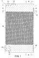
- FIG. 9 is a schematic structural view of the heat exchange plate according to the second embodiment of the present invention
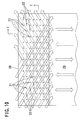
- FIG. 10 is a view schematically illustrating a flowing state of the fluids on the opposite surfaces of the fluid guiding portion of the heat exchange plate according to the second embodiment of the present invention
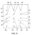
- FIG. 11 is an enlarged view of a portion "E" as shown in FIG. 10
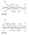
- FIG. 12 is a cross-sectional view cut along the line XII-XII in FIG. 11
- FIG. 13 is a cross-sectional view cut along the line XIII-XIII in FIG. 11.
- the heat exchange plate 2 according to the second embodiment of the present invention is identical to that of the first embodiment of the present invention in that the plate is formed of a metallic plate having a rectangular shape and provided with a fluid guiding portion 20 having a sub-pattern of irregularity (i.e., the second sub-pattern of irregularity), which includes a plurality of projections 21 and a plurality of recesses 22.
- the plate 2 is different from that of the first embodiment of the present invention in that predetermined opposite regions of each of the upper and lower sides of the plate serve as the inlet and outlet portions in use of the assembled unit for the heat exchanger, respectively, and the projections 21 and the recesses 22 are aligned linearly and obliquely in accordance with the positions of the inlet and outlet portions.
- the fluid guiding portions 20 are provided in the vicinity of the respective short sides of the heat exchange plate 2 and have a longitudinal length so as to correspond to the inlet and outlet portions for the heat exchange fluids in the unit for the heat exchanger, into which the plates are assembled, and a lateral length extending over the entire short side of the plate.
- the projections 21 and the recesses 22 are aligned along straight lines that directly extend from the inlet and outlet portions to the edge of the main heat transfer section 26 in oblique directions relative to the respective edges of the rectangular plate at the predetermined intervals.
- Each of the projections 21 is identical to the projection 11 of the first embodiment of the present invention in that the projection 21 includes a top portion 21a provided in the form of a circular flat section and an outer peripheral surface, which has a curved shape so as to continuously extend from the top portion 21a and broaden toward a lower side.
- the projections 21 of the second embodiment of the present invention are different from the projections 11 of the first embodiment of the present invention in that the projections 21 are aligned on the surface of the plate along straight lines that are located at the predetermined intervals so as to be oblique relative to the edge of the plate.
- Each of the recesses 22 includes a bottom portion 22a and an inner peripheral surface, which has a curved shape so as to continuously extend from the outer peripheral surface of the surrounding projection 21.
- the recess 22 is formed on the surface of the plate so as to dent in the opposite direction to the projecting direction of the projection 21.
- the recesses 12 are aligned along oblique straight lines relative to the edge of the plate in the same manner as the above-mentioned projections 21, so that each of the recesses 22 is placed in a central position of the smallest rhomboid area defined by four projections 21.
- the projections 21 and the recesses 22 are aligned at regular intervals with the result that the outer peripheral surfaces of the projections 21 and the inner peripheral surfaces of the recesses 22 provide a substantially sinusoidal wave in cross-sections of the projections 21 and the recesses 22 in the aligning direction thereof.
- Transitional curved sections 23 are provided in a central position between the adjacent two projections 21 and in a central position between the adjacent two recesses 22 so as to smoothly connect the curved surfaces of the projections 21 and the recesses 22.
- the plate is provided with the second sub-pattern of irregularity in which the entire surface has a smoothly continuous curved surface over the fluid guiding portion 20 including regions between the projections 21 and the recesses 22, in the same manner as the first embodiment of the present invention. Therefore, it is possible to disperse force applied to the plate, enhance strength thereof to cope with high pressure of the fluid and improve formability of the plate.
- the recesses 22 provide on the other (i.e., lower) surface of the plate with the same configuration as the projections 21 and the projections 21 provide on the surface of the plate with the same configuration as the recesses 22, so as to provide on the opposite surfaces of the plate with the same second sub-pattern of irregularity.
- the above-described heat exchange plate 2 is placed on the other heat exchange plate having the same structure so that they face each other on the same side and the top portions 21a of the projections 21 of the former plate in the fluid guiding portion 20 come into contact with the corresponding top portions 21a of the projections 21 of the latter plate and top portions of projections (not shown) of the former plate, which forms the first sub-pattern of irregularity, in the main heat transfer section 26 come into contact with the corresponding top portions of the projections of the latter plate, to form a combined unit, and then the thus formed combined unit is combined to the other combined units in the same manner as the first embodiment of the present invention, to form a heat exchanger that has gaps, i.e., passages.
- the corresponding outer peripheral surfaces of the projections 21 of these plates 2, excluding the contacting top portions 21a face each other with a predetermined distance kept therebetween
- the corresponding transition curved portions 23 of these plates 2 face each other with a predetermined distance kept therebetween
- the corresponding recesses 22 having a smaller height than the transition curved portions 23 face each other with a predetermined distance kept therebetween.
- Gaps formed between the corresponding outer peripheral surfaces of the projections 22 communicate with gaps formed between the corresponding recesses 22 to form straight passages in an oblique direction.
- the adjacent passages are aligned so as to intersect each other to communicate with each other (see FIGS. 12 and 13).
- the same pattern of irregularity provides the same structure with the result that the passage extends linearly, while expanding and reducing in a repeated manner, and such a passage intersects the other passages so as to communicate therewith, thus providing a braided passage structure (see FIGS. 12 and 13) in the same manner as described above.
- the main passages i.e., the gaps each of which is defined by the alternating corresponding recesses 22 and transition curved portions 23, are kept horizontally or vertically.
- the plate is provided on the lower surface side with the reverse pattern of irregularity to the upper surface side so that the projections on the upper surface of the plate correspond to the recesses on the lower surface of the plate on the basis of the same pattern of irregularity.
- These plates are placed one upon another on the same side, resulting in deviation of position of the projections and recesses by a half length of the distance between them. Except for this matter, the same conditions are kept for each of the gaps between the plates.
- the respective heat exchange fluids are introduced in an oblique direction from fluid supply sections 61, 71 into the unit through the openings serving as the inlet portions and discharged from the other openings serving as the outlet portions to fluid recover sections 62, 72 so that the heat exchange fluids alternately flow in the respective gaps between the plates based on a counter-flowing system.
- each heat exchange plate 2 In the upper fluid guiding portion 20 of each heat exchange plate 2, one of the heat exchange fluids is introduced obliquely from the upper corner, which is defined by the upper lateral side and the side longitudinal side of the plate, into the gap 24 formed on one side of the plate, to flow therein.
- the other heat exchange fluid as flowing in the other gap 25, which is placed oppositely to the above-mentioned gap 24 relative to the heat exchange plate 2, is discharged outside from the upper corner that is placed oppositely to the above-mentioned upper corner.
- the heat exchange fluid which has flown in the gap 24, is discharged outside from the lower corner, which is placed oppositely to the above-mentioned introducing position.
- the other heat exchange fluid is obliquely introduced into the other gap 25 from the inlet portion, which is placed oppositely to the above-mentioned outlet portion, to flow therein.
- the heat exchange fluid first flows obliquely in the upper region of the gap 24 with its introducing power into the fluid guiding portion 20 and then flows mainly in the initial traveling direction, while repeating divergence and confluence at intersections of the passages, to reach smoothly and uniformly the edge of the main heat transfer sections 26 (see arrows indicated in solid lines in FIG. 10).
- the heat exchange fluid can uniformly reach the edge of the main heat transfer sections 26 to cause the heat exchange fluid to flow to every areas on the opposite surfaces of the main heat transfer section 26 of the heat transfer plate 2 in this manner.
- this fluid flowing horizontally in a uniformly distributed amount travels from the edge of the main heat transfer section 26 to enter the fluid guiding portion 20, flows obliquely along the passages defined by the projections 21 and the recesses 22, and then reaches the outlet portion, while repeating confluence and divergence at intersections of the passages. More specifically, the heat exchange fluid flows obliquely and reach smoothly the opening serving as the outlet portion. It is therefore possible to receive uniformly the heat exchange fluid from the edge of the main heat transfer section 26 and then cause it to flow smoothly, thus avoiding a problem of adverse effect of irregular flow of the fluid in the main heat transfer section 26 due to clogging of the heat exchange fluid.
- the passages which mainly include the recesses 22 provided on the bask side of the projections 21, and the transitional curved sections 23, extend vertically and horizontally in the same manner as the gap 24.
- a portion of the gap 25, which corresponds to the inlet portion of the gap 24, serves as the outlet portion
- a portion of the gap, which corresponds to the outlet portion of the gap 24, serves as the inlet portion.
- the other heat exchange fluid in the gap 25 has the similar flowing behavior to the heat exchange fluid in the gap 24. More specifically, the other heat exchange fluid flows obliquely at the fluid guiding portion 20 on the inlet portion side to reach smoothly and uniformly the edge of the main heat transfer section 26. The other heat exchange fluid travels from the edge of the main heat transfer section 26 through the obliquely extending passages in the fluid guiding portion 20 on the outlet side to the outlet portion to be discharged outside (see arrows indicated in broken lines in FIG. 10).
- the respective heat exchange fluids can pass through the gaps 24, 25 in the fluid guiding portion 20 toward the main heat transfer section 26. Accordingly, the two kinds of heat exchange fluids can spread into every corner of the main heat transfer sections 26 to facilitate heat transfer between the plate and the fluid, thus improving the heat exchange performance in the same manner as the first embodiment of the present invention.
- the general heat exchange performance of the plates can be improved by the heat exchange at the fluid guiding portions 20.
- the projections 21 and the recesses 22 are aligned linearly in the oblique direction between the inlet and outlet portions and the main heat transfer section 26.
- the plurality of plates having the above-mentioned structure are placed one upon another and combined together to form an assembly unit for a heat exchanger, there are formed between the plates, the passages that extend directly and linearly from the inlet and outlet portions to the main heat transfer section 26.
- the heat exchange fluid flows in the passages in the fluid guiding portions 20 of the plates, the fluid smoothly and obliquely passes through the fluid guiding portions 20 to be introduced uniformly into the main heat transfer section 26 or discharged rapidly from the outlet portion.
- the heat exchange fluid flows uniformly from the side of the fluid guiding portion 20 into a boundary position relative to the main heat transfer section 26. Accordingly, the heat exchange fluid can flow uniformly to every corner of the main heat transfer section 26 to cause almost all area of the plate to serve as an effective heat transfer member. It is therefore possible to ensure an appropriate heat transfer between the plate and the heat exchange fluid to increase an amount of heat transfer, thus performing an effective heat exchange between the heat exchange fluids and providing a higher capacity heat exchanger.
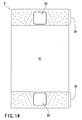
- FIG. 14 is a schematic structural view of the heat exchange plate according to the third embodiment of the present invention
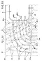
- FIG. 15 is a view schematically illustrating a flowing state of the fluids on the opposite surfaces of the fluid guiding portion of the heat exchange plate according to the third embodiment of the present invention
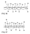
- FIG. 16 is a cross-sectional view cut along the line XVI-XVI in FIG. 15
- FIG. 17 is a cross-sectional view cut along the line XVII-XVII in FIG. 15
- FIG. 18 is a cross-sectional view cut along the line XVIII-XVIII in FIG. 15
- FIG. 19 is a cross-sectional view cut along the line XIX-XIX in FIG. 15.
- the heat exchange plate 3 according to the third embodiment of the present invention is identical to that of the first embodiment of the present invention in that the plate is formed of a metallic plate having a rectangular shape and provided with a fluid guiding portion 30 having a sub-pattern of irregularity (i.e., the second sub-pattern of irregularity), which includes a plurality of projections 31 and a plurality of recesses 32.
- the plate 3 is different from that of the first embodiment of the present invention in that the plate has openings 50 formed on the opposite sides of the plate in the longitudinal direction thereof, and each of the openings 50 is surrounded with a fluid guiding portion 30 in which projections 31 and recesses 32 are aligned along curved lines extending from a periphery of the opening 50 to an edge of a main heat transfer section 37.
- the above-mentioned fluid guiding portion 30, which is provided on each of the opposite sides of the heat exchange plate 3 having a rectangular shape in the longitudinal direction, i.e., on each of the short sides of the plate, has an area that extends in the longitudinal direction of the heat exchange plate 3 by a predetermined distance, which is longer than the length of the opening 50 and extends in the lateral direction of the plate over the whole lateral length thereof.
- the projections 31 and the recesses 32 are provided on the opposite sides of the fluid guiding portion 30, between which the opening 50 is formed, so as to be symmetrical to each other relative to the center of the opening 50.
- the projections 31 and the recesses 32 are aligned along curved lines extending from the opening 50 to the edge of the main heat transfer section 37.
- Each of the projections 31 is identical to the projection of the first embodiment of the present invention in that the projection 31 includes a top portion 31a provided in the form of a circular flat section and an outer peripheral surface, which has a curved shape so as to continuously extend from the top portion 31a and broaden toward a lower side.
- the projections 31 of the third embodiment of the present invention are different from the projections 11 of the first embodiment of the present invention in that they are aligned along the curved lines, which extend from the edge of the opening 50 to the edge of the main heat transfer section 37, so as to be apart from each other.
- Each of the recesses 32 includes, at positions in which the projections 31 are aligned along the curved lines in the fluid guiding portion 30, a bottom portion 32a and an inner peripheral surface, which has a curved shape so as to continuously extend from the outer peripheral surface of the surrounding projection 31.
- the recess 32 is formed on the surface of the plate so as to dent in the opposite direction to the projecting direction of the projection 31.
- the recesses 32 are aligned along the curved lines, which extend from the edge of the opening 50 to the edge of the main heat transfer section 37, in the same manner as the above-mentioned projections 31, but the recesses 32 are provided in the different irregular pattern from the projections 31.
- the projections 31 and the recesses 32 are aligned so as to provide the respective continuous cross-sections along the curved lines.
- Transitional curved sections 33, 34 are provided in a central position between the adjacent two projections 31 and in a central position between the adjacent two recesses 32 so as to smoothly connect the curved surfaces of the projections 31 and the recesses 32.
- the transitional curved section 33 for the adjacent two projections 31 is different in shape from the transitional curved section 34 for the adjacent two recesses 32.
- the plate is provided with the second sub-pattern of irregularity in which the entire surface has a smoothly continuous curved surface over the fluid guiding portion 30 including regions between the projections 31 and the recesses 32, in this manner. Therefore, it is possible to disperse force applied to the plate, enhance strength thereof to cope with high pressure of the fluid and improve formability of the plate.
- the recesses 32 provide on the other (i.e., lower) surface of the plate with the same configuration as the projections 31 so as to form the projections 35 on the other surface thereof and the projections 31 provide on the surface of the plate with the same configuration as the recesses 32 so as to form the recesses 36 on the other surface thereof.
- the aligned projections 31 and the aligned recesses 32 are not common in regularity to each other and have an inversed relationship of the opposite surfaces of the plate, so as not to provide on the opposite surfaces of the plate with the same second sub-pattern of irregularity in the same manner as the first and second embodiments of the present invention.
- the above-described heat exchange plate 3 is placed on the other heat exchange plate having the same structure so that they face each other on the same side and the top portions 31a of the projections 31 of the former plate in the fluid guiding portion 30 come into contact with the corresponding top portions 31a of the projections 31 of the latter plate and top portions of projections (not shown) of the former plate, which forms the first sub-pattern of irregularity, in the main heat transfer section 37 come into contact with the corresponding top portions of the projections of the latter plate, to form a combined unit, and then the thus formed combined unit is combined to the other combined units in the same manner as the first embodiment of the present invention, to form a heat exchanger that has gaps, i.e., passages.
- the corresponding outer peripheral surfaces of the projections 31 of these plates 3, excluding the contacting top portions 31a face each other with a predetermined distance kept therebetween
- the corresponding transition curved portions 33 of these plates 3 face each other with a predetermined distance kept therebetween
- the corresponding recesses 32 having a smaller height than the transition curved portions 33 face each other with a predetermined distance kept therebetween.
- Gaps formed between the corresponding outer peripheral surfaces of the projections 32 communicate with gaps formed between the corresponding recesses 32 to form curved passages in the curved lines along which the projections 31 and the recesses 32 are aligned.
- the adjacent passages are aligned so as to intersect each other to communicate with each other (see FIGS. 16 to 19).
- the projections 35 and the recesses 36 in the fluid guiding portion 30 do not provide on the opposite surfaces of the plate with the same second sub-pattern of irregularity.
- the passage including the gaps, which are formed between the outer peripheries of the projections 35 and the recesses, as well as between the transitional curved sections 34 so as to communicate with each other is quite different from the passage formed in the gap 38.
- the recesses 36 and the transitional curved sections 34 are aligned in a vertical direction or an oblique direction so as to provide passages extending linearly in the vertical direction or a direction with a slightly inclined angle therefrom.
- the heat exchanger that is composed of the heat exchange plates 3 according to the embodiment of the present invention.
- the plate has the opening 50 serving as the inlet portion through which one of the heat exchange fluids is introduced into the gap 38, and the other opening 50 serving as the outlet portion from which the above-mentioned heat exchange fluid is discharged.
- additional openings are provided on the upper and lower sides of the unit so as to communicate with the gap 39.
- the other heat exchange fluid is introduced vertically from the additional opening serving as the inlet portion and the above-mentioned other heat exchange fluid is discharged from the other additional opening serving as the outlet portion so that the heat exchange fluids alternately flow in the respective gaps between the plates based on a counter-flowing system.
- each heat exchange plate 3 In the upper fluid guiding portion 30 of each heat exchange plate 3, one of the heat exchange fluids is introduced from the opening 50 in the fluid guiding portion 30 to flow therein.
- the other heat exchange fluid as flowing in the other gap 39 which is placed oppositely to the above-mentioned gap 38 relative to the heat exchange plate 3, is discharged outside from the upper side of the unit.
- the projections 31 and the recesses 32 aligned along the curved lines so as to form a plurality of passages in which one of the heat exchange fluids flows.
- a plurality of passages is provided so as to extend linearly in the vertical direction or an oblique direction in accordance with the arrangement of the projections 35 and the recesses 36 and intersect each other.
- the heat exchange fluid which has flown in the gap 38, is discharged outside from the other opening 50.
- the other heat exchange fluid is vertically introduced into the other gap 39 from the inlet portion, which is placed oppositely to the above-mentioned outlet portion, to flow therein.
- the heat exchange fluid is first spread out from the opening 50 in the gap 38 with its introducing power into the fluid guiding portion 30, and a part of the fluid directly flows to the main heat transfer section 37 below the opening 50, but a remaining major part thereof flows along the curved lines along which the projections 31 and the recesses 32 are aligned, while repeating divergence and confluence at intersections of the passages, to reach smoothly and uniformly the edge of the main heat transfer sections 37 (see arrows indicated in solid lines in FIG. 15).
- the heat exchange fluid can uniformly reach the edge of the main heat transfer sections 37 to cause the heat exchange fluid to flow to every areas on the opposite surfaces of the main heat transfer section 37 of the heat transfer plate 3 in this manner.
- this fluid flowing horizontally in a uniformly distributed amount travels from the edge of the main heat transfer section 37 to enter the fluid guiding portion 30, and a part of the fluid directly flows and come into the opening 50, which is placed below the main heat transfer section 37, but a remaining major part thereof flows along the curved lines along which the projections 31 and the recesses 32 are aligned, and come into the opening 50, while repeating divergence and confluence at intersections of the passages. More specifically, the heat exchange fluid flows in the curved passages and reach smoothly the opening 50 serving as the outlet portion. It is therefore possible to receive uniformly the heat exchange fluid from the edge of the main heat transfer section 37 and then cause it to flow smoothly, thus avoiding a problem of adverse effect of irregular flow of the fluid in the main heat transfer section 37 due to clogging of the heat exchange fluid.
- the passages which mainly include the recesses 32 provided on the bask side of the projections 31, and the transitional curved sections 33, extend vertically or in a direction with a slightly inclined angle. Consequently, the inlet side of the gap 38 serves as the outlet side of the gap 39 and the outlet side of the gap 38 serves as the inlet side of the gap 39, in the same manner as the first and second embodiments of the present invention.
- the other heat exchange fluid in the gap 39 flows in the passages, which extend vertically or in a direction with s slightly inclined angle from the edge of the fluid guiding portion 30 on the inlet side thereof, to reach smoothly and uniformly the edge of the main heat transfer section 37.
- the other heat exchange fluid travels from the edge of the main heat transfer section 37 through the passages extending vertically or in the direction with the slightly inclined angle in the fluid guiding portion 30 on the outlet side to the outlet portion to be discharged outside (see arrows indicated in broken lines in FIG. 15).
- the respective heat exchange fluids can pass through the gaps 38, 39 in the fluid guiding portion 30 toward the main heat transfer section 37. Accordingly, the two kinds of heat exchange fluids can spread into every corner of the main heat transfer sections 37 to facilitate heat transfer between the plate and the fluid, thus improving the heat exchange performance in the same manner as the first embodiment of the present invention.
- the general heat exchange performance of the plates can be improved by the heat exchange at the fluid guiding portions 30.
- the projections 31 and the recesses 32 in the fluid guiding portion 30 are aligned along the curved lines extending from the opening 50 to the main heat transfer section 37 in accordance with the structure of the plate, which has the openings 50 serving as the inlet and outlet portions for the heat exchange fluid.
- the plurality of plates having the above-mentioned structure are placed one upon another and combined together to form an assembly unit for a heat exchanger, there are formed in the gaps 38, 39 between the plates, the passages that extend curvedly along the curved lines along which the projections 31 and the recesses 32 are aligned and communicate with each other.
- the heat exchange fluid which is in particularly introduced in the gap between the plates from the opening 50 on the inlet side, is introduced into the passages in the fluid guiding portions 30 of the plates through the opening 50 and discharged therefrom, the fluid can directly flow to come into the main heat transfer section 37 through the curved passages in the fluid guiding portion 30, thus making it possible to cause the heat exchange fluid to flow uniformly into every corner of the main heat transfer section 37, which includes portions of the main heat transfer section 37 that are apart from the opening 50, from the side of the fluid guiding portion 30. It is therefore possible to ensure an appropriate heat transfer between the plate and the heat exchange fluid, thus providing a higher capacity heat exchanger.
- the inlet and/or outlet portions for the other heat exchange fluid is provided in the predetermined region at the edge of the plate and at least part of the projections 31 formed on the basis of the curved arrangement provides the linear arrangement in the vicinity of the straight line connecting the inlet and/or outlet portions to the main heat transfer section 37.
- the corresponding recess portions 36 formed on the back side of the projections 31 on the second surface of the plate are aligned linearly to provide a main section for the passage for the fluid on the second surface of the plate.
- the heat exchange plate according to the above-described third embodiment of the present invention has a structure in which the projections 31 and the recesses 32 are aligned along the curved lines in view of the positions of the openings 50 serving as the inlet and outlet portions for the heat exchange fluid.
- the present invention is not limited only to such an embodiment. Even when the inlet and outlet portions for the heat exchange fluid are provided in the form of opening, the projections 31 and the recesses 32 may be aligned linearly. In addition, even when the inlet and outlet portions for the heat exchange fluid are provided in the vicinity of the edges of the plate, the projections 31 and the recesses 32 may be aligned along the curved lines.
- any desired structural features may be applied, except for providing the fluid guiding portion in accordance with the positions and characteristic features of the inlet and outlet portions for the heat exchange fluid and the main heat transfer section.
- the heat exchange plate of the present invention may have a desired shape in a peripheral portion and openings formed in desired positions so as to be capable of being used as a heat exchange plate for a heat exchanger in which a plurality of plates are directly connected to each other by welding or brazing the plates at their peripheries or diffusion bonding the plates at connection portions including the top portions of the projections thereof, or a plate-type heat exchanger in which a plurality of plates are placed one upon another, with gasket members placed therebetween, and subjected to a pressing process for imparting an external pressure to them to form a combined unit.
Landscapes
- Engineering & Computer Science (AREA)
- Physics & Mathematics (AREA)
- Thermal Sciences (AREA)
- Mechanical Engineering (AREA)
- General Engineering & Computer Science (AREA)
- Heat-Exchange Devices With Radiators And Conduit Assemblies (AREA)
Applications Claiming Priority (1)
| Application Number | Priority Date | Filing Date | Title |
|---|---|---|---|
| JP2005356957A JP2007162974A (ja) | 2005-12-09 | 2005-12-09 | 熱交換用プレート |
Publications (1)
| Publication Number | Publication Date |
|---|---|
| EP1813901A2 true EP1813901A2 (fr) | 2007-08-01 |
Family
ID=38002021
Family Applications (1)
| Application Number | Title | Priority Date | Filing Date |
|---|---|---|---|
| EP06024631A Withdrawn EP1813901A2 (fr) | 2005-12-09 | 2006-11-28 | Plaque d'échange de chaleur |
Country Status (6)
| Country | Link |
|---|---|
| US (1) | US20070151717A1 (fr) |
| EP (1) | EP1813901A2 (fr) |
| JP (1) | JP2007162974A (fr) |
| KR (1) | KR20070061448A (fr) |
| CN (1) | CN1979078A (fr) |
| TW (1) | TW200730789A (fr) |
Cited By (3)
| Publication number | Priority date | Publication date | Assignee | Title |
|---|---|---|---|---|
| EP2455694A2 (fr) * | 2010-11-19 | 2012-05-23 | Danfoss A/S | Échangeur de chaleur |
| CN110199169A (zh) * | 2017-01-13 | 2019-09-03 | 大金工业株式会社 | 水热交换器 |
| US10473403B2 (en) | 2010-11-19 | 2019-11-12 | Danfoss A/S | Heat exchanger |
Families Citing this family (4)
| Publication number | Priority date | Publication date | Assignee | Title |
|---|---|---|---|---|
| JPWO2010013608A1 (ja) * | 2008-07-29 | 2012-01-12 | 株式会社ササクラ | 蒸発器又は凝縮器として使用されるプレート型熱交換装置 |
| CN102730345B (zh) * | 2011-04-15 | 2014-11-26 | 宁波乐惠食品设备制造有限公司 | 夹套和夹套罐 |
| TWI546841B (zh) | 2014-12-10 | 2016-08-21 | 財團法人工業技術研究院 | 具有載台的電子顯微鏡 |
| FR3122728B1 (fr) * | 2021-05-06 | 2023-06-02 | Commissariat A L’Energie Atomique Et Aux Energies Alternatives | Module d’échangeur de chaleur à plaques à canaux intégrant au moins une zone d’alimentation et de distribution de fluide formée par des plots. |
Family Cites Families (7)
| Publication number | Priority date | Publication date | Assignee | Title |
|---|---|---|---|---|
| US1826344A (en) * | 1930-09-23 | 1931-10-06 | Res & Dev Corp | Heat exchange element |
| DE1601216B2 (de) * | 1967-11-03 | 1971-06-16 | Linde Ag, 6200 Wiesbaden | Blechtafel fuer platten waermetauscher mit einem stapel solcher blechtafeln |
| US3992835A (en) * | 1974-03-18 | 1976-11-23 | Saveker David R | Sinusoidal structural element |
| DE3415807A1 (de) * | 1984-04-27 | 1985-10-31 | Linde Ag, 6200 Wiesbaden | Waermetauscher |
| US5287918A (en) * | 1990-06-06 | 1994-02-22 | Rolls-Royce Plc | Heat exchangers |
| FR2685462B1 (fr) * | 1991-12-23 | 1999-02-05 | Andre Peze | Echangeur de chaleur a plaques soudees et procede de fabrication de modules de plaques permettant l'obtention de tels echangeurs. |
| FR2754595B1 (fr) * | 1996-10-11 | 1999-01-08 | Ziemann Secathen | Echangeur de chaleur, et faisceau d'echange de chaleur, ainsi que procedes de soudage et de realisation s'y rapportant |
-
2005
- 2005-12-09 JP JP2005356957A patent/JP2007162974A/ja active Pending
-
2006
- 2006-11-28 EP EP06024631A patent/EP1813901A2/fr not_active Withdrawn
- 2006-12-04 US US11/607,884 patent/US20070151717A1/en not_active Abandoned
- 2006-12-04 TW TW095144916A patent/TW200730789A/zh unknown
- 2006-12-08 CN CNA2006101656121A patent/CN1979078A/zh active Pending
- 2006-12-08 KR KR1020060124759A patent/KR20070061448A/ko not_active Withdrawn
Cited By (3)
| Publication number | Priority date | Publication date | Assignee | Title |
|---|---|---|---|---|
| EP2455694A2 (fr) * | 2010-11-19 | 2012-05-23 | Danfoss A/S | Échangeur de chaleur |
| US10473403B2 (en) | 2010-11-19 | 2019-11-12 | Danfoss A/S | Heat exchanger |
| CN110199169A (zh) * | 2017-01-13 | 2019-09-03 | 大金工业株式会社 | 水热交换器 |
Also Published As
| Publication number | Publication date |
|---|---|
| CN1979078A (zh) | 2007-06-13 |
| US20070151717A1 (en) | 2007-07-05 |
| TW200730789A (en) | 2007-08-16 |
| KR20070061448A (ko) | 2007-06-13 |
| JP2007162974A (ja) | 2007-06-28 |
Similar Documents
| Publication | Publication Date | Title |
|---|---|---|
| KR101445474B1 (ko) | 열교환판과 판형 열교환기 | |
| JP6163190B2 (ja) | 熱交換器 | |
| JP4584524B2 (ja) | 熱伝達プレートおよびプレート型熱交換器に用いるプレート充填体 | |
| CN103791757B (zh) | 传热板和包括这种传热板的板式热交换器 | |
| JP5872859B2 (ja) | 熱交換器 | |
| US20060185835A1 (en) | Heat exchange plate | |
| JP4584976B2 (ja) | 熱交換プレートおよびプレートパッケージ | |
| CN103528419B (zh) | 用于热交换器的板、热交换器和包括热交换器的空气冷却器 | |
| US8091619B2 (en) | Heat exchanger with indentation pattern | |
| CN110537069B (zh) | 热传递板和包括多个此类热传递板的热交换器 | |
| EP2068108A1 (fr) | Échangeur de chaleur et son procédé de fabrication | |
| JP2020176828A (ja) | 伝熱プレートおよび複数のかかる伝熱プレートを備えるプレート熱交換器 | |
| CN101346597A (zh) | 用于在口区域中具有均匀负载分配的板式换热器的传热板 | |
| KR20140009220A (ko) | 플레이트형 열 교환기와 플레이트형 열 교환기를 제조하는 방법 | |
| EP1813901A2 (fr) | Plaque d'échange de chaleur | |
| EP1739379A2 (fr) | Echangeur de chaleur | |
| EP1553372A2 (fr) | Plaque d'échangeur de chaleur et unité d'échange de chaleur | |
| JP2004184075A (ja) | 伝熱プレート及びプレート式熱交換器 | |
| EP1684044A2 (fr) | Plaque d'échangeur de chaleur | |
| CN112146484B (zh) | 板式换热器 | |
| US20110180247A1 (en) | Heat exchanger | |
| JP3146246B1 (ja) | プレート式熱交換器及びその溶接方法 | |
| EP1722183A2 (fr) | Unité d'échange de chaleur | |
| US12498183B2 (en) | Plate stacking type heat exchanger | |
| KR20050073424A (ko) | 열교환용 플레이트 및 열교환 유닛 |
Legal Events
| Date | Code | Title | Description |
|---|---|---|---|
| PUAI | Public reference made under article 153(3) epc to a published international application that has entered the european phase |
Free format text: ORIGINAL CODE: 0009012 |
|
| AK | Designated contracting states |
Kind code of ref document: A2 Designated state(s): AT BE BG CH CY CZ DE DK EE ES FI FR GB GR HU IE IS IT LI LT LU LV MC NL PL PT RO SE SI SK TR |
|
| AX | Request for extension of the european patent |
Extension state: AL BA HR MK YU |
|
| STAA | Information on the status of an ep patent application or granted ep patent |
Free format text: STATUS: THE APPLICATION IS DEEMED TO BE WITHDRAWN |
|
| 18D | Application deemed to be withdrawn |
Effective date: 20090603 |