EP2068108A1 - Échangeur de chaleur et son procédé de fabrication - Google Patents
Échangeur de chaleur et son procédé de fabrication Download PDFInfo
- Publication number
- EP2068108A1 EP2068108A1 EP07828428A EP07828428A EP2068108A1 EP 2068108 A1 EP2068108 A1 EP 2068108A1 EP 07828428 A EP07828428 A EP 07828428A EP 07828428 A EP07828428 A EP 07828428A EP 2068108 A1 EP2068108 A1 EP 2068108A1
- Authority
- EP
- European Patent Office
- Prior art keywords
- fluid
- heat exchanger
- fin
- fins
- region
- Prior art date
- Legal status (The legal status is an assumption and is not a legal conclusion. Google has not performed a legal analysis and makes no representation as to the accuracy of the status listed.)
- Withdrawn
Links
Images













Classifications
-
- F—MECHANICAL ENGINEERING; LIGHTING; HEATING; WEAPONS; BLASTING
- F28—HEAT EXCHANGE IN GENERAL
- F28D—HEAT-EXCHANGE APPARATUS, NOT PROVIDED FOR IN ANOTHER SUBCLASS, IN WHICH THE HEAT-EXCHANGE MEDIA DO NOT COME INTO DIRECT CONTACT
- F28D9/00—Heat-exchange apparatus having stationary plate-like or laminated conduit assemblies for both heat-exchange media, the media being in contact with different sides of a conduit wall
- F28D9/0031—Heat-exchange apparatus having stationary plate-like or laminated conduit assemblies for both heat-exchange media, the media being in contact with different sides of a conduit wall the conduits for one heat-exchange medium being formed by paired plates touching each other
- F28D9/0043—Heat-exchange apparatus having stationary plate-like or laminated conduit assemblies for both heat-exchange media, the media being in contact with different sides of a conduit wall the conduits for one heat-exchange medium being formed by paired plates touching each other the plates having openings therein for circulation of at least one heat-exchange medium from one conduit to another
- F28D9/005—Heat-exchange apparatus having stationary plate-like or laminated conduit assemblies for both heat-exchange media, the media being in contact with different sides of a conduit wall the conduits for one heat-exchange medium being formed by paired plates touching each other the plates having openings therein for circulation of at least one heat-exchange medium from one conduit to another the plates having openings therein for both heat-exchange media
-
- F—MECHANICAL ENGINEERING; LIGHTING; HEATING; WEAPONS; BLASTING
- F28—HEAT EXCHANGE IN GENERAL
- F28F—DETAILS OF HEAT-EXCHANGE AND HEAT-TRANSFER APPARATUS, OF GENERAL APPLICATION
- F28F3/00—Plate-like or laminated elements; Assemblies of plate-like or laminated elements
- F28F3/02—Elements or assemblies thereof with means for increasing heat-transfer area, e.g. with fins, with recesses, with corrugations
- F28F3/025—Elements or assemblies thereof with means for increasing heat-transfer area, e.g. with fins, with recesses, with corrugations the means being corrugated, plate-like elements
- F28F3/027—Elements or assemblies thereof with means for increasing heat-transfer area, e.g. with fins, with recesses, with corrugations the means being corrugated, plate-like elements with openings, e.g. louvered corrugated fins; Assemblies of corrugated strips
-
- F—MECHANICAL ENGINEERING; LIGHTING; HEATING; WEAPONS; BLASTING
- F25—REFRIGERATION OR COOLING; COMBINED HEATING AND REFRIGERATION SYSTEMS; HEAT PUMP SYSTEMS; MANUFACTURE OR STORAGE OF ICE; LIQUEFACTION SOLIDIFICATION OF GASES
- F25B—REFRIGERATION MACHINES, PLANTS OR SYSTEMS; COMBINED HEATING AND REFRIGERATION SYSTEMS; HEAT PUMP SYSTEMS
- F25B39/00—Evaporators; Condensers
-
- Y—GENERAL TAGGING OF NEW TECHNOLOGICAL DEVELOPMENTS; GENERAL TAGGING OF CROSS-SECTIONAL TECHNOLOGIES SPANNING OVER SEVERAL SECTIONS OF THE IPC; TECHNICAL SUBJECTS COVERED BY FORMER USPC CROSS-REFERENCE ART COLLECTIONS [XRACs] AND DIGESTS
- Y10—TECHNICAL SUBJECTS COVERED BY FORMER USPC
- Y10T—TECHNICAL SUBJECTS COVERED BY FORMER US CLASSIFICATION
- Y10T29/00—Metal working
- Y10T29/49—Method of mechanical manufacture
- Y10T29/4935—Heat exchanger or boiler making
- Y10T29/49377—Tube with heat transfer means
- Y10T29/49378—Finned tube
Definitions
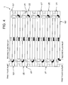
- the fins 5 have a constitution in which the sides of one set of facing fins have a height dimension substantially equal to that of the peripheral wall portion 3 of the flat plate 1 or 2 and in which the sides of the other set of facing fins have a width (an inner width) substantially equal to that of the flat plate 1 or 2.
- the fins are successively received between the guide plates 10 and 11 arranged in the flat plates 1, 2 on both the ends so that in a state in which the fins are received in the flat plate 1, one of the sides of the set of fins 5 abuts on the bottom of the flat plate 1 or 2, the other side is positioned in the upper surface of the container, and the side of the other set abuts on the peripheral wall portion 3.
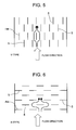
- the plurality of fins 5 received in the flat plates 1, 2 of the respective units U1, U2 have a constitution in which the fins are arranged in parallel with the flow direction of the fluid from the inflow port 15 to the outflow port 16 as shown in FIG. 5 (hereinafter referred to as the V-type unit) or a constitution in which the fins 5 are arranged so as to cross the flow direction of the fluid from the inflow port 15 to the outflow port 16 at right angles as shown in FIG. 6 (hereinafter referred to as the H-type unit), and the fins are laminated as described above to constitute the heat exchanger.
- the V-type unit a constitution in which the fins are arranged in parallel with the flow direction of the fluid from the inflow port 15 to the outflow port 16 as shown in FIG. 5
- the H-type unit a constitution in which the fins 5 are arranged so as to cross the flow direction of the fluid from the inflow port 15 to the outflow port 16 at right angles as shown in FIG. 6
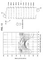
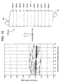
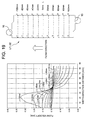
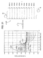
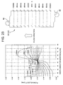
- 0% of the abscissa indicates the heat exchanger (i.e., a case where the heat exchanger is constituted of the V-type unit) constituted of the unit in which all the fins 5 are constituted of the fin parallel region V, and 100% indicates the heat exchanger (i.e., a case where the heat exchanger is constituted of the H-type unit) constituted of the unit in which all the fins 5 are constituted of the fin orthogonal region H).
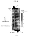
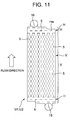
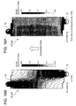
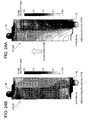
- the ratio between the fin orthogonal region H and the fin parallel region V when the difference between the maximum flow velocity and the minimum flow velocity of the fluid in the plane crossing the flow direction of the fluid at right angles is integrated with respect to the flow direction of the fluid and the ratio of the fin orthogonal region H with respect to the whole is increased, the inflection point where the tilt of the integrated value becomes moderate is regarded as the maximum value, and the ratio of each fin orthogonal region H is set within a range of a value larger than zero to a value of the maximum value or less. In consequence, it is possible to manufacture the heat exchanger capable of improving the non-uniform rate distribution and having a high performance with less pressure drop.
Landscapes
- Engineering & Computer Science (AREA)
- Physics & Mathematics (AREA)
- Thermal Sciences (AREA)
- Mechanical Engineering (AREA)
- General Engineering & Computer Science (AREA)
- Heat-Exchange Devices With Radiators And Conduit Assemblies (AREA)
- Fuel Cell (AREA)
Applications Claiming Priority (2)
| Application Number | Priority Date | Filing Date | Title |
|---|---|---|---|
| JP2006264940A JP4818044B2 (ja) | 2006-09-28 | 2006-09-28 | 熱交換器の製造方法 |
| PCT/JP2007/068682 WO2008038666A1 (fr) | 2006-09-28 | 2007-09-26 | Échangeur de chaleur et son procédé de fabrication |
Publications (2)
| Publication Number | Publication Date |
|---|---|
| EP2068108A1 true EP2068108A1 (fr) | 2009-06-10 |
| EP2068108A4 EP2068108A4 (fr) | 2013-04-03 |
Family
ID=39230102
Family Applications (1)
| Application Number | Title | Priority Date | Filing Date |
|---|---|---|---|
| EP07828428A Withdrawn EP2068108A4 (fr) | 2006-09-28 | 2007-09-26 | Échangeur de chaleur et son procédé de fabrication |
Country Status (5)
| Country | Link |
|---|---|
| US (1) | US20100025025A1 (fr) |
| EP (1) | EP2068108A4 (fr) |
| JP (1) | JP4818044B2 (fr) |
| CN (1) | CN101517347B (fr) |
| WO (1) | WO2008038666A1 (fr) |
Families Citing this family (16)
| Publication number | Priority date | Publication date | Assignee | Title |
|---|---|---|---|---|
| US20100059215A1 (en) * | 2008-09-11 | 2010-03-11 | Proliance International Inc. | Plate type oil cooler |
| US20110284195A1 (en) * | 2010-05-20 | 2011-11-24 | Delphi Technologies, Inc. | Fabricated tube for an evaporator |
| CN102032830B (zh) * | 2010-11-27 | 2012-12-19 | 浙江银轮机械股份有限公司 | 一种用于板翅式换热器的混合型锯齿形错列翅片 |
| TWI493144B (zh) * | 2012-09-07 | 2015-07-21 | Ind Tech Res Inst | 熱交換循環系統 |
| US10962307B2 (en) | 2013-02-27 | 2021-03-30 | Denso Corporation | Stacked heat exchanger |
| JP6160385B2 (ja) * | 2013-09-17 | 2017-07-12 | 株式会社デンソー | 積層型熱交換器 |
| JP6094261B2 (ja) * | 2013-02-27 | 2017-03-15 | 株式会社デンソー | 積層型熱交換器 |
| JP6091601B2 (ja) * | 2013-03-22 | 2017-03-08 | 三菱電機株式会社 | プレート式熱交換器及びそれを備えた冷凍サイクル装置 |
| JP6599121B2 (ja) * | 2015-04-13 | 2019-10-30 | 日野自動車株式会社 | 熱交換器及び廃熱回収装置 |
| JP6548324B2 (ja) * | 2015-06-30 | 2019-07-24 | 東京ラヂエーター製造株式会社 | 熱交換器のインナーフィン |
| JP2019095119A (ja) * | 2017-11-21 | 2019-06-20 | トヨタ自動車株式会社 | 熱交換装置 |
| CN109612311A (zh) * | 2019-01-17 | 2019-04-12 | 广东环葆嘉节能科技有限公司 | 一种换热组件及换热器 |
| WO2020245876A1 (fr) * | 2019-06-03 | 2020-12-10 | 三菱電機株式会社 | Échangeur de chaleur du type à plaques et dispositif de transfert de chaleur |
| IL301067B1 (en) | 2020-09-04 | 2026-01-01 | Clean Power Hydrogen Group Ltd | Heat converter |
| MX2024008679A (es) * | 2023-08-17 | 2025-03-07 | Danfoss As | Intercambiador de calor de placas |
| WO2026013587A1 (fr) * | 2024-07-10 | 2026-01-15 | Ufi Innovation Center S.R.L. | Échangeur de chaleur |
Family Cites Families (22)
| Publication number | Priority date | Publication date | Assignee | Title |
|---|---|---|---|---|
| DE1152432B (de) * | 1962-04-21 | 1963-08-08 | Linde Eismasch Ag | Platten-Kondensator-Verdampfer, insbesondere fuer Gas- und Luftzerleger |
| US3282334A (en) * | 1963-04-29 | 1966-11-01 | Trane Co | Heat exchanger |
| US3860065A (en) * | 1970-04-08 | 1975-01-14 | Trane Co | Distributor for plate type heat exchanger having side headers |
| JPS6218867Y2 (fr) * | 1981-03-20 | 1987-05-14 | ||
| FR2547898B1 (fr) * | 1983-06-24 | 1985-11-29 | Air Liquide | Procede et dispositif pour vaporiser un liquide par echange de chaleur avec un deuxieme fluide, et leur application a une installation de distillation d'air |
| US5122174A (en) * | 1991-03-01 | 1992-06-16 | Air Products And Chemicals, Inc. | Boiling process and a heat exchanger for use in the process |
| SE505225C2 (sv) * | 1993-02-19 | 1997-07-21 | Alfa Laval Thermal Ab | Plattvärmeväxlare och platta härför |
| CA2222716A1 (fr) * | 1996-03-30 | 1997-10-09 | Keith Thomas Symonds | Echangeur de chaleur a plaques presentant des zones de repartition |
| JPH09296989A (ja) * | 1996-05-02 | 1997-11-18 | Toyo Radiator Co Ltd | 熱交換器用フィンおよびその製造方法並びに熱交換器 |
| JP3054888U (ja) * | 1998-06-12 | 1998-12-18 | 石川島播磨重工業株式会社 | プレートフィン型熱交換器 |
| JP4592125B2 (ja) * | 1998-10-05 | 2010-12-01 | 大陽日酸株式会社 | 流下液膜式凝縮蒸発器 |
| FR2790546B1 (fr) * | 1999-03-01 | 2001-04-20 | Air Liquide | Echangeur de chaleur, applications a la vaporisation de liquide sous pression et appareil de distillation d'air equipe d'un tel echangeur |
| FR2807828B1 (fr) * | 2000-04-17 | 2002-07-12 | Nordon Cryogenie Snc | Ailette ondulee a decalage partiel pour echangeur de chaleur a plaques et echangeur de chaleur a plaques correspondant |
| DE10035939A1 (de) * | 2000-07-21 | 2002-02-07 | Bosch Gmbh Robert | Vorrichtung zur Wärmeübertragung |
| FR2819048B1 (fr) * | 2000-12-28 | 2005-08-19 | Air Liquide | Ailette ondulee pour echangeur de chaleur a plaques brasees et echangeur de chaleur correspondant |
| JP3605089B2 (ja) * | 2002-04-22 | 2004-12-22 | 東京ブレイズ株式会社 | チタン製プレート型熱交換器の製造方法 |
| US6793012B2 (en) * | 2002-05-07 | 2004-09-21 | Valeo, Inc | Heat exchanger |
| FR2848292B1 (fr) * | 2002-12-05 | 2005-03-04 | Packinox Sa | Plaque d'un echangeur thermique et echangeur thermique a plaques |
| US6948473B2 (en) * | 2003-02-04 | 2005-09-27 | Joseph Dale Udy | 4-cycle, rotary, electromagnetic, internal combustion engines |
| JP2006064345A (ja) * | 2004-08-30 | 2006-03-09 | T Rad Co Ltd | 伝熱フィン |
| JP2006125767A (ja) * | 2004-10-29 | 2006-05-18 | Tokyo Institute Of Technology | 熱交換器 |
| JP2006183945A (ja) * | 2004-12-28 | 2006-07-13 | Mahle Filter Systems Japan Corp | オイルクーラ |
-
2006
- 2006-09-28 JP JP2006264940A patent/JP4818044B2/ja not_active Expired - Fee Related
-
2007
- 2007-09-26 US US12/442,282 patent/US20100025025A1/en not_active Abandoned
- 2007-09-26 EP EP07828428A patent/EP2068108A4/fr not_active Withdrawn
- 2007-09-26 CN CN200780035045.0A patent/CN101517347B/zh not_active Expired - Fee Related
- 2007-09-26 WO PCT/JP2007/068682 patent/WO2008038666A1/fr not_active Ceased
Also Published As
| Publication number | Publication date |
|---|---|
| JP2008082650A (ja) | 2008-04-10 |
| CN101517347B (zh) | 2011-05-25 |
| WO2008038666A1 (fr) | 2008-04-03 |
| JP4818044B2 (ja) | 2011-11-16 |
| EP2068108A4 (fr) | 2013-04-03 |
| CN101517347A (zh) | 2009-08-26 |
| US20100025025A1 (en) | 2010-02-04 |
Similar Documents
| Publication | Publication Date | Title |
|---|---|---|
| EP2068108A1 (fr) | Échangeur de chaleur et son procédé de fabrication | |
| EP2410278B1 (fr) | Échangeur thermique de type à plaques et dispositif de conditionnement d'air et de réfrigération | |
| CN1299091C (zh) | 传热板、板组件和板式热交换器 | |
| EP3413003B1 (fr) | Plaque d'échange de chaleur, et échangeur de chaleur à plaques utilisant celle-ci | |
| KR102432036B1 (ko) | 열 전달 판 및 가스켓 | |
| EP1070928A1 (fr) | Echangeur thermique du type a plaques | |
| EP3484254B1 (fr) | Noyau de dissipateur de chaleur stratifié | |
| KR102217703B1 (ko) | 판형 열 교환기를 위한 열 교환 판 및 상기 열 교환 판을 구비한 판형 열 교환기 | |
| JP4584976B2 (ja) | 熱交換プレートおよびプレートパッケージ | |
| EP2865983A1 (fr) | Collecteur d'échangeur de chaleur et échangeur de chaleur le comportant | |
| US7055585B2 (en) | Layered evaporator for use in motor vehicle air conditioners or the like, layered heat exchanger for providing the evaporator, and refrigeration cycle system comprising the evaporator | |
| US6742577B2 (en) | Laminate type evaporator | |
| KR100819603B1 (ko) | 열 교환기 및 차량 에어컨용 증발기 | |
| EP3199903A1 (fr) | Échangeur de chaleur et procédé d'échange de chaleur | |
| US7121331B2 (en) | Heat exchanger | |
| AU2002234898A1 (en) | Heat exchanger | |
| CN113950605A (zh) | 热交换器 | |
| CN112146484B (zh) | 板式换热器 | |
| KR101401987B1 (ko) | 판형 열교환기 | |
| JP7587174B2 (ja) | 熱交換器及び熱交換器の製造方法 | |
| WO2025126862A1 (fr) | Échangeur de chaleur | |
| EP1813901A2 (fr) | Plaque d'échange de chaleur | |
| WO2017195588A1 (fr) | Échangeur de chaleur de type à empilage | |
| JPH0539992A (ja) | 熱交換器 | |
| JP2025167553A (ja) | 熱交換器 |
Legal Events
| Date | Code | Title | Description |
|---|---|---|---|
| PUAI | Public reference made under article 153(3) epc to a published international application that has entered the european phase |
Free format text: ORIGINAL CODE: 0009012 |
|
| 17P | Request for examination filed |
Effective date: 20090217 |
|
| AK | Designated contracting states |
Kind code of ref document: A1 Designated state(s): AT BE BG CH CY CZ DE DK EE ES FI FR GB GR HU IE IS IT LI LT LU LV MC MT NL PL PT RO SE SI SK TR |
|
| AX | Request for extension of the european patent |
Extension state: AL BA HR MK RS |
|
| DAX | Request for extension of the european patent (deleted) | ||
| A4 | Supplementary search report drawn up and despatched |
Effective date: 20130301 |
|
| RIC1 | Information provided on ipc code assigned before grant |
Ipc: F28D 9/02 20060101ALI20130225BHEP Ipc: F28F 1/40 20060101ALI20130225BHEP Ipc: F25B 1/00 20060101ALI20130225BHEP Ipc: F28F 3/08 20060101AFI20130225BHEP Ipc: F25B 39/00 20060101ALI20130225BHEP |
|
| STAA | Information on the status of an ep patent application or granted ep patent |
Free format text: STATUS: THE APPLICATION HAS BEEN WITHDRAWN |
|
| 18W | Application withdrawn |
Effective date: 20130906 |