EP1814170A2 - Actionneur piézo-electrique/électrostrictif - Google Patents
Actionneur piézo-electrique/électrostrictif Download PDFInfo
- Publication number
- EP1814170A2 EP1814170A2 EP06255108A EP06255108A EP1814170A2 EP 1814170 A2 EP1814170 A2 EP 1814170A2 EP 06255108 A EP06255108 A EP 06255108A EP 06255108 A EP06255108 A EP 06255108A EP 1814170 A2 EP1814170 A2 EP 1814170A2
- Authority
- EP
- European Patent Office
- Prior art keywords
- piezoelectric body
- internal electrode
- piezoelectric
- electrostrictive actuator
- electrode layers
- Prior art date
- Legal status (The legal status is an assumption and is not a legal conclusion. Google has not performed a legal analysis and makes no representation as to the accuracy of the status listed.)
- Withdrawn
Links
Images


Classifications
-
- H—ELECTRICITY
- H10—SEMICONDUCTOR DEVICES; ELECTRIC SOLID-STATE DEVICES NOT OTHERWISE PROVIDED FOR
- H10N—ELECTRIC SOLID-STATE DEVICES NOT OTHERWISE PROVIDED FOR
- H10N30/00—Piezoelectric or electrostrictive devices
- H10N30/50—Piezoelectric or electrostrictive devices having a stacked or multilayer structure
- H10N30/503—Piezoelectric or electrostrictive devices having a stacked or multilayer structure having a non-rectangular cross-section in a plane orthogonal to the stacking direction, e.g. polygonal or circular in top view
-
- H—ELECTRICITY
- H10—SEMICONDUCTOR DEVICES; ELECTRIC SOLID-STATE DEVICES NOT OTHERWISE PROVIDED FOR
- H10N—ELECTRIC SOLID-STATE DEVICES NOT OTHERWISE PROVIDED FOR
- H10N30/00—Piezoelectric or electrostrictive devices
- H10N30/80—Constructional details
- H10N30/87—Electrodes or interconnections, e.g. leads or terminals
- H10N30/871—Single-layered electrodes of multilayer piezoelectric or electrostrictive devices, e.g. internal electrodes
-
- H—ELECTRICITY
- H10—SEMICONDUCTOR DEVICES; ELECTRIC SOLID-STATE DEVICES NOT OTHERWISE PROVIDED FOR
- H10N—ELECTRIC SOLID-STATE DEVICES NOT OTHERWISE PROVIDED FOR
- H10N30/00—Piezoelectric or electrostrictive devices
- H10N30/80—Constructional details
- H10N30/87—Electrodes or interconnections, e.g. leads or terminals
- H10N30/872—Interconnections, e.g. connection electrodes of multilayer piezoelectric or electrostrictive devices
- H10N30/874—Interconnections, e.g. connection electrodes of multilayer piezoelectric or electrostrictive devices embedded within piezoelectric or electrostrictive material, e.g. via connections
Definitions
- the present invention relates to a piezoelectric/electrostrictive actuator utilizing expansion and contraction of a plurality of piezoelectric body layers that are substantially stacked on one another.
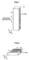
- a conventionally known piezoelectric/electrostrictive actuator 110 includes a generally rectangular parallelepipedic or cylindrical columnar piezoelectric body 111; a plurality of internal electrode layers 112 formed within the piezoelectric body 111 to be parallel with each other; and a pair of side-surface electrodes 113 formed on side surfaces of the piezoelectric body 111.
- Each of the internal electrode layers 112 is formed to be separated from one side-side surface electrode 113, extends to and along the outer circumference of the piezoelectric body 111, and is connected to the other side-surface electrode 113.
- piezoelectric/electrostrictive actuator 110 utilizes such expansion and contraction so as to produce force.
- a piezoelectric/electrostrictive actuator is applied to, for example, a fuel injection valve (see Japanese Patent Application Laid-Open (kokai) No. 2004-297042 ).
- the internal electrode layers 112 do not have a symmetric shape, as shown in FIG. 37, electric fields of directions other than the axial direction of the piezoelectric body 111 (Z-axis direction) are applied to the piezoelectric body 111 in the vicinity of end portions of the internal electrode layers 112. Therefore, the direction of expansion and contraction of the piezoelectric body 111 in the vicinity of end portions thereof differs from that at the central portion thereof, so that a large stress is generated at the end portions of the piezoelectric body 111. As a result, the service life of the piezoelectric/electrostrictive actuator 110 may be shortened.
- the present invention has been accomplished so as to solve the above-described problem, and one of objects of the present invention is to provide a piezoelectric/electrostrictive actuator which can reduce the maximum stress generated inside a piezoelectric body and which has a long service life.
- the present invention provides a piezoelectric/electrostrictive actuator comprising a piezoelectric body and a plurality of internal electrode layers formed in parallel within the piezoelectric body, in which a predetermined voltage is applied to the internal electrode layers so as to expand and contract the piezoelectric body.
- the internal electrode layers are disposed at a central portion of the piezoelectric body such that an active portion and an inactive portion are formed in the piezoelectric body, the active portion being the central portion of the piezoelectric body to which a voltage is applied so as to expand and contract the piezoelectric body, and the inactive portion being a peripheral portion of the piezoelectric body which surrounds the central portion of the piezoelectric body and in which no voltage is applied to the piezoelectric body and the piezoelectric body neither expands nor contracts.
- the internal electrode layers are formed such that the width of the inactive portion, which is the distance between the outer edge of the piezoelectric body and the active portion, is at least a single layer thickness of the piezoelectric body, which is the distance between a pair of internal electrode layers facing each other, and, in a cross section in which each internal electrode layer is formed, the inactive portion has an area equal to or less than 50% the area of the entire cross section.
- an inactive portion is formed over the entirety of a peripheral portion of the piezoelectric body which surrounds the central portion of the piezoelectric body serving as an active portion.
- the boundary between the active portion and the inactive portion is not exposed to the outer edge (side surface) of the piezoelectric body where stress concentration is likely to occur due to surface roughness, surface flaws, or the like, the maximum stress generated in the piezoelectric body is reduced. As a result, the service life of the piezoelectric/electrostrictive actuator can be lengthened.
- the width of the inactive portion is at least (or is not less than) the distance between a pair of internal electrode layers facing each other (that is, the thickness of a single layer of the piezoelectric body sandwiched between the pair of internal electrode layers facing each other), stress which is generated at the boundary between the active portion and the inactive portion due to deformation of the active portion acts generally equally in the active portion and the inactive portion and becomes small.
- the active portion and the inactive portion equally absorb distortion stemming from deformation of the active portion, the stress generated within the inactive portion at the boundary between the active portion and the inactive portion becomes the smallest. This can also be explained from the so-called "Saint Venant's principle.”
- each of the internal electrode layers of the piezoelectric/electrostrictive actuator of the present invention is formed such that the area of the inactive portion in a cross section in which the internal electrode layer is formed (plane perpendicularly intersecting the axis of the piezoelectric body) becomes equal to or less than 50% the area of the entire cross section (the sum of the area of the active portion and the area of the inactive portion).
- the stress (tensile stress) generated at the inactive portion decreases, as described.
- the inactive portion functions to hinder deformation of the active portion, the amount of deformation decreases if the occupancy ratio of the inactive portion is large.
- the size of the piezoelectric body must be increased so as to obtain a desired deformation amount.
- the present inventors performed experiments and found that when the area of the inactive portion is equal to or less than 50% the sum of the area of the active portion and the area of the inactive portion, the piezoelectric/electrostrictive actuator can produce a sufficient amount of deformation. Accordingly, by virtue of the structure of the present invention, a compact piezoelectric/electrostrictive actuator which produces a large amount of deformation (or a large force based on the deformation) can be provided.
- the present invention also provides a piezoelectric/electrostrictive actuator comprising a piezoelectric body and a plurality of internal electrode layers formed in parallel within the piezoelectric body, wherein a predetermined voltage is applied to the internal electrode layers so as to expand and contract the piezoelectric body.
- the internal electrode layers are disposed at a central portion of the piezoelectric body such that an active portion and an inactive portion are formed in the piezoelectric body, the active portion being the central portion of the piezoelectric body to which a voltage is applied so as to expand and contract the piezoelectric body, and the inactive portion being a peripheral portion of the piezoelectric body which surrounds the central portion of the piezoelectric body and in which no voltage is applied to the piezoelectric body and the piezoelectric body neither expands nor contracts.
- the piezoelectric/electrostrictive actuator further comprises:
- a voltage must be applied to the internal electrode layers in order to form the active portion.
- Supplying such voltage from the side-surface electrodes formed on the side surfaces of the piezoelectric body is advantageous from the viewpoint of simplifying the structure of the piezoelectric/electrostrictive actuator.
- the width of the strip-shaped electrode lead portions, which connect the side-surface electrodes and the internal electrode layers is excessively large, an electric field which is sufficiently strong to deform the piezoelectric body is generated from (or by) the electrode lead portions as well, with possible generation of large stress.
- the electrode lead portions might form an active portion in the peripheral portion of the piezoelectric body.
- the present inventors found that when the width of the electrode lead portions (which extend from the internal electrode layers to the side end portions of the piezoelectric body and each of which generally assumes a strip like shape) is equal to or less than 30% the diameter of a circle which can be drawn to have the largest area in an internal electrode layer disposed at the center of the piezoelectric body without extending outside the outer edge of the internal electrode layer (the circle corresponds to an inscribed circle when the internal electrode layer has the shape of, for example, a regular polygon), a portion where the electrode lead portions are formed substantially functions as an inactive portion.
- an active portion i.e., internal electrode layers
- electrode lead portions are formed in a peripheral portion of the piezoelectric body surrounding the central portion
- an inactive portion can be formed in the peripheral portion without fail.
- generation of excessive stress can be avoided, and thus, a piezoelectric/electrostrictive actuator having a long service life can be provided.
- the shape (shape as viewed from above, or shape in a plane perpendicularly intersecting the thickness direction) of each internal electrode layer is a shape having n-fold symmetry, where n is an integer not less than 2, a rectangular shape, or an elliptical shape, or an oval shape. Since the shape of the internal electrodes has a high degree of symmetry, there can be provided a piezoelectric/electrostrictive actuator in which excessive stress is not generated.
- a piezoelectric/electrostrictive actuator 10 includes a piezoelectric body 11, a plurality of internal electrode layers (internal electrodes) 12 (12a, 12b), a pair of side-surface electrodes 13 (13a, 13b), and a plurality of electrode lead portions 14 (14a, 14b).
- the piezoelectric body (piezoelectric ceramic; PZT) 11 is a generally rectangular parallelepiped having sides along X, Y, and Z axes perpendicularly intersecting one another.
- the piezoelectric body 11 has a square cross section taken along a plane (X-Y plane) perpendicularly intersecting the Z-axis (longitudinal axis, lamination direction) of the piezoelectric body 11.
- X-Y plane perpendicularly intersecting the Z-axis (longitudinal axis, lamination direction) of the piezoelectric body 11.
- Each of the internal electrode layers 12 (12a, 12b) is a thin film formed of an electrically conductive material (e.g., Ag-Pd alloy) and having a thickness of, for example, 2 to 3 ⁇ m.
- the plurality of internal electrode layers 12 are embedded (formed) in the piezoelectric body 11 (along respective X-Y planes) such that they become parallel to one another.
- the internal electrode layers 12a and the internal electrode layers 12b are alternately disposed (along the Z-axis direction).
- Each of the internal electrode layers 12 (12a, 12b) assumes a square shape in a plane (along an X-Y plane) orthogonal to the Z axis, and its centroid coincides with the centroid of the piezoelectric body 11 within that plane (X-Y plane).
- the width of the active portion AC is Wac as shown in FIG. 4.
- each side of each internal electrode layer 12 is parallel to the corresponding side of the piezoelectric body 11 in the above-described plane (X-Y plane). That is, the internal electrode layers 12 are disposed at a central portion of the piezoelectric body 11, and peripheral portions of the internal electrode layers 12 are surrounded by the piezoelectric body 11.
- the pair of side-surface electrodes 13 are formed, in the form of a layer (thin film), on a pair of opposite side surfaces of the piezoelectric body 11. That is, one side-surface electrode 13a is formed on a Y-Z plane of the piezoelectric body 11 located on the X-axis negative-direction side with respect to the center axis of the piezoelectric body 11 (hereinafter, this Y-Z plane will be referred to as the "X-axis-negative-side Y-Z plane”); and the other side-surface electrode 13b is formed on a Y-Z plane of the piezoelectric body 11 located on the X-axis positive-direction side with respect to the center axis of the piezoelectric body 11 (hereinafter, this Y-Z plane will be referred to as the "X-axis-positive-side Y-Z plane").
- the widths of the side-surface electrodes 13a and 13b are about half the length of the sides of the piezoelectric body 11, which sides extend along the Y-axis direction.
- Each of the side-surface electrodes 13a and 13b extends along the centerline of the corresponding side surface of the piezoelectric body 11 from the vicinity of the lower end to the vicinity of the upper end of the piezoelectric body 11.
- Each of the electrode lead portions 14 is a thin film formed of an electrically conductive material (e.g., Ag-Pd alloy) identical with that of the internal electrode layers 12, and formed on the same plane as the corresponding internal electrode layer 12.
- the electrode lead portions 14 each assume the form of a strip extending along the X-axis direction and having a width Wa (length along the Y-axis direction).
- the electrode lead portions 14 each have a thickness identical with that of the internal electrode layers 12.
- One end of each electrode lead portion 14 is connected to one side of the corresponding internal electrode layer 12, and the other end thereof is exposed to one of the side surfaces of the piezoelectric body 11 on which the side-surface electrodes 13 are formed.
- a first group of electrode lead portions 14a among the electrode lead portions 14 connect (couple) the internal electrode layers 12a and the side-surface electrode 13a.
- a second group of electrode lead portions 14b among the electrode lead portions 14 connect (couple) the internal electrode layers 12b and the side-surface electrode 13b.
- the width (length along the Y-axis direction) Wa is set to be equal to or less than 30% the diameter D of an inscribed circle C of the internal electrode layers 12.
- the inscribed circle of the internal electrode layers 12 is defined as a "circle which can be drawn within an internal electrode layer 12 without extending outside the outer edge (contour line) thereof and which has the maximum area (or the largest area) among all such circles.”
- the piezoelectric/electrostrictive actuator 10 having the above-described configuration is subjected to a polarization process making use of the internal electrode layers (internal electrodes) 12.
- predetermined voltages for expanding or contracting the piezoelectric body 11 is applied between the side-surface electrode 13a and the side-surface electrode 13b.
- + V (V) is applied to the side-surface electrode 13a
- a reference voltage e.g., 0 (V)
- + V (V) is applied to one internal electrode layer 12a in each pair of the opposed internal electrode layers 12, and the reference voltage (e.g., 0 (V)) is applied to the other internal electrode layer 12b in the pair.
- a central portion of the piezoelectric body 11 (a portion sandwiched between the internal electrode layers 12a and 12b in each pair) is applied with an electric field directed in a direction shown by arrows in FIG. 3, which is a vertical cross-sectional view of the piezoelectric/electrostrictive actuator 10. Since this electric field is directed in the same direction as the polarization direction of the corresponding layer of the piezoelectric body 11, the piezoelectric body 11 expands along the Z-axis direction.
- the piezoelectric body 11 contracts, and is restored to the initial (original) condition.
- the piezoelectric/electrostrictive actuator 10 moves, for example, a valve element of a fuel injection valve.
- voltages of different polarities may be alternately applied to the plurality of internal electrode layers 12.
- voltages of different polarities may be alternately applied to the plurality of internal electrode layers 12.
- + V (V) and - V (V) are applied to the side-surface electrodes 13a and 13b, respectively
- voltages of different polarities are applied to the opposed internal electrode layers 12a and 12b, respectively, in each pair, whereby an electric field directed in a direction shown by arrows in FIG. 3 is applied to the central portion of the piezoelectric body 11.
- FIG. 3 is a cross sectional view of the piezoelectric/electrostrictive actuator taken along line 3-3 of FIG. 4.
- an active portion AC and an inactive portion IA are formed in the piezoelectric body 11 by the internal electrode layers 12.
- the piezoelectric body 11 expands and contracts upon application of voltage to the central portion of the piezoelectric body 11.
- the inactive portion IA is a peripheral portion of the piezoelectric body 11 which surrounds the central portion (i.e., the active portion) of the piezoelectric body 11, to which no voltage is applied, and which does not expand or contract.
- the width Wia of the inactive portion IA is constant over the entire circumference of the piezoelectric body 11, and is set to be equal to or greater than the thickness t of a single layer of the piezoelectric body, which is the distance between the opposed internal electrode layers 12a and 12b in each pair.
- the active portion AC Upon application of a voltage (electric field), the active portion AC deforms to expand in the thickness direction of the piezoelectric body layer.
- the inactive portion IA functions to try to suppress the expansion of the active portion AC. Accordingly, in the vicinity of the boundary between the active portion AC and the inactive portion IA (hereinafter referred to as a "near boundary region"), a compression stress is generated in the active portion AC, and a tensile stress is generated in the inactive portion IA.
- the width Wia of the inactive portion IA is smaller than the thickness t of a single layer of the piezoelectric body as shown in FIG.
- the width Wia of the inactive portion IA is not sufficiently large to suppress the expansion of the active portion AC, so that a large tensile stress is generated in the inactive portion IA in the near boundary region. Meanwhile, the inactive portion IA hardly suppresses the expansion of the active portion AC, so that a small compression stress is generated in the active portion AC in the near boundary region.
- the width Wia of the inactive portion IA is equal to or greater than the thickness t of a single layer of the piezoelectric body as in the present embodiment shown in FIG. 6B
- the width Wia of the inactive portion IA is sufficiently large to try to suppress the expansion of the active portion AC, so that the tensile stress generated the inactive portion IA in the near boundary region is smaller than that in the case shown in FIG. 6A.
- the inactive portion IA suppresses the expansion of the active portion AC in the near boundary region, so that the compression stress generated in the active portion AC in the near boundary region becomes larger than that in the case shown in FIG. 6A.
- the volume of the active portion AC relating to generation of the stress in the near boundary region is generally equal to the volume of the inactive portion IA relating to generation of the stress in the near boundary region. Therefore, distortion generated in the near boundary region is equally absorbed by the active portion AC and the inactive portion IA. Notably, such a phenomenon is known as "Saint Venant's principle.”
- the piezoelectric/electrostrictive actuator 10 of the present embodiment no excessive stress (tensile stress) is generated in the inactive portion IA in the vicinity of the boundary between the active portion AC and the inactive portion IA. Therefore, the actuator is excellent in durability and has a long service life.
- the width Wia of the inactive portion changes (not constant in the circumferential direction)
- the minimum value of the width Wia of the inactive portion must be equal to or greater than the thickness t of a single layer of the piezoelectric body.
- the internal electrode layers 12 are formed in such a manner that, in a cross section (X-Y plane) in which each internal electrode layer 12 is formed, the area of the inactive portion IA is equal to or less than 50% the area of the entire cross section (the sum of the area of the active portion AC and the area of the inactive portion IA).
- FIG. 7 is a graph showing the relation between active portion occupancy ratio and the amount of expansion and contraction of the piezoelectric/electrostrictive actuator 10.
- the active portion occupancy ratio refers to the ratio of the area of the active portion AC to the sum of the area of the active portion AC and the area of the inactive portion IA in a plane on which the internal electrode layer 12 is formed.
- circular marks show the amounts of expansion and contraction of the piezoelectric/electrostrictive actuator 10 of the present embodiment
- triangular marks show the amounts of expansion and contraction of the conventional piezoelectric/electrostrictive actuator shown in FIGS. 37 to 39.
- the piezoelectric/electrostrictive actuator 10 of the present embodiment has an active portion occupancy ratio of 50% or higher, the piezoeiectric/etectrostrictive actuator 10 can be used as an actuator having a reduced size and a large expansion and contraction amount.
- the width Wa of the electrode lead portions 14 of the piezoelectric/electrostrictive actuator 10 is set to 30% or less the diameter D of a circle which can be drawn within an internal electrode layer 12 without extending outside the outer edge thereof and which has the maximum area among all such circles (in the piezoelectric/electrostrictive actuator 10, the circle being an inscribed circle of the internal electrode layer 12).
- FIG. 8 is a graph showing changes in expansion/contraction amount of the piezoelectric body 11 with the number of drive cycles of the piezoelectric/electrostrictive actuator 10.
- an operation of expanding the piezoelectric body 11 through application of a voltage to the internal electrode layers 12 and then contracting (restoring) the piezoelectric body 11 to the initial condition by stopping the application of the voltage to the internal electrode layers 12 corresponds to a single drive cycle.
- rectangular marks, triangular marks, circular marks, pentagonal marks, and rhombic marks represent the amounts of expansion and contraction for the cases where the ratio (Wa/D) of the width Wa of the electrode lead portions 14 to the diameter D of the inscribed circle is 10%, 30%, 50%, 80%, and 100%, respectively.
- the 100% ratio (Wa/D) corresponds to the case where the width of the electrode lead portions is equal to that of the piezoelectric body 111 as in the conventional piezoelectric/electrostrictive actuator 110 shown in FIG. 38.
- the width Wa (Wa/D) of the electrode lead portions 14 in relation to the diameter D of the inscribed circle becomes equal to or higher than 50%
- the amount of expansion and contraction decreases in a region where the number of drive cycles exceeds 10 6 .
- the width Wa of the electrode lead portions 14 in relation to the diameter D of the inscribed circle becomes equal to or less than 30%
- the amount of expansion and contraction does not decrease even when the number of drive cycles reaches 10 9 .
- the ratio (Wa/D) of the width Wa of the electrode lead portions 14 to the diameter D of the inscribed circle is set to 30% or less. Accordingly, the piezoelectric/electrostrictive actuator 10 hardly decreases in the amount of expansion and contraction even when the number of drive cycles increases, and therefore has enhanced durability.
- the inactive portion IA can be formed in the piezoelectric body 11 to surround the active portion AC. This point will be described with reference to FIG. 9.
- FIG. 9 is a graph showing the relation between the active portion occupancy ratio of the piezoelectric body and the maximum stress within the piezoelectric body.
- circular marks represent the maximum stress of the piezoelectric/electrostrictive actuator 10
- triangular marks represent the maximum stress of the piezoelectric/electrostrictive actuator 110 shown in FIGS. 37 to 39.
- the maximum stress becomes smaller as compared with the piezoelectric/electrostrictive actuator 110 in which an inactive portion does not extend over the entire peripheral portion of the piezoelectric body 111 due to the large width of the electrode lead portions.
- this reduction in the maximum stress occurs as a result of the following two major factors.
- the active portion and the inactive portion are arranged with a high degree of symmetry, and therefore, distortion generated in the active portion is efficiently used in expansion and contraction in a desired expansion/contraction direction (in this case, Z-axis direction); and (2) the boundary between the active portion and the inactive portion is not exposed to the outer edge (side surface) of the piezoelectric body where stress concentration is likely to occur due to surface roughness, surface flaws, or the like.
- a first modification differs from the first embodiment only in the point that the first modification includes electrode lead portions 24 in place of the electrode lead portions 14 of the first embodiment (the piezoelectric/electrostrictive actuator 10), as shown in FIG. 10, which is a cross sectional view of the piezoelectric/electrostrictive actuator of the first modification, taken along a plane extending along an internal electrode layer.
- Each electrode lead portion 24 assumes a shape such that its width is the minimum at a side surface of the piezoelectric body 11 where the corresponding side-surface electrode 13 is formed, and increases toward the corresponding internal electrode layer 12.
- This configuration suppresses stress concentration occurring at the connection portion between the internal electrode layer 12 and the electrode lead portion 24, so that cracks are hardly generated in the connection portion.
- the width Wa width to be compared with the diameter D of the inscribed circle
- the electrode lead portion 24 having such a shape is the maximum width of the electrode lead portion 24.
- a second modification differs from the first embodiment only in the point that the second modification includes electrode lead portions 34 in place of the electrode lead portions 14 of the first embodiment (the piezoelectric/electrostrictive actuator 10), as shown in FIG. 11, which is a cross sectional view of the piezoelectric/electrostrictive actuator of the second modification, taken along a plane extending along an internal electrode layer.
- Each electrode lead portion 34 assumes a shape such that its width is the minimum at a generally central position between the corresponding internal electrode layer 12 and a side surface of the piezoelectric body 11 where the corresponding side-surface electrode 13 is formed, gradually increases toward the side surface where the corresponding side-surface electrode 13 is formed, and gradually increases toward the corresponding internal electrode layer 12.
- This configuration suppresses stress concentration occurring at the connection portion between the internal electrode layer 12 and the electrode lead portion 34, so that cracks are hardly generated in the connection portion.
- the longer connection portion between the electrode lead portion 34 and the side-surface electrode 13 enables reliable connection therebetween (improves the reliability of connection).
- the width Wa width to be compared with the diameter D of the inscribed circle) of the electrode lead portion 34 having such a shape is the maximum width of the electrode lead portion 34.
- a third modification differs from the first embodiment only in the point that the third modification includes a piezoelectric body 21, internal electrode layers 22, and the electrode lead portions 24 in place of the piezoelectric body 11, the internal electrode layers 12, and the electrode lead portions 14 of the first embodiment (the piezoelectric/electrostrictive actuator 10), as shown in FIG. 12A, which is a cross sectional view of the piezoelectric/electrostrictive actuator of the third modification, taken along a plane extending along an internal electrode layer.
- the piezoelectric body 21 assumes an octagonal outer shape (shape as viewed from above) obtained by chamfering corner portions of a square.
- Each internal electrode layer 22 has a shape of the internal electrode layer 12 with rounded corners (rounded corners are added to the layer 12).
- Each electrode lead portion 24 has the shape as described above.
- FIG. 12B is a graph showing changes in expansion/contraction amount of the piezoelectric body 21 with the number of drive cycles for the piezoelectric/electrostrictive actuator of the third modification. In FIG.
- circular marks, rhombic marks, triangular marks, half-black square marks, and square marks represent the amounts of expansion and contraction for the cases where the ratio (Wa/D) of the width Wa of the electrode lead portions 24 to the diameter D of the inscribed circle is 10%, 30%, 50%, 80%, and 100%, respectively.
- a fourth modification differs from the first embodiment only in the point that the fourth modification includes the piezoelectric body 21 and internal electrode layers 32 in place of the piezoelectric body 11 and the internal electrode layers 12 of the first embodiment (the piezoelectric/electrostrictive actuator 10), as shown in FIG. 13A, which is a cross sectional view of the piezoelectric/electrostrictive actuator of the fourth modification, taken along a plane extending along an internal electrode layer.
- the piezoelectric body 21 assumes the shape as described above.
- Each internal electrode layer 32 is circular, and is disposed such that its centroid coincides with the centroid of the piezoelectric body 21.
- FIG. 13B is a graph showing changes in expansion/contraction amount of the piezoelectric body 21 with the number of drive cycles for the piezoelectric/electrostrictive actuator of the fourth modification. The marks in FIG. 13B are the same as those shown in FIG. 12B.
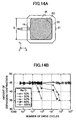
- a fifth modification differs from the first embodiment only in the point that the fifth modification includes the piezoelectric body 21 and the internal electrode layers 22 in place of the piezoelectric body 11 and the internal electrode layers 12 of the first embodiment (the piezoelectric/electrostrictive actuator 10), as shown in FIG. 14A, which is a cross sectional view of the piezoelectric/electrostrictive actuator of the fifth modification, taken along a plane extending along an internal electrode layer.
- the piezoelectric body 21 and the internal electrode layers 22 assume the respective shapes as described above.
- FIG. 14B is a graph showing changes in expansion/contraction amount of the piezoelectric body 21 with the number of drive cycles for the piezoelectric/electrostrictive actuator of the fifth modification.
- the marks in FIG. 14B are the same as those shown in FIG. 12B.
- a sixth modification differs from the first embodiment only in the point that the sixth modification includes a piezoelectric body 31, the internal electrode layers 32, and the electrode lead portions 24 in place of the piezoelectric body 11, the internal electrode layers 12, and the electrode lead portions 14 of the first embodiment (the piezoelectric/electrostrictive actuator 10), as shown in FIG. 15A, which is a cross sectional view of the piezoelectric/electrostrictive actuator of the sixth modification, taken along a plane extending along an internal electrode layer.
- the piezoelectric body 31 assumes a generally circular outer shape, and has a pair of flat side surfaces on which side-surface electrodes are formed.
- the internal electrode layers 32 and the electrode lead portions 24 assume the respective shapes as described above.
- FIG. 15B is a graph showing changes in expansion/contraction amount of the piezoelectric body 31 with the number of drive cycles for the piezoelectric/electrostrictive actuator of the sixth modification.
- the marks in FIG. 15B are the same as those shown in FIG. 12B.
- a seventh modification differs from the first embodiment only in the point that the seventh modification includes a piezoelectric body 41, the internal electrode layers 32, and the electrode lead portions 24 in place of the piezoelectric body 11, the internal electrode layers 12, and the electrode lead portions 14 of the first embodiment (the piezoelectric/electrostrictive actuator 10), as shown in FIG. 16A, which is a cross sectional view of the piezoelectric/electrostrictive actuator of the seventh modification, taken along a plane extending along an internal electrode layer.
- the piezoelectric body 41 assumes a circular outer shape.
- the internal electrode layers 32 and the electrode lead portions 24 assume the respective shapes as described above.
- FIG. 16B is a graph showing changes in expansion/contraction amount of the piezoelectric body 41 with the number of drive cycles for the piezoelectric/electrostrictive actuator of the seventh modification.
- the marks in FIG. 16B are the same as those shown in FIG. 12B.
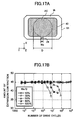
- An eighth modification differs from the first embodiment only in the point that the eighth modification includes a piezoelectric body 51, internal electrode layers 42, and the electrode lead portions 24 in place of the piezoelectric body 11, the internal electrode layers 12, and the electrode lead portions 14 of the first embodiment (the piezoelectric/electrostrictive actuator 10), as shown in FIG. 17A, which is a cross sectional view of the piezoelectric/electrostrictive actuator of the eighth modification, taken along a plane extending along an internal electrode layer.
- the piezoelectric body 51 assumes an octagonal outer shape obtained by chamfering corner portions of a rectangle.
- Each internal electrode layer 42 has a rectangular shape slightly smaller than the outer shape of the piezoelectric body 51 and its corners are rounded.
- each internal electrode layer 42 is parallel to the corresponding sides of the piezoelectric body 51, and the centroid of the internal electrode layer 42 coincides with the centroid of the piezoelectric body 51.
- Each electrode lead portion 24 has the shape as described above.
- FIG. 17B is a graph showing changes in expansion/contraction amount of the piezoelectric body 51 with the number of drive cycles for the piezoelectric/electrostrictive actuator of the eighth modification. The marks in FIG. 17B are the same as those shown in FIG. 12B.
- a ninth modification differs from the first embodiment only in the point that the ninth modification includes a piezoelectric body 61, internal electrode layers 52, and the electrode lead portions 24 in place of the piezoelectric body 11, the internal electrode layers 12, and the electrode lead portions 14 of the first embodiment (the piezoelectric/electrostrictive actuator 10), as shown in FIG. 18A, which is a cross sectional view of the piezoelectric/electrostrictive actuator of the ninth modification, taken along a plane extending along an internal electrode layer.
- the piezoelectric body 61 assumes an elliptical outer shape.
- Each internal electrode layer 52 has an elliptical outer shape slightly smaller than the outer shape of the piezoelectric body 61, and the major and minor axes of the internal electrode layer 52 coincide (overlap) with the major and minor axes of the piezoelectric body 61.
- Each electrode lead portion 24 has the shape as described above.
- FIG. 18B is a graph showing changes in expansion/contraction amount of the piezoelectric body 61 with the number of drive cycles for the piezoelectric/electrostrictive actuator of the ninth modification. The marks in FIG. 18B are the same as those shown in FIG. 12B.
- the piezoelectric body and the internal electrode layers of the present embodiment may be formed to assume various shapes as shown in FIGS. 19 to 21 in addition to those of the above-described modifications. Note that, in any of the embodiment and the modifications, the internal electrode layers have a higher degree of symmetry than does the piezoelectric body.
- the features of the shapes (shapes as shown from above) of the piezoelectric bodies and the internal electrode layers shown in these drawings will be described.
- the piezoelectric body, the internal electrode layers, the electrode lead portions, and the side-surface electrodes are denoted by reference numerals 81, 82, 83, and 84, respectively.
- FIG. 19A The piezoelectric body 81 is in the form of a square; and each internal electrode layer 82 is in the form of a regular octagon (shape of 8-fold symmetry).
- FIG. 19B The piezoelectric body 81 is in the form of a square; and each internal electrode layer 82 is in the form of a square having rounded corners.
- FIG. 19C The piezoelectric body 81 is in the form of an octagon obtained by chamfering the corners of a square; and each internal electrode layer 82 is in the form of a square.
- FIG. 20A The piezoelectric body 81 is in the form of a regular hexagon; and each internal electrode layer 82 is in the form of a regular hexagon slightly smaller than the outer shape of the piezoelectric body 81.
- FIG. 20B The piezoelectric body 81 is in the form of a regular hexagon; and each internal electrode layer 82 is in the form of a circle.
- FIG. 20C The piezoelectric body 81 is in the form of a regular octagon; and each internal electrode layer 82 is in the form of a regular octagon slightly smaller than the outer shape of the piezoelectric body 81.
- FIG. 20D The piezoelectric body 81 is in the form of a regular octagon; and each internal electrode layer 82 is in the form of a circle.
- a pair of internal electrode layers 82 shown in FIG. 21A are those facing each other.
- the piezoelectric body 81 is a rectangular shape as viewed from above.
- Each internal electrode layer 82 has a rectangular planar shape; and is connected to a pair of electrode lead portions 83, which extend along a straight line passing through the centroid of the internal electrode layer 82 as viewed from above.
- the extending direction of the electrode lead portions 83 connected to one internal electrode layer 82 perpendicularly intersects with the extending direction of the electrode lead portions 83 connected to the other internal electrode layer 82.
- a pair of internal electrode layers 82 shown in FIG. 21B are those facing each other.
- the piezoelectric body 81 is a regular hexagonal shape as viewed from above.
- Each internal electrode layer 82 has a circular planar shape; and is connected to a pair of electrode lead portions 83, which extend along a straight line passing through the centroid of the internal electrode layer 82 as viewed from above.
- the extending direction of the electrode lead portions 83 connected to one internal electrode layer 82 intersects by 60 degrees with respect to the extending direction of the electrode lead portions 83 connected to the other internal electrode layer 82.
- a pair of internal electrode layers 82 shown in FIG. 21C are those facing each other.
- the piezoelectric body 81 is a regular octagonal shape as viewed from above.
- Each internal electrode layer 82 has a regular octagonal planar shape; and is connected to four electrode lead portions 83, which extend along two straight lines perpendicularly intersecting each other and passing through the centroid of the internal electrode layer 82 as viewed from above.
- the extending directions of the electrode lead portions 83 connected to one internal electrode layer 82 are intersects by 45 degrees with respect to the extending directions of the electrode lead portions 83 connected to the other internal electrode layer 82.
- the shape (shape as viewed from above, or shape in a plane perpendicularly intersecting the thickness direction) of each internal electrode layer may be a shape having n-fold symmetry, where n is an integer not less than 2, a rectangular shape, an oval shape or an elliptical shape.
- n is an integer not less than 2
- n is an integer not less than 2
- n-fold symmetry means that, if an original shape is rotated by 360/n degrees (360° divided by an integer n), the rotated shape is identical to the original shape.
- a shape has "n-fold symmetry", if the shape rotated by 360/n degrees from an original position can be identical to the shape which stays at the original position.
- the shape of the internal electrodes has a high degree of symmetry, there can be provided a piezoelectric/electrostrictive actuator in which distortion generated in the active portion is efficiently used in expansion and contraction in a desired expansion/contraction direction (in this case, Z-axis direction), and excessive stress is not generated.
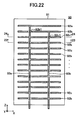
- the piezoelectric/electrostrictive actuator 90 includes a piezoelectric body 91 generally identical to the piezoelectric body 11; internal electrode layers 92a, 92b, and 92c; and electrode lead portions 93a and 93b.
- each of the internal electrode layers 92a, 92b, and 92c is substantially the same as the internal electrode layers 12. However, as shown in FIG. 23, each internal electrode layer 92b has a through hole 92b1 through which the electrode lead portion 93a passes in the Z-axis direction. As shown in FIG. 24, each internal electrode layer 92c has a through hole 92c1 through which the electrode lead portion 93b passes in the Z-axis direction.
- the internal electrode layer 92a is disposed at the top portion of the piezoelectric body 91, and the internal electrode layers 92b and 92c are alternately disposed toward the lower end of the piezoelectric body 91.
- the electrode lead portion 93a extends from the lower end of the piezoelectric body 91 into the interior of the piezoelectric body 91 in the Z-axis positive direction, is connected to the internal electrode layers 92c, while passing through the through holes 92b1 formed in the internal electrode layers 92b, and is finally connected to the internal electrode layer 92a.
- the spaces between the electrode lead portion 93a and the wall surfaces of the through holes 92b1 are filled with an insulating material (in the present example, the piezoelectric body 91).
- the electrode lead portion 93b extends from the lower end of the piezoelectric body 91 into the interior of the piezoelectric body 91 in the Z-axis positive direction, is connected to the internal electrode layer 92b in the lower end portion, is further connected to a plurality of the internal electrode layers 92b, while passing through the through holes 92c1 formed in the internal electrode layers 92c, and is finally connected to the uppermost internal electrode layer 92b.
- the spaces between the electrode lead portion 93b and the wall surfaces of the through holes 92c1 are filled with an insulating material (in the present example, the piezoelectric body 91).
- the electrode lead portions do not extend on the same planes as the internal electrode layers as in the case of the first embodiment. Therefore, an inactive portion can be formed to surround an active portion (central portion) without fail.
- the crack when a crack arises in the piezoelectric body of the piezoelectric/electrostrictive actuator, in which the internal electrode layers 12 are connected to the side-surface electrodes 13, as the first embodiment, the crack may progresses and causes the side-surface electrodes 13 to crack. If the side-surface electrodes 13 cracks, there may be one or more internal electrode layers 12 to which the predetermined voltages can not be applied.
- first supplemental electrodes 202 are fixed to the side-surface electrodes 13 (13a, 13b) through a solder layers 201.
- Each of the solder layers 201 is formed on each of the substantially entire surfaces of the side-surface electrodes 13.
- the first supplemental electrode 202 is a thin film electrode having a small thickness in the X-axis direction.
- the length of the first supplemental electrode 202 along the Y-axis direction is about the same as that of the side-surface electrodes 13 along the Y-axis direction.
- Second supplemental electrodes 203 are fixed to and contacted with the first supplemental electrodes 202.
- Each of the second supplemental electrodes 203 is a mesh-like electrode having elasticity. Therefore, a plurality of the internal electrode layers 12a (or a plurality of the internal electrode layers 12b) is electrically connected to one another through not only one of the side-surface electrodes 13 but also one supplemental electrode which includes one of the solder layers 201, one of the first supplemental electrodes 202, and one of the second supplemental electrodes 203.
- the predetermined voltage is applied to all of internal electrode layers 12a through the supplemental electrode.
- a piezoelectric/electrostrictive actuator which has higher reliability and can be more easily implemented is provided by manufacturing through "a simultaneous punching-laminating method" the piezoelectric/electrostrictive actuator in which a plurality of the internal electrode layers 92c are connected by the electrode lead portion 93a passing through the interior of the piezoelectric body 91 and a plurality of the internal electrode layers 92b are connected by the electrode lead portion 93b passing through the interior of the piezoelectric body 91, as the piezoelectric/electrostrictive actuator 90 shown in FIG. 22.
- the piezoelectric/electrostrictive actuator manufactured by "the simultaneous punching-laminating method” will be described.
- FIG. 26A is a cross sectional view of the piezoelectric/electrostrictive actuator 300 manufactured by "the simultaneous punching-laminating method", taken along a plane extending along an internal electrode layer.
- FIG. 26B is a vertical cross-sectional view of the actuator 300.
- the piezoelectric/electrostrictive actuator 300 includes a piezoelectric body 301, a plurality of internal electrode layers 302a, a plurality of internal electrode layers 302b, an electrode lead portion 303a, and an electrode lead portion 303b.
- the piezoelectric body 301 is a piezoelectric body similar to the piezoelectric body 41 whose outer shape is a circular column.
- Each of the internal electrode layers 302a is an internal electrode layer similar to the internal electrode layer 92b and formed on a plane along the X-Y plane.
- the diameter of the each of the internal electrode layers 302a is equal to the diameter of the piezoelectric body 301. That is, an outer circumference of each of the internal electrode layers 302a is exposed to the side surface of the piezoelectric/electrostrictive actuator 300.
- Each of the internal electrode layers 302a has a cylindrical through hole 302a1 and a cylindrical through hole 302a2.
- the radius of the through hole 302a1 is slightly larger than the radius of the through hole 302a2.
- Each of the internal electrode layers 302b is an internal electrode layer similar to the internal electrode layer 92c and formed on a plane along the X-Y plane.
- the diameter of the each of the internal electrode layers 302b is equal to the diameter of the piezoelectric body 301. That is, an outer circumference of each of the internal electrode layers 302b is exposed to the side surface of the piezoelectric/electrostrictive actuator 300.
- Each of the internal electrode layers 302b has a cylindrical through hole 302b1 and a cylindrical through hole 302b2.
- the radius of through hole 302b1 is slightly larger than the radius of the through hole 302b2.
- the internal electrode layers 302a and the internal electrode layers 302b are alternately disposed along the Z-axis direction such that one of the internal electrode layers 302a and one of the internal electrode layers 302b face each other.
- the distance between one of the internal electrode layer 302a and one of the internal electrode layer 302b adjacent to that one of the internal electrode layer 302a i.e., the thickness t of a single layer of the piezoelectric body is constant.
- the electrode lead portion 303a includes a hollow cylindrical section 303a1, a layer electrode section 303a2, conductive elastic members 303a3, and a mesh-like electrode 303a4.
- the hollow cylindrical section 303a1 is a space that is formed inside of the piezoelectric body 301 and has a hollow cylindrical shape.
- the hollow cylindrical section 303a1 has a center axis extending along the Z-axis.
- the hollow cylindrical section 303a1 is in communication with the bottom surface of the piezoelectric body 301 to form an opening on the bottom surface.
- the center axis of the hollow cylindrical section 303a1, and a center axis of each of the larger through holes 302a1 of the internal electrode layers 302a, and a center axis of each of the smaller through holes 302b2 of the internal electrode layers 302b are on a single straight line.
- the radius of the hollow cylindrical section 303a1 is smaller than the radius of the larger through hole 302a1 of the internal electrode layers 302a, and is equal to the radius of the smaller through hole 302b2 of the internal electrode layers 302b.
- the spaces between the hollow cylindrical section 303a1 and the larger through holes 302a1 of the internal electrode layers 302a are filled with an insulating material (which is, in the present example, the piezoelectric body 301).
- the layer electrode section 303a2 is a conductive thin film formed on an inside wall surface that defines the hollow cylindrical section 303a1.
- the layer electrode section 303a2 is connected with the internal electrode layers 302b physically and electrically.
- the conductive elastic members 303a3 and the mesh-like electrode 303a4 are inserted into the hollow cylindrical section 303a1.
- the conductive elastic members 303a3 and the mesh-like electrode 303a4 form a cylindrical member which tends to expand its diameter when it is inserted into the hollow cylindrical section 303a1. That is, the conductive elastic members 303a3 act to expand the mesh-like electrode 303a4.
- the mesh-like electrode 303a4 and the layer electrode section 303a2 are fixed each other through solder layers not shown. As a result, the mesh-like electrode 303a4 is electrically connected with the layer electrode section 303a2 steadily.
- the electrode lead portion 303b includes a hollow cylindrical section 303b1, a layer electrode section 303b2, conductive elastic members 303b3, and a mesh-like electrode 303b4.
- the hollow cylindrical section 303b1 is a space that is formed inside of the piezoelectric body 301 and has a hollow cylindrical shape.
- the hollow cylindrical section 303b1 has a center axis extending along the Z-axis.
- the center axis of the hollow cylindrical section 303b1 keeps away from the center axis of the hollow cylindrical section 303a1 by a predetermined distance.
- the radius of the hollow cylindrical section 303b1 is equal to the radius of the hollow cylindrical section 303a1.
- the hollow cylindrical section 303b1 is in communication with the bottom surface of the piezoelectric body 301 to form an opening on the bottom surface.
- the center axis of the hollow cylindrical section 303b1, and a center axis of each of the larger through holes 302b1 of the internal electrode layers 302b, and a center axis of each of the smaller through holes 302a2 of the internal electrode layers 302a are on a single straight line.
- the radius of the hollow cylindrical section 303b1 is smaller than the radius of the larger through hole 302b1 of the internal electrode layers 302b, and is equal to the radius of the smaller through hole 302a2 of the internal electrode layers 302a.
- the spaces between the hollow cylindrical section 303b1 and the larger through hole 302b1 of the internal electrode layers 302b are filled with an insulating material (which is, in the present example, the piezoelectric body 301).
- the layer electrode section 303b2 is a conductive thin film formed on the inside wall surface that defines the hollow cylindrical section 303b1.
- the layer electrode section 303b2 is connected with the internal electrode layers 302a physically and electrically.
- the conductive elastic members 303b3 and the mesh-like electrode 303b4 are inserted into the hollow cylindrical section 303b1.
- the conductive elastic members 303b3 and the mesh-like electrode 303b4 form a cylindrical member which tends to expand its diameter when it is inserted into the hollow cylindrical section 303b1. That is, the conductive elastic members 303b3 act to expand the mesh-like electrode 303b4.
- the mesh-like electrode 303b4 and the layer electrode section 303b2 are fixed each other through solder layers now shown. As a result, the mesh-like electrode 303b4 is electrically connected with the layer electrode section 303b2 steadily.
- the piezoelectric/electrostrictive actuator 300 having a construction described above expands and contracts along the Z-axis by applying the predetermined voltage to the internal electrode layers 302b and the internal electrode layers 302a through the layer electrode section 303a2 and the layer electrode section 303b2, respectively.
- the layer electrode section 303a2 has a crack and becomes broken, a plurality of the internal electrode layers 302b are kept in the conduction state one another through the mesh-like electrode 303a4.
- a plurality of the internal electrode layers 302a are kept in the conduction state one another through the mesh-like electrode 303b4.
- the predetermined voltage is applied to the internal electrode layers 302a and the internal electrode layers 302b, even when the layer electrode section 303a2 and/or the layer electrode section 303b2 have a crack.
- the simultaneous punching-laminating method for manufacturing the piezoelectric/electrostrictive actuator 300 is described by comparing with a conventional individual-punching and laminating method.
- the piezoelectric/electrostrictive actuator 300 can be manufactured by the conventional individual-punching and laminating method as well.
- manufacturing the piezoelectric/electrostrictive actuator 300 by the simultaneous punching-laminating method can yield a lot of advantages described later in detail.
- a cylindrical punch 401 and a die 402 are prepared as shown in FIG. 27. These are used to make circular (cylindrical) through holes that will become the hollow cylindrical sections 303a1 and 303b1.
- the die 402 has a through hole 402a through which the punch 401 passes.
- the radius of the through hole 402a is larger than the radius of the punch 401 by a distance L. That is, a clearance L is provided between the punch 401 and the die 402.
- a layer which will be the internal electrode layers 302a (or the internal electrode layers 302b) is formed on a piezoelectric ceramics green sheet by printing and the like.
- the through holes 302a1 and 302a2 (or the through holes 302b1 and 302b2) are formed.
- the piezoelectric ceramics green sheet SG is disposed on the die 402, and is punched out using the cylindrical punch 401.
- punching as shown by the dotted line in FIG. 27, a crack occurs from each of the edges of the punch 401 and the die 402.
- cross-sectional shape of the thus-formed through hole has a tapered shape whose diameter increases with respect to the punching out direction.
- the layer electrode sections 303a2 and 303b2 are formed by plating or dipping in the hollow cylindrical sections 303a1 and 303b1.
- the conductive elastic members 303a3 and the mesh-like electrode 303a4 are inserted into the hollow cylindrical section 303a1 and are fixed to the layer electrode sections 303a2 by soldering.
- the conductive elastic members 303b3 and the mesh-like electrode 303b4 are inserted into the hollow cylindrical section 303b1 and are fixed to the layer electrode sections 303b2 by soldering.
- FIG. 29 is an enlarged sectional view of the hollow cylindrical section 303a1 of the piezoelectric/electrostrictive actuator 300 manufactured by the method described above.
- the through hole of each of the ceramics green sheets SG has tapered shape. Therefore, the inside wall surface of the thus-manufactured hollow cylindrical section 303a1 is not flat due to the tapered shape. This may cause a sharp corner to exist at a boundary portion between one layer of the piezoelectric body and another layer adjacent to that one layer of the piezoelectric body (these layers are integrated by the firing). As a result, a crack may be initiated from the sharp corner in the layer of the piezoelectric body.
- a punch 411, a die 412, and a stripper 413 shown in FIG. 30 are used to form circular (cylindrical) through holes that will become the hollow cylindrical sections 303a1 and 303b1.
- the first piezoelectric ceramics green sheet SG1 is disposed on the die 412. Note that a layer which will be the internal electrode layer 302a (or the internal electrode layer 302b) has been formed on the sheet SG1 by printing and the like.
- the through holes 302a1 and 302a2 (or the through holes 302b1 and 302b2) have also been formed.
- the ceramics green sheet SG1 is punched out by using punch 411 having a pair of cylindrical portions. Thereafter, as shown in FIG. 32, the ceramics green sheet SG1 is moved upward together with punch 411 while the ceramics green sheet SG1 is appressed to the stripper 413 without pulling out the punch 411 from the ceramics green sheet SG1. For example, the ceramics green sheet SG1 is appressed to the stripper 413 by suction using through holes 413a formed in the stripper 413.
- a head of the punch 411 (ends of the cylindrical portions) is disposed at a position lower than a center of each of the through holes formed in the ceramics green sheet SG1 along the axis of each of the through holes. That is, the punch 411 is kept inserted in the ceramics green sheet SG1 at a position where the punch 411 is pulled slightly upward (i.e., pulling out direction) from the bottom surface of the ceramics green sheet SG1.
- the second piezoelectric ceramics green sheet SG2 is disposed on the die 412.
- the first sheet SG1 a layer which will be the internal electrode layer has been formed on the sheet SG2 by printing and the like.
- the through holes 302a1 and 302a2 (or the through holes 302b1 and 302b2) have also been formed.
- the punch 411, the stripper 413, and the first piezoelectric ceramics green sheet SG1 are moved downward to punch out the second piezoelectric ceramics green sheet SG2 by the punch 411.
- the ceramics green sheets SG1 and SG2 are moved upward together with the punch 411 and the stripper 413 without pulling out the punch 411 from the ceramics green sheets SG1 and SG2.
- a required number of the ceramics green sheets are laminated while forming through holes by punching in the ceramics green sheets simultaneously.
- the punch 411 is pulled out from the laminated ceramics green sheets.
- the laminated ceramics green sheets are moved to a different place to be fired. Thereafter, with a method similar to the method described above, the layer electrode sections 303a2 and 303b2 are formed.
- the conductive elastic members 303a3 and the mesh-like electrode 303a4 are fixed to the layer electrode sections 303a2 by soldering, the conductive elastic members 303b3 and the mesh-like electrode 303b4 are fixed to the layer electrode sections 303b2 by soldering.
- the piezoelectric/electrostrictive actuator 300 is manufactured
- the piezoelectric/electrostrictive actuator 300 manufactured by the simultaneous punching-laminating method provides advantages described below. Note that, hereinafter, the description is made with respect to the hollow cylindrical section 303a1, however, the same is true for the hollow cylindrical section 303b1.
- the piezoelectric/electrostrictive actuators according to the embodiments of the present invention have enhanced durability and increased expansion and contraction amounts.
- the present invention is not limited to the above-described embodiments, and various modifications may be employed without departing from the scope of the invention.
- the planar shape of the internal electrode layers are not limited to regular polygons, and may be an irregular polygon, a regular polygon having rounded corners, or an irregular polygon having rounded corners.
- the piezoelectric body in the above-described embodiments may be an electrostrictive body which expands along the direction of an applied electric field.
Landscapes
- General Electrical Machinery Utilizing Piezoelectricity, Electrostriction Or Magnetostriction (AREA)
- Fuel-Injection Apparatus (AREA)
Applications Claiming Priority (2)
| Application Number | Priority Date | Filing Date | Title |
|---|---|---|---|
| JP2006018865 | 2006-01-27 | ||
| JP2006258089A JP2007227872A (ja) | 2006-01-27 | 2006-09-22 | 圧電/電歪アクチュエータ |
Publications (2)
| Publication Number | Publication Date |
|---|---|
| EP1814170A2 true EP1814170A2 (fr) | 2007-08-01 |
| EP1814170A3 EP1814170A3 (fr) | 2008-07-09 |
Family
ID=37451188
Family Applications (1)
| Application Number | Title | Priority Date | Filing Date |
|---|---|---|---|
| EP20060255108 Withdrawn EP1814170A3 (fr) | 2006-01-27 | 2006-10-03 | Actionneur piézo-electrique/électrostrictif |
Country Status (3)
| Country | Link |
|---|---|
| US (1) | US20070176520A1 (fr) |
| EP (1) | EP1814170A3 (fr) |
| JP (1) | JP2007227872A (fr) |
Cited By (9)
| Publication number | Priority date | Publication date | Assignee | Title |
|---|---|---|---|---|
| WO2007141137A3 (fr) * | 2006-06-08 | 2008-03-20 | Bosch Gmbh Robert | Actionneur piézoélectrique |
| US8544316B2 (en) | 2011-07-18 | 2013-10-01 | Korea Institute Of Industrial Technology | Micro viscometer |
| WO2013172513A1 (fr) * | 2012-05-18 | 2013-11-21 | 한국생산기술연구원 | Micro-viscosimètre et son procédé de fabrication |
| US8667831B2 (en) | 2011-07-18 | 2014-03-11 | Korea Institute Of Industrial Technology | Micro viscometer |
| US8677807B2 (en) | 2011-07-18 | 2014-03-25 | Korea Institute Of Industrial Technology | Micro viscometer |
| US9128022B2 (en) | 2012-05-18 | 2015-09-08 | Korea Institute Of Industrial Technology | Micro viscometers and methods of manufacturing the same |
| US9554259B2 (en) | 2013-11-15 | 2017-01-24 | Htc Corporation | Methods for handling a service request procedures, and apparatuses using the same |
| EP3188506A4 (fr) * | 2014-08-28 | 2018-06-06 | Kyocera Corporation | Élément piézoélectrique et générateur acoustique, dispositif de génération de son et appareil électronique équipé de celui-ci |
| EP4535975A3 (fr) * | 2023-10-06 | 2025-07-09 | LG Display Co., Ltd. | Dispositif de vibration piézoélectrique multicouche et appareil électronique le comprenant |
Families Citing this family (6)
| Publication number | Priority date | Publication date | Assignee | Title |
|---|---|---|---|---|
| DE102006062076A1 (de) * | 2006-12-29 | 2008-07-10 | Siemens Ag | Piezokeramischer Vielschichtaktor und Verfahren zu seiner Herstellung |
| JP5138407B2 (ja) * | 2008-02-14 | 2013-02-06 | セイコーインスツル株式会社 | ウエハ及びウエハ研磨方法 |
| DE102008062021A1 (de) * | 2008-08-18 | 2010-03-04 | Epcos Ag | Piezoaktor in Vielschichtbauweise |
| JP6047317B2 (ja) * | 2012-06-29 | 2016-12-21 | 日本特殊陶業株式会社 | 圧電素子 |
| JP6133655B2 (ja) * | 2013-03-29 | 2017-05-24 | 日本碍子株式会社 | 圧電/電歪素子とその製造方法 |
| JP6683476B2 (ja) * | 2015-12-25 | 2020-04-22 | 日本特殊陶業株式会社 | 圧電素子およびその製造方法、異物除去ユニットならびに超音波センサ |
Family Cites Families (4)
| Publication number | Priority date | Publication date | Assignee | Title |
|---|---|---|---|---|
| EP0094078B1 (fr) * | 1982-05-11 | 1988-11-02 | Nec Corporation | Elément électrostrictif multicouche résistant à l'application répétée d'impulsions |
| US4471256A (en) * | 1982-06-14 | 1984-09-11 | Nippon Soken, Inc. | Piezoelectric actuator, and valve apparatus having actuator |
| US5089739A (en) * | 1990-03-19 | 1992-02-18 | Brother Kogyo Kabushiki Kaisha | Laminate type piezoelectric actuator element |
| JP2986706B2 (ja) * | 1995-03-03 | 1999-12-06 | 日立金属株式会社 | 圧電素子及びそれを用いた圧電アクチュエータ |
-
2006
- 2006-09-22 JP JP2006258089A patent/JP2007227872A/ja active Pending
- 2006-09-29 US US11/536,810 patent/US20070176520A1/en not_active Abandoned
- 2006-10-03 EP EP20060255108 patent/EP1814170A3/fr not_active Withdrawn
Cited By (10)
| Publication number | Priority date | Publication date | Assignee | Title |
|---|---|---|---|---|
| WO2007141137A3 (fr) * | 2006-06-08 | 2008-03-20 | Bosch Gmbh Robert | Actionneur piézoélectrique |
| US8544316B2 (en) | 2011-07-18 | 2013-10-01 | Korea Institute Of Industrial Technology | Micro viscometer |
| US8667831B2 (en) | 2011-07-18 | 2014-03-11 | Korea Institute Of Industrial Technology | Micro viscometer |
| US8677807B2 (en) | 2011-07-18 | 2014-03-25 | Korea Institute Of Industrial Technology | Micro viscometer |
| WO2013172513A1 (fr) * | 2012-05-18 | 2013-11-21 | 한국생산기술연구원 | Micro-viscosimètre et son procédé de fabrication |
| US9128022B2 (en) | 2012-05-18 | 2015-09-08 | Korea Institute Of Industrial Technology | Micro viscometers and methods of manufacturing the same |
| US9554259B2 (en) | 2013-11-15 | 2017-01-24 | Htc Corporation | Methods for handling a service request procedures, and apparatuses using the same |
| EP3188506A4 (fr) * | 2014-08-28 | 2018-06-06 | Kyocera Corporation | Élément piézoélectrique et générateur acoustique, dispositif de génération de son et appareil électronique équipé de celui-ci |
| US10333051B2 (en) | 2014-08-28 | 2019-06-25 | Kyocera Corporation | Piezoelectric element, and acoustic generator, acoustic generation device, and electronic apparatus employing same |
| EP4535975A3 (fr) * | 2023-10-06 | 2025-07-09 | LG Display Co., Ltd. | Dispositif de vibration piézoélectrique multicouche et appareil électronique le comprenant |
Also Published As
| Publication number | Publication date |
|---|---|
| JP2007227872A (ja) | 2007-09-06 |
| US20070176520A1 (en) | 2007-08-02 |
| EP1814170A3 (fr) | 2008-07-09 |
Similar Documents
| Publication | Publication Date | Title |
|---|---|---|
| EP1814170A2 (fr) | Actionneur piézo-electrique/électrostrictif | |
| JP4525753B2 (ja) | 積層セラミックコンデンサ | |
| JP3901697B2 (ja) | 積層コンデンサ | |
| KR20180119935A (ko) | 커패시터 및 이를 포함하는 실장기판 | |
| JP2019175902A (ja) | チップ部品の整列方法及び磁石 | |
| US9934908B2 (en) | Aligning device and method for producing electronic component using the aligning device | |
| JP2010507222A (ja) | 圧電アクチュエータユニット及びその製造方法 | |
| EP4177976B1 (fr) | Élément piézoélectrique | |
| CN116210370B (zh) | 压电致动器 | |
| JP6144577B2 (ja) | 圧電アクチュエータ | |
| JPH0353572A (ja) | 電歪効果素子 | |
| CN111865138A (zh) | 长行程压电陶瓷致动器及其加工方法 | |
| JP7804513B2 (ja) | 圧電素子 | |
| JP7762107B2 (ja) | 圧電素子 | |
| JP2005045086A (ja) | インジェクタ装置用積層型圧電素子 | |
| JP6159985B2 (ja) | 圧電素子、圧電アクチュエータおよびこれらの製造方法 | |
| JP5153095B2 (ja) | 積層型圧電素子およびこれを用いた噴射装置 | |
| EP4102582A1 (fr) | Élément piézoélectrique | |
| JP2006286774A (ja) | 積層型圧電アクチュエータおよび積層型圧電アクチュエータ接着体 | |
| JP7172401B2 (ja) | 圧電アクチュエータおよび圧電駆動装置 | |
| JPS6231182A (ja) | 積層型圧電体 | |
| JP2001077436A (ja) | 積層型圧電アクチュエータ | |
| JP2023151284A (ja) | 圧電素子 | |
| KR100612800B1 (ko) | 전계에 의한 응력발생을 감소시킬 수 있도록 구성된 압전적층 액추에이터 | |
| JPH0457374A (ja) | 電歪効果素子 |
Legal Events
| Date | Code | Title | Description |
|---|---|---|---|
| PUAI | Public reference made under article 153(3) epc to a published international application that has entered the european phase |
Free format text: ORIGINAL CODE: 0009012 |
|
| 17P | Request for examination filed |
Effective date: 20061023 |
|
| AK | Designated contracting states |
Kind code of ref document: A2 Designated state(s): AT BE BG CH CY CZ DE DK EE ES FI FR GB GR HU IE IS IT LI LT LU LV MC NL PL PT RO SE SI SK TR |
|
| AX | Request for extension of the european patent |
Extension state: AL BA HR MK YU |
|
| PUAL | Search report despatched |
Free format text: ORIGINAL CODE: 0009013 |
|
| AK | Designated contracting states |
Kind code of ref document: A3 Designated state(s): AT BE BG CH CY CZ DE DK EE ES FI FR GB GR HU IE IS IT LI LT LU LV MC NL PL PT RO SE SI SK TR |
|
| AX | Request for extension of the european patent |
Extension state: AL BA HR MK RS |
|
| STAA | Information on the status of an ep patent application or granted ep patent |
Free format text: STATUS: THE APPLICATION HAS BEEN WITHDRAWN |
|
| 18W | Application withdrawn |
Effective date: 20081031 |