EP1814211A2 - Rauschunterdrückungsstruktur eines Gebläsemotors - Google Patents
Rauschunterdrückungsstruktur eines Gebläsemotors Download PDFInfo
- Publication number
- EP1814211A2 EP1814211A2 EP07001630A EP07001630A EP1814211A2 EP 1814211 A2 EP1814211 A2 EP 1814211A2 EP 07001630 A EP07001630 A EP 07001630A EP 07001630 A EP07001630 A EP 07001630A EP 1814211 A2 EP1814211 A2 EP 1814211A2
- Authority
- EP
- European Patent Office
- Prior art keywords
- metal terminal
- blower motor
- noise suppression
- terminal member
- suppression structure
- Prior art date
- Legal status (The legal status is an assumption and is not a legal conclusion. Google has not performed a legal analysis and makes no representation as to the accuracy of the status listed.)
- Withdrawn
Links
Images


Classifications
-
- H—ELECTRICITY
- H02—GENERATION; CONVERSION OR DISTRIBUTION OF ELECTRIC POWER
- H02K—DYNAMO-ELECTRIC MACHINES
- H02K11/00—Structural association of dynamo-electric machines with electric components or with devices for shielding, monitoring or protection
- H02K11/02—Structural association of dynamo-electric machines with electric components or with devices for shielding, monitoring or protection for suppression of electromagnetic interference
- H02K11/026—Suppressors associated with brushes, brush holders or their supports
Definitions
- the present invention relates to a noise suppression structure of a blower motor provided with noise suppression parts therein. More particularly, the invention relates to a noise suppression structure of a blower motor used in an air conditioner mounted in a vehicle.
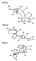
- Japanese utility model publication No. S62-124292 discloses the noise suppression structure of a fuel pump, in which a bracket member 2 made of a resin is provided on a front end opening 1a of a cylindrical motor housing 1, and an end bracket member 3 also made of a resin is provided on a rear end opening 1b of the motor housing 1. Both ends of a motor rotary shaft member 4 are supported rotatably thereby.
- the motor rotary shaft member 4 is provided with a commutator 5, and a pair of brush members 6 is disposed to oppose the commutator 5.
- Pigtails 7 including metal strands and derived from the brush members 6 are connected through choke coils 8 as noise reduction members with lead wires 9 derived from the front end opening 1a, respectively.
- the lead wires 9 derived from the front end opening 1a are connected with wires for externally supplying current and so on.
- the present invention has been made in view of the above-described problems, and therefore, at least one objective of the present invention is to provide a noise suppression structure of a blower motor capable of providing noise reduction members with fine space efficiency, and in which workability in assembling is good.
- the invention provides a noise suppression structure of a blower motor, which comprises: a bottomed, substantially cylindrical-shaped end bracket member including a peripheral wall part and a bottom surface part, the peripheral wall part being provided between the bottom surface part and a housing and an end edge of the peripheral wall part being configured to be mounted to an one end opening of the housing, and the bottom surface part being integrally formed with the peripheral wall part, rotatably supporting one end of a motor rotary shaft part and covering the one end opening of the housing; a connector part disposed in the end bracket member, provided in the peripheral wall part, and to which electric power is externally supplied; a metal terminal member provided in the end bracket member, coupled to the connector part, and including an extension part being extendedly provided along the bottom surface part in a circumferential direction of the bottom surface part and having a connection part; a brush member provided in the end bracket member and opposing a commutator mounted to the motor rotary shaft
- the noise reduction member includes a choke coil
- the noise suppression structure of the blower motor further comprises a guide member protruded from the bottom surface part toward an inside part of the blower motor, having a constant height, and configured to guide a conductor of the choke coil along the bottom surface part in the circumferential direction of the bottom surface part
- the guide member includes a metal terminal guide surface part on an upper surface thereof configured to slide and guide the metal terminal member when the metal terminal member is mounted to the connector part from the inside part of the blower motor.
- the guide member includes a stopper part on a side surface of the guide member facing the connector part, which contacts with a rear end part of the metal terminal member to prevent the metal terminal member from coming off the connector part.
- the connector part includes an insertion hole to which a part of the metal terminal member is inserted, and a size of the insertion hole is set in a size in which insertion of the metal terminal member in an oblique direction is tolerated.
- the bottom surface part includes a reinforcement rib part, and an upper surface of the reinforcement rib part is provided with a supporting surface part which contacts with the metal terminal member from below to support the metal terminal member.
- the guide member includes an inclined guide surface part between the metal terminal guide surface part and a side surface of the guide member facing the connector part, and the inclined guide surface part is slanted to have a constant dimension of drop.
- the extension part of the metal terminal member includes a caulking part adapted to be fixed to the bottom surface part of the end bracket member.
- the bottom surface part of the end bracket member includes a slide groove part which penetrates the bottom surface part and to which the caulking part is inserted to be caulked and fixed.
- the connector part includes a caulking hole to which a part of the metal terminal member is inserted and caulked.
- the bottom surface part includes a welding hole to which an electrode is inserted to connect the noise reduction member with the connection part of the extension part of the metal terminal member by resistance welding.
- the end bracket member includes a supporting pin member protruded from the bottom surface part toward an inside part of the blower motor for supporting a brush holder member, and the brush member is slidably held in the brush holder member.
- the conductor of the choke coil includes a bending point in which the conductor is bent to extend substantially linearly toward the connection part of the of the extension part of the metal terminal member.
- a rear end part of the metal terminal member is chamfered such that the metal terminal member smoothly slides and contacts with the metal terminal guide surface part of the guide member.
- the metal terminal member includes a pair of guide protrusions
- the bottom surface part includes guide protrusions protrudedly provided toward inside of the blower motor from the bottom surface part, and an end part of the conductor of the choke coil on a side of the connecter part extends to be located between the pair of guide protrusions of the metal terminal member 19 and protruded therefrom, and the protruded end part of the conductor is mounted between the guide protrusions.
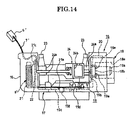
- FIGs. 1 to 18 illustrate a noise suppression structure of a blower motor according to an embodiment of the invention.
- a housing 11 structuring a main body of a motor and preferably made of a metal includes a cylindrical body part 13, and an end part 12 substantially conical in shape and formed integrally with the body part 13.
- One end of a motor rotary shaft member 4' is rotatably supported by the end part 12 through a bearing member 14.
- the housing 11 is provided with an end bracket member 15 preferably made of a resin on an one end opening 11 a located on a rear end side thereof
- the end bracket member 15 is mainly structured such that an end edge 16b of a peripheral wall part 16 substantially in a cylindrical shape is fitted to the one end opening 11a formed on a rear end of the body part 13 of the housing 11.
- the end bracket member 15 includes a bottom surface part 17 substantially in a circular shape as seen from a lower surface thereof and formed integrally with the peripheral wall part 16 in such a manner as to cover the one end opening 11 a.
- the end bracket member 15 is structured to have a bottomed, substantially cylindrical configuration.
- an one end 4a of the motor rotary shaft member 4' is rotatably supported by a central part of the bottom surface part 17 through the bearing member 14.
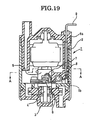
- inside of the end bracket member 15 is provided with a connector part 18 to which electric power is externally supplied.
- the connector part 18 includes a female connector concave part 18a to which a not-illustrated male connector member is fitted and formed in a concave shape.
- the female connector concave part 18a includes a partition wall surface part 18b.
- the partition wall surface part 18b is formed with a pair of insertion holes 18c to which contacts 19a of metal terminal members 19 are respectively inserted from inside to outside of the end bracket member 15.
- the insertion holes 18c are formed to have a two-straight-line shape.
- partition wall surface part 18b of the female connector concave part 18a is formed with pairs of upper and lower caulking holes 18d on left and right sides of the pair of insertion holes 18c, to which front surface caulking parts 19e of the metal terminal members 19 are respectively inserted and caulked.
- noise-killer capacitor member 20 illustrated in FIGs. 2 and 13 as one of noise reduction members is connected and caulked by rear side caulking parts 19b in such a manner that the noise-killer capacitor member 20 connects the metal terminal members 19.
- the metal terminal members 19 are respectively provided to be connected electrically with brush members 6' each opposing a commutator 5' mounted to the motor rotary shaft member 4'. Between the metal terminal members 19 and the brush members 6', there are interposed choke coil members 8' as one of the noise reduction members, conversion plates 22 and pigtails 7', respectively.
- the bottom surface part 17 of the end bracket member 15 is provided with supporting pin members 23 protruded upwardly from the bottom surface part 17.
- the bottom surface part 17 is integrally formed with a total of four supporting pin members 23.
- the supporting pin members 23 support a brush holder member 24 through rubber bushes 24a, respectively.
- the brush members 6' are held in a holder part 24b of the brush holder member 24 in such a manner that the brush members 6' are freely slideable by bias of not-illustrated biasing members such as spring members or the like toward inside substantially in a radial direction of the brush holder member 24.
- the peripheral wall part 16 provided between the bottom surface part 17 and the housing 11 in the end bracket member 15 is provided with the connector part 18.
- the choke coils 8' as one of the noise reduction members are provided inside of the peripheral wall part 16 of the end bracket member 15, and the choke coils 8' are located on a cooling air intake side which is an opposite side of the part to which the connector part 18 is provided in the peripheral wall part 16 of the end bracket member 15.
- Each of the metal terminal members 19 extendedly provided from the connector part 18 includes an extension part 19c.
- the extension part 19c of the metal terminal member 19 is flexed substantially in an S-like configuration as seen from above, and is extendedly provided along the bottom surface part 17 in a circumferential direction S.
- the extension part 19c of the metal terminal member 19 includes a connection part 19d to which a derivation coil winding 21 a as a conductor extendedly provided from a winding 21 of the choke coil 8' is connected by resistance welding for example.
- the derivation coil winding 21 a of the winding 21 or a coil body 21 is extendedly provided substantially linearly along the circumferential direction S directly, flexed once in a bending point 21 b, and then extendedly provided substantially linearly toward the connection part 19d.
- the derivation coil winding 21a is interposed and fixed between a metal sheet or a metal plate, preferably a copper sheet or a copper plate formed by cut and raise of the connection part 19d, and the connection part 19d.
- the derivation coil winding 21a interposed between the metal sheet or the metal plate and the connection part 19d is preferably welded by resistance welding in which electrodes are caused to contact therewith from upper and lower directions.
- An other end 21 c of the winding 21 of the choke coil 8' is connected with the conversion plate 22, and thus, the other end 21c of the winding 21 of the choke coil 8 is electrically connected with the brush member 6' through the pigtail 7' connected with the conversion plate 22.
- the derivation coil winding 21a of the choke coil 8' is guided along the circumferential direction S by guide members 25 protrudedly provided near the bending point 21b toward inside of the motor from the bottom surface part 17 of the end bracket member 15 and having a constant height.
- an end part of the derivation coil winding 21 a of the choke coil 8' on a side of the connecter part 18 is located between a pair of guide protrusions 19g of the metal terminal member 19 and protruded therefrom, and is mounted between guide protrusions 17e protrudedly provided toward inside of the motor from the bottom surface part 17 and which has a constant height.
- An interspace through which the derivation coil winding 21 a is inserted is provided between the guide members 25.
- each of the guide members 25 there is provided a metal terminal guide surface part 25a for slidingly guiding the metal terminal member 19 when the metal terminal member 19 is to be inserted into the insertion hole 18c formed on the connector part 18 from inside of the motor and mounted thereto.
- each of the guide members 25 on the side of the connecter part 18 there is formed a stopper part 25b for contacting a rear end part 19h of the metal terminal member 19.
- the stopper part 25b on the connector part side of the guide member 25 contacts with the rear end part 19h of the metal terminal member 19 in a state in which the contact 19a of the metal terminal member 19 is inserted into the insertion hole 18c formed on the connector part 18 from inside of the motor, such that the contact 19a is prevented from coming off the insertion hole 18c of the connector part 18.
- an inclined guide surface part 25c including a partially cut slanted surface and having a constant dimension h1 of drop or gap is provided between the metal terminal guide surface part 25a and the side surface on the connecter part side provided with the stopper part 25b of the guide member 25.
- a lower surface side of the rear end part 19h of the metal terminal member 19 is chamfered such that the metal terminal member 19 smoothly slides and contacts with the inclined guide surface part 25c.
- an upper surface side of the rear end part 19h may also be chamfered substantially symmetrically such that the end part of the derivation coil winding 21a is prevented from being damaged by contact.
- a size of the insertion hole 18c of the connector part 18 into which the contact 19a of the metal terminal member 19 is inserted is set to be in a size in which insertion of the contact 19a from an oblique direction is tolerated.
- a part of the extension part 19c of the metal terminal member 19 which is nearer to a side of the choke coil 8' than the connection part 19d includes lower surface caulking parts 19f as calking parts which are fixed to the bottom surface part 17 by being inserted into a pair of slide groove parts 17a penetratedly formed in the bottom surface part 17 of the end bracket member 15 and caulked thereto.
- parts of the pair of slide groove parts 17a to which the lower surface caulking parts 19f are caulked, respectively are set to be narrower in width than other parts.
- an upper surface of each of the reinforcement rib parts 17c provided on the bottom surface part 17 is formed with a supporting surface part 17d which extends substantially horizontally and contacts with the metal terminal member 19 from below to support the metal terminal member 19.
- the contacts 19a are obliquely inserted into the insertion holes 18c formed on the partition wall surface part 18b, respectively, when the pair of metal terminal members 19 is to be attached to the connector part 18 of the end bracket member 15.
- the caulking parts 19e are inserted into the pairs of upper and lower caulking holes 18d in such a manner that the caulking parts 19e are inserted substantially in parallel with the bottom surface part 17.
- the lower surface caulking parts 19f are caulked to a peripheral part, formed narrower in width, of the slide groove parts 17a.
- the front surface caulking parts 19e are also caulked to the partition wall surface part 18b, as illustrated in FIG. 13.
- a pair of leg-like terminals of the noise-killer capacitor member 20 is each caulked to the rear side caulking part 19b to connect both of the metal terminal members 19.
- the leg-like terminals of the noise-killer capacitor member 20 may be further connected with the rear side caulking parts 19b by solder.
- the derivation coil windings 21a of the choke coils 8' installed on the opposite side of the connector part 18 in the end bracket member 15 are interposed between the not-illustrated metal plates or sheets and the connection parts 19d, respectively, and the electrodes are inserted from the upper and lower directions through welding holes 17b to contact each of the interposed part so as to perform the resistance welding.
- the brush holder member 24 is mounted on the supporting pin members 23 through the rubber bushes 24a, and the brush members 6' are inserted in the holder part 24b of the brush holder member 24, as illustrated in FIG. 15.
- the brush members 6' are biased by the not-illustrated biasing members such as the spring members or the like toward inside substantially in the radial direction, such that the brush members 6' are each held slideably.
- the end bracket member 15 assembled as described above in accordance with the present preferred embodiment is mounted with the motor rotary shaft member 4' rotatably, and the end edge 16b of the end bracket member 15 is fitted to the one end opening 11a on the rear end side of the housing 11 to be mounted, in such a manner that the peripheral wall part 16 is located between the bottom surface part 17 and the housing 11.
- the extension part 19c of the metal terminal member 19, extendedly provided from the connector part 18, is provided with the connection part 19d for connecting the derivation coil winding 21a of the choke coil 8'.
- connection part 19d of the metal terminal member 19 in the outer circumferential direction S of the bottom surface part 17 and adjacent to the choke coil 8'.
- extension part 19c extendedly provided in the circumferential direction S along the bottom surface part 17 includes the connection part 19d, connection of the metal terminal member 19 and the derivation coil winding 21a through the welding hole 17b near the bottom surface part 17 is possible.
- the derivation coil winding 21 a of the choke coil 8' is structured by directly extending the winding from the coil body 21, it is possible to reduce influence on the connection in the connection part 19d even when the residual stress exists, since the distance from the choke coil 8' to the connection part 19d of the metal terminal member 19 is short and the derivation coil winding 21a of the choke coil 8' after the connection is guided by the guide members 25.
- the metal terminal member 19 When the metal terminal member 19 is attached to the connector part 18 from inside of the motor, the metal terminal member 19 smoothly slides and guided obliquely by the metal terminal guide surface part 25a provided on the upper surface of the guide member 25.
- the rear end part 19h of the metal terminal member 19 contacts with the stopper part 25b provided in the guide member 25, so as to prevent the contact 19a from coming off the connector part 18.
- the insertion hole 18c formed on the partition wall surface part 18b of the connector part 18 is set to be in the size in which the insertion of the contact 19a of the metal terminal member 19 in the oblique direction is tolerated. Therefore, workability in insertion of the metal terminal member 19 is good.
- the metal terminal member 19 is caulked and fixed to the bottom surface part 17 of the end bracket member 15 by the lower surface caulking parts 19f provided in the extension part 19c of the metal terminal member 19.
- the lower surface caulking parts 19f of the metal terminal member 19 are caulked to the peripheral part of the slide groove parts 17a formed narrow in width. Therefore, not only movement of the metal terminal member 19 in the upper and the lower directions but also the movement thereof in a direction of slide along the bottom surface part 17 is prevented.
- the upper surface of the reinforcement rib part 17c provided on the bottom surface part 17 is formed with the supporting surface part 17d which contacts with the metal terminal member 19 from the lower surface side of the metal terminal member 19 and support the metal terminal member 19.
- the mounting of the metal terminal member 19 in accordance with the slide movement thereof is carried out further smoothly by the inclined guide surface part 25c provided between the metal terminal guide surface part 25a and the side surface on the connector part side of the guide member 25.
- the metal terminal member 19 is formed substantially in the S-like configuration as seen from the top, and the part of the extension part 19c of the metal terminal member 19 nearer to the side of the choke coil 8' than the connection part 19d includes the lower surface caulking parts 19f as the calking parts fixed to the bottom surface part 17 by being inserted into the pair of slide groove parts 17a penetratedly formed in the bottom surface part 17 of the end bracket member 15 and caulked thereto, but it is not limited thereto.
- the lower surface caulking parts 19f are formed near the connection part 19d, or formed nearer to the side of the connector part 18 than the connection part 19d. Any shape such as a straight line shape, an arch-like shape or a combination of shapes can be employed for the shape of the metal terminal member 19 as long as the metal terminal member 19 extends in the circumferential direction along the bottom surface part.
- the number of the metal terminal member 19 and a material used therefor are not limited to the above-described embodiments.
Landscapes
- Physics & Mathematics (AREA)
- Electromagnetism (AREA)
- Engineering & Computer Science (AREA)
- Power Engineering (AREA)
- Motor Or Generator Frames (AREA)
Applications Claiming Priority (1)
| Application Number | Priority Date | Filing Date | Title |
|---|---|---|---|
| JP2006015787A JP4864469B2 (ja) | 2006-01-25 | 2006-01-25 | ブロワモータのラジオノイズ対策構造 |
Publications (2)
| Publication Number | Publication Date |
|---|---|
| EP1814211A2 true EP1814211A2 (de) | 2007-08-01 |
| EP1814211A3 EP1814211A3 (de) | 2009-12-30 |
Family
ID=38107099
Family Applications (1)
| Application Number | Title | Priority Date | Filing Date |
|---|---|---|---|
| EP07001630A Withdrawn EP1814211A3 (de) | 2006-01-25 | 2007-01-25 | Rauschunterdrückungsstruktur eines Gebläsemotors |
Country Status (3)
| Country | Link |
|---|---|
| US (1) | US7855479B2 (de) |
| EP (1) | EP1814211A3 (de) |
| JP (1) | JP4864469B2 (de) |
Cited By (1)
| Publication number | Priority date | Publication date | Assignee | Title |
|---|---|---|---|---|
| DE102012106224B4 (de) | 2011-07-12 | 2021-09-02 | Johnson Electric International AG | Endkappenanordnung für einen Elektromotor |
Families Citing this family (11)
| Publication number | Priority date | Publication date | Assignee | Title |
|---|---|---|---|---|
| DE102007018462A1 (de) * | 2007-04-19 | 2008-10-30 | Robert Bosch Gmbh | Gleichstrommotor mit einem Durchführungskondensator |
| JP5522342B2 (ja) * | 2009-01-09 | 2014-06-18 | 山本電気株式会社 | モータの電力受給のためのモータ電源端子接続部品、ブラシホルダ、およびそれらを利用したモータ |
| CN102882318B (zh) * | 2012-09-27 | 2014-10-22 | 余姚市爱优特电机有限公司 | 一种马达电容电感组装结构 |
| US20150021346A1 (en) * | 2013-07-16 | 2015-01-22 | Desiree Cappuccio | Insulated Beverage Container Jacket with Accessories |
| US10003138B2 (en) | 2014-03-31 | 2018-06-19 | Asmo Co., Ltd. | Pump device and terminal member |
| EP3145063B1 (de) * | 2014-05-13 | 2019-08-07 | Mitsuba Corporation | Elektromotor |
| DE102014007242B4 (de) * | 2014-05-16 | 2024-02-22 | Nidec Motors & Actuators (Germany) Gmbh | Bürstenhaltevorrichtung für eine Kommutatormaschine |
| DE102014007244B4 (de) | 2014-05-16 | 2024-08-29 | Nidec Motors & Actuators (Germany) Gmbh | Bürstenhaltevorrichtung für eine Kommutatormaschine |
| DE102014007240A1 (de) | 2014-05-16 | 2015-11-19 | Nidec Motors & Actuators (Germany) Gmbh | Bürstenhaltevorrichtung für eine Kornmutatormaschine |
| DE102019204291A1 (de) * | 2019-03-27 | 2020-10-01 | Mahle International Gmbh | Antriebsschaltung für einen Stellantrieb, Stellantriebsvorrichtung zum Verstellen eines Stellglieds, Fertigungsverfahren zur Herstellung einer Antriebsschaltung und ein gemäß dem Verfahren hergestelltes Kraftfahrzeugbauteil |
| DE102019204290A1 (de) * | 2019-03-27 | 2020-10-01 | Mahle International Gmbh | Stellantriebsvorrichtung zum Verstellen eines Stellglieds, Antriebsschaltung für einen Stellantrieb, Fertigungsverfahren zur Herstellung einer Antriebsschaltung und ein gemäß dem Verfahren hergestelltes Kraftfahrzeugbauteil |
Family Cites Families (15)
| Publication number | Priority date | Publication date | Assignee | Title |
|---|---|---|---|---|
| JPS614433A (ja) | 1984-06-18 | 1986-01-10 | Toshiba Corp | 送風機用モ−タ |
| JPS62124292A (ja) * | 1985-11-21 | 1987-06-05 | Seiko Epson Corp | アルミニウム製時計ケ−ス |
| JPS62124292U (de) | 1986-01-30 | 1987-08-07 | ||
| JP2528848Y2 (ja) * | 1988-09-29 | 1997-03-12 | 株式会社三協精機製作所 | 外転型ブラシレスモータ |
| US5602957A (en) * | 1993-06-07 | 1997-02-11 | General Electric Company | Permanent magnet direct current motor |
| JP2686038B2 (ja) * | 1993-09-29 | 1997-12-08 | マブチモーター株式会社 | 小型モータ |
| JPH07135752A (ja) * | 1993-11-05 | 1995-05-23 | Sayama Precision Ind Co | 直流モーター |
| US6078117A (en) * | 1997-08-27 | 2000-06-20 | Nartron Corporation | End cap assembly and electrical motor utilizing same |
| JP3678991B2 (ja) * | 2000-01-25 | 2005-08-03 | アスモ株式会社 | モータの電気ノイズ抑制装置 |
| JP2001268856A (ja) * | 2000-03-22 | 2001-09-28 | Asmo Co Ltd | モータ |
| JP4490030B2 (ja) * | 2002-07-18 | 2010-06-23 | 株式会社ミツバ | 電動モータ |
| JP4082259B2 (ja) * | 2003-03-27 | 2008-04-30 | 三菱電機株式会社 | 回転電機 |
| JP4318203B2 (ja) * | 2003-04-14 | 2009-08-19 | 株式会社ショーワ | 電動モータ |
| JP2005124288A (ja) * | 2003-10-15 | 2005-05-12 | Jidosha Denki Kogyo Co Ltd | ターミナル接続構造 |
| ITPD20040038U1 (it) | 2004-04-29 | 2004-07-29 | Nuova S M E Spa | Struttura di motore elettrico |
-
2006
- 2006-01-25 JP JP2006015787A patent/JP4864469B2/ja not_active Expired - Fee Related
-
2007
- 2007-01-24 US US11/656,964 patent/US7855479B2/en not_active Expired - Fee Related
- 2007-01-25 EP EP07001630A patent/EP1814211A3/de not_active Withdrawn
Cited By (1)
| Publication number | Priority date | Publication date | Assignee | Title |
|---|---|---|---|---|
| DE102012106224B4 (de) | 2011-07-12 | 2021-09-02 | Johnson Electric International AG | Endkappenanordnung für einen Elektromotor |
Also Published As
| Publication number | Publication date |
|---|---|
| EP1814211A3 (de) | 2009-12-30 |
| JP2007202255A (ja) | 2007-08-09 |
| JP4864469B2 (ja) | 2012-02-01 |
| US7855479B2 (en) | 2010-12-21 |
| US20070170789A1 (en) | 2007-07-26 |
Similar Documents
| Publication | Publication Date | Title |
|---|---|---|
| US7855479B2 (en) | Noise suppression structure of blower motor | |
| JP4991932B2 (ja) | ブッシング形コンデンサを備えた直流モータ | |
| JP3639131B2 (ja) | 直流モータの電気ノイズ防止器 | |
| US5598045A (en) | Miniature motor | |
| US9729029B2 (en) | Interference suppression device | |
| JP4082259B2 (ja) | 回転電機 | |
| JP4247287B2 (ja) | 電動機のコイル結線構造およびその結線方法 | |
| JP5249626B2 (ja) | 回転電機 | |
| CN104104192B (zh) | 用于机动车的电驱动器 | |
| JP3773853B2 (ja) | ブラシホルダ及び電動モータ | |
| JP3840098B2 (ja) | モータ | |
| EP4044409B1 (de) | Motorbürste, motor und waschmaschine | |
| US6858798B2 (en) | Housing part for an electrical adjusting drive | |
| KR100629100B1 (ko) | 차량 장치용 전기 구동 유닛 | |
| EP1686675B1 (de) | Miniaturmotor | |
| US6531800B2 (en) | Brush assembling structure for fuel pump | |
| JP3013765B2 (ja) | ブラシホルダ装置 | |
| JP2501469B2 (ja) | 電動機 | |
| JP6203814B2 (ja) | フロントガラス用ワイパー・モータおよびフロントガラス用ワイパー・モータのためのサプレッション組立体 | |
| CN215186215U (zh) | 一种外转子电机 | |
| CN113452208B (zh) | 供电部件和马达组件 | |
| JP7379786B2 (ja) | ブラシ付き直流モータ、およびその製造方法 | |
| CN224154046U (zh) | 电机及应用该电机的家用电器、电动工具 | |
| JP2005166349A (ja) | 自己調芯型コネクタ | |
| JP3619109B2 (ja) | 整流子電動機 |
Legal Events
| Date | Code | Title | Description |
|---|---|---|---|
| PUAI | Public reference made under article 153(3) epc to a published international application that has entered the european phase |
Free format text: ORIGINAL CODE: 0009012 |
|
| AK | Designated contracting states |
Kind code of ref document: A2 Designated state(s): AT BE BG CH CY CZ DE DK EE ES FI FR GB GR HU IE IS IT LI LT LU LV MC NL PL PT RO SE SI SK TR |
|
| AX | Request for extension of the european patent |
Extension state: AL BA HR MK YU |
|
| PUAL | Search report despatched |
Free format text: ORIGINAL CODE: 0009013 |
|
| AK | Designated contracting states |
Kind code of ref document: A3 Designated state(s): AT BE BG CH CY CZ DE DK EE ES FI FR GB GR HU IE IS IT LI LT LU LV MC NL PL PT RO SE SI SK TR |
|
| AX | Request for extension of the european patent |
Extension state: AL BA HR MK RS |
|
| AKY | No designation fees paid | ||
| STAA | Information on the status of an ep patent application or granted ep patent |
Free format text: STATUS: THE APPLICATION IS DEEMED TO BE WITHDRAWN |
|
| 18D | Application deemed to be withdrawn |
Effective date: 20100701 |
|
| REG | Reference to a national code |
Ref country code: DE Ref legal event code: 8566 |