EP1814317A1 - Verminderung des Verwackelns von Bildern in digitale Kameras - Google Patents
Verminderung des Verwackelns von Bildern in digitale Kameras Download PDFInfo
- Publication number
- EP1814317A1 EP1814317A1 EP07250112A EP07250112A EP1814317A1 EP 1814317 A1 EP1814317 A1 EP 1814317A1 EP 07250112 A EP07250112 A EP 07250112A EP 07250112 A EP07250112 A EP 07250112A EP 1814317 A1 EP1814317 A1 EP 1814317A1
- Authority
- EP
- European Patent Office
- Prior art keywords
- image
- sharpness
- frame
- subframe
- image frame
- Prior art date
- Legal status (The legal status is an assumption and is not a legal conclusion. Google has not performed a legal analysis and makes no representation as to the accuracy of the status listed.)
- Granted
Links
Images




Classifications
-
- H—ELECTRICITY
- H04—ELECTRIC COMMUNICATION TECHNIQUE
- H04N—PICTORIAL COMMUNICATION, e.g. TELEVISION
- H04N23/00—Cameras or camera modules comprising electronic image sensors; Control thereof
- H04N23/60—Control of cameras or camera modules
- H04N23/68—Control of cameras or camera modules for stable pick-up of the scene, e.g. compensating for camera body vibrations
-
- H—ELECTRICITY
- H04—ELECTRIC COMMUNICATION TECHNIQUE
- H04N—PICTORIAL COMMUNICATION, e.g. TELEVISION
- H04N23/00—Cameras or camera modules comprising electronic image sensors; Control thereof
- H04N23/60—Control of cameras or camera modules
- H04N23/68—Control of cameras or camera modules for stable pick-up of the scene, e.g. compensating for camera body vibrations
- H04N23/681—Motion detection
- H04N23/6811—Motion detection based on the image signal
Definitions
- Image shake is an issue that degrades performance in digital cameras. Image shake often results from movement by the user of the camera, or from vibrations transmitted through a mounting such as a tripod or bracket. Another source of image shake is from motion of the object to be imaged. As sensors become smaller, while even increasing the numbers of pixels in the image sensor, image shake becomes a larger issue.
- One approach to avoid image shake is to build in a gyroscopic mount for a sensor array.
- the sensor array is kept still even when surrounding parts of a camera are in motion.
- this is relatively costly.
- compensating for camera motion does not reduce adverse effects of movement of the object to be imaged.
- the present invention provides a method of capturing an image in a digital camera according to Claim 1.
- the present invention provides a digital camera according to Claim 20.
- Figure 1 illustrates an embodiment of a system for reducing the effects of image motion in a digital camera.
- Figure 2 illustrates a subdivision of sequential image frames into sequential subframes of the image frames.
- Figure 3 illustrates a 5x5 matrix of high pass filtering coefficients.
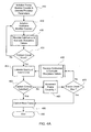
- Figure 4A is a flow diagram showing selected steps of an embodiment for improved image capture.
- Figure 4B is a flow diagram showing some further details of selected steps of the embodiment in Figure 4A.
- Figure 5 illustrates the movement of pixel data in line buffers of an embodiment.
- Figure 6 is a flow diagram showing data flow of an embodiment for improved image capture.
- Figure 7 is a graph illustrating improved image capture of an embodiment.
- Figure 8 illustrates an embodiment of a digital camera.
- a system, method and apparatus are provided for image anti-shake in digital still cameras.
- the specific embodiments described in this document represent exemplary instances of the present invention, and are illustrative in nature rather than restrictive.
- a method of capturing an image in a digital camera includes calculating a sharpness value based on an image input.
- calculating the sharpness value comprises determining a high frequency value related to the image input.
- the method also includes predicting the quality of a next image based on the sharpness value.
- the method further includes deciding whether to capture a next image input data responsive to the prediction.
- a digital camera in another embodiment, is presented.
- the camera includes a processor.
- the camera also includes media for image storage coupled to the processor.
- the camera further includes an image sensor coupled to the processor.
- the camera includes an image quality detector for detecting image motion.
- the image quality detector includes a sharpness detector based on high pass filtering of image data from the digital image sensor.
- the camera includes a predictor of next image motion coupled to the quality detector.
- the camera includes a decision maker coupled to the predictor.
- the predictor and decision maker are to evaluate output of the quality detector and capture an image from the digital image sensor in the media, responsive to the output of the quality detector.
- the quality detector, the predictor and the decision maker can be implemented by the processor in some embodiments.
- an apparatus in another embodiment, includes means for calculating a sharpness value related to a current image input.
- the apparatus also includes means for estimating next image quality depending on the sharpness value.
- the apparatus further includes means for capturing a next image input data frame from the image input. The means for capturing operates responsive to the means for estimating next image quality.
- a method and apparatus as described and illustrated can improve image quality in digital still cameras.
- the method and apparatus depend on evaluating motion characteristics of image input data, and then capturing the next image sensed.
- the process can then capture the next image with the expectation that the next image will be relatively stable. This allows for rapid evaluation, without the need to store multiple images. It also reduces cost associated with expensive components such a movable image sensors and lenses, for example.
- Figure 1 illustrates an embodiment of a system for reducing the effects of image motion in a digital camera.
- System 100 includes optical components 105 that project an image onto an image sensor 110.
- the image sensor may be a CCD, CMOS or similar image sensor matrix array.
- the array is a rectangular array of detectors arranged in rows and columns. Pixels of the image sensor 110 are exposed according to a rolling shutter timing mechanism which is well known in the art.
- a first row of pixels is selected and the image data from individual pixels in the selected row are output sequentially from the image sensor into a line buffer 150. Next, a following row is copied from the image output to the line buffer in the same manner.
- a blanking period of predetermined time occurs before the raster scan is repeated.
- the set of image data of a complete scan from each and every pixel in the image sensor 110 is termed a frame. It is seen that the image sensor is operable to output image data responsive to the projected image.
- an artificial frame consisting of selected submatrices of image sensor pixel data can be repeatedly scanned in a selected order.
- a sensor comprising a pixel addressable image buffer is operable to implement aspects of the invention.
- the invention includes an efficient camera anti-shake method that includes evaluating relative sharpness changes based on the subframes, and predicting the sharpness of a next image based on the relative changes.
- the camera anti-shake method is operable to reduce the adverse effects of subject motion on image quality.
- an anti-shake digital camera using the anti-shake method is disclosed. The digital camera is easily implemented with modest hardware resources, resulting in relatively low cost.
- the system 100 includes an image sensor 110 that forms image data responsive to an image from the optical path 105. Although the image is of visible light in this embodiment, other embodiments comprise imaging other forms of electromagnetic radiation such as infrared, x-rays, millimeter waves, and so forth.
- the system 100 further includes machine readable media operable to store instructions and data, and at least one processor operable to perform the instructions and operate on the data.
- the system also includes an image quality detector 120 that senses image motion based on image data input from the image sensor 110.
- data input from the image sensor 110 is moved into a buffer 150 of machine readable media.
- the buffer is coupled to the image quality detector 120.
- the quality detector 120 comprises a sharpness detector.
- the system 100 also includes a motion predictor 130 and a decision maker 140. Instructions and data in the computer readable media are operable by the processor to implement the sharpness detector 120, the predictor 130, and the decision maker 140. However in various other embodiments, functionality of the detector, predictor or decision maker, in whole or in part, can be implemented with control circuits.
- the media comprises line buffers operable for storing a number of lines of image data corresponding to rows of the pixel data input from the image sensor 110.
- lines of image data in the embodiment are rows of data
- lines which are columns of pixel data can equivalently be used in various embodiments.
- detectors comprising non-rectangular pixel configurations and/or other methods operable to receive an image input from an image sensor and store the data in the machine readable media are operable to practice the invention.
- the image sensor 110 is an XGA resolution sensor which has 768 rows comprising 1024 pixels in each row. Hence each full image frame of the sensor comprises 1024 x 768 pixels.
- an image frame comprising a subset of pixel data that is from the sensor is often selected for processing. For example, a smaller array of pixels containing the subject of interest can be selected, thus avoiding the overhead associated with processing and storing unwanted background from the image input (in some embodiments this is termed "digital zoom").
- an image frame is divided into four row-wise subframes.
- Each of the subframes is W pixels wide and H pixels high.
- W which is the number of horizontal pixels or columns in a row
- H is the number of pixel rows of the image frame divided by the number of subframes. Therefore the value of H in the embodiment is 256.
- W and H depend on the selected resolution and the selected number of subframes.
- the frame image acquisition rate is 15 or 30 frames per second, responsive to a number of design constraints and industry standards.
- the corresponding image frame exposure times will be somewhat less than 1/15s or 1/30s since the frame rate usually includes a blanking period between exposures.
- the successively numbered lines of an image frame are exposed sequentially.
- an image frame must be divided into more subframes in order to effectively sample relative motion of the image.
- the number of subframes is too high, the reduced height of each subframe can introduce an artificial sensitivity to motion in the vertical direction.
- the sharpness detector 110 detects a sharpness based on the spatial high frequency content of image data.
- images of objects have sharper edges (e.g. the objects are not blurred by camera shaking or transient subject movement), they tend to have more high frequency content. Images of the same object with motion tend to have less high frequency content (e.g. motion blur characteristically reduces edge definition).
- increased spatial high frequency content in an image correlates with sharpness. Therefore a high frequency extracting filter is useful for detecting the sharpness of an image.
- other methods of detecting sharpness, or conversely measures of the absence of sharpness are also useful to sense image motion, depending on the application.
- a sharpness detector comprises high pass filtering.
- the high pass filter matrix shown in Figure 3 is merely one example of a useful filter for extracting a high frequency portion of the image data. Matrices having a symmetry are particularly effective. Other high frequency extracting filters such as single bandpass filters or multiple bandpass filters in combination, and the like, are also useful in some embodiments, depending on the application.
- the predictor 130 estimates the expected image motion of a next frame based on the current subframe sharpness value of the current frame and previous subframe sharpness values of previous image frames.
- the predictor 130 estimates an image motion of the next image frame based on evaluating the two propositions:
- Proposition 2 D 4 j ⁇ 0 and
- k 1 and k 2 are selected factors. If at least one of these two propositions is true, a prediction that next frame image motion will be less than the current image frame motion is output to the decision module 140. Otherwise a prediction that the next frame image motion will be equal or greater than the current image frame motion is output to the decision maker. In practice, selecting a constant of 2/3 for k 1 and a constant of 1/2 for k 2 has been found to be quite effective. Other selections of k 1 and k 2 are operable, although it has been found that selecting values of k 1 and k 2 less than 1 is preferable.
- Proposition 1 and Proposition 2 in the embodiment are based on D 4 j since the data of subframe 4 are the last and most recent portion of image frame data input from the image sensor.
- Other methods of estimating motion based on the sharpness of the image frame data can be selected in various embodiments, and other predictors of future image motion can be used within the scope and spirit of the present invention.
- the decision module 140 calculates a frame sharpness, S j , of current frame j .
- other metrics of the frame sharpness based on other relationships are also operable, depending on the embodiment.
- the decision maker 140 decides whether or not to capture a next frame from the image sensor 110 and save it in an image memory 115. It will make a decision to capture when all of the following three propositions are true: 1) a capture command was received, 2) the predictor predicts that the next frame will have increased sharpness, and 3) S j > S c . (e.g. the current frame is sharper than the first image frame received after the capture command).
- the decision maker 140 in Figure 1 includes a timeout override for capturing the next image frame from the data sensor 110 through the buffer 150 and into image memory 115.
- the decision maker 140 decides to timeout and instructs a processor to perform image processing 160 and capture the next image frame from the image sensor 110 into image storage 170, corresponding to stepping through 460, 465, 470, and 480 in Figure 4A..
- the decision maker 140 does not decide to capture a next image
- another subframe of pixels is read from the image sensor 110 and processed by the quality detector 120 and the predictor 130.
- the scope and spirit of the present invention includes embodiments comprising other methods and/or algorithms for deciding whether to capture a next image based on an output of the predictor and the number of frames and/or time elapsed after a capture command.
- Figures 4A and 4B show further details of an embodiment for image evaluation and capturing.
- registers used to retain the quality detector and predictor parameters and variables e.g. D max ,S c ,s ij ,D ij etc.
- the frame number counter are initialized at box 410.
- a subframe number counter is initialized at box 420.
- the number of frames that are received depends on the cumulative total number of subframes that are received.
- counting functions are combined. Also, the counting comprising incrementing the frame counter 461, testing the frame counter 470, incrementing the subframe number 441 and resetting the subframe number 447 may be implemented in other ways including ways having fewer steps.
- the cumulative total number of subframes comprises the subframe number (the subframe number is equal to the cumulative total subframe number modulo 4), and the frame number (the frame number is integer part of the quotient of cumulative total subframe count divided by 4).
- a frame is acquired at box 430, subframe by subframe 442 as sharpness values of the subframes, sharpness value differences, and D max are evaluated and stored in registers 445.
- the sharpness values are evaluated according to the relationships set forth above.
- various other methods and measures of sharpness can be used for evaluating the quality of an image, including other measures depending on filtering a high frequency portion of the image.
- Each of the blocks 430 and 435 of Figure 4A comprises the steps enumerated in blocks 441 through 447 of Figure 4B.
- the subframe number is incremented 441
- a portion of subframe data is read from the image sensor 442, and terms depending on the subframe data are evaluated 442.
- Additional portions of the subframe are read and evaluated 442-444 until the processing of subframe is complete 445, and sharpness values characteristic of the subframe are evaluated and stored in processor readable media.
- These steps 441, 442, 444, 445 are repeated until the complete frame has been processed at block 446.
- the subframe number is reset 447.
- a frame is read and evaluated at 430, another frame is acquired and evaluated until a capture command is received 450.
- the predictor estimates the quality of the next frame 455 and evaluates capture criteria based on the estimated quality 460. If the capture criteria based on the estimated quality are met, the decision maker commands the capture of a next frame into an image memory 480 and the process ends 490. However, if the capture criteria based on the estimated quality are not met 460, the frame counter is incremented 461 and the decision maker tests whether the frame count has reached the predetermined maximum number "Max" 470. If the frame counter has reached Max, the decision maker commands the capture of a next frame into an image memory 480 and the process ends at block 490. Otherwise at block-435 another frame is acquired and evaluated.
- a buffer memory for storing pixel data to evaluate terms according to the methods of Figures 1 and 4 is illustrated in Figure 5.
- a relatively small line buffer 510 including memory for storing 4 lines of pixel memory and a small number of word registers are sufficient storage for implementing the sharpness detector 120, predictor 130 and decision maker 140 illustrated in Figure 1.
- the computational operations to evaluate the subframe sums s ij include accumulating the convolution terms g ( x , y ) as taught above.
- the terms are evaluated using the convolution matrix coefficients (shown in Figure 3), five columns of four consecutive lines (rows) of the current image subframe data 540 ( Figure 5), and a five column portion 530 ( Figure 5) comprising the image data of the current line most recently received from the image sensor.
- Figure 5 also illustrates pixel data movement when evaluating the convolution.
- An incoming pixel value 575, from a current line (the row being processed) of the current subframe, is received from the image sensor and stored in a rightmost cell 576 of a short logical five register buffer 530.
- Four other incoming pixel data of that line are stored adjacently in the register buffer, in order of being read in (least recent to the left, most recent going right).
- row segment 520 comprises columns of the current line (row) of data that were received from the image sensor into the five column pixel data register buffer 530.
- the pixel data in "window" 540 of the line buffers 510 and the short five column register buffer 530 are sufficient for evaluating one term of the convolution sum.
- the evaluation is by multiplying the elements of the 5 x 5 mask w ( m , n ) of Figure 3 with corresponding values f ( x + m , y + n ) stored in the dashed areas including five columns of the line buffers 540 and five column register buffer 530, and adding the signed products into an accumulation register thereby accumulating the 25 terms comprising g ( x,y ).
- the window of the line buffers and the most recently received pixel data are advanced to the right by one column to the position 550 as shown in the lower portion of Figure 5.
- the oldest datum at [ x -2, y -2] in window 540 of the top half of the figure is no longer needed for term evaluations. It is overwritten by the datum at [ x -2, y -1] (e.g. effectively discarded as depicted by arrow 561 and replaced by the data from the position below as depicted by arrow 562).
- each of the data in column x -2 of the four line buffer 510 is shifted up one row as depicted by the arrows 562, 564, and 566: the datum at [ x -2, y -1] is moved to position [ x -2, y -2] 562, the datum at [ x -2, y ] is moved to position [ x -2, y -1], the datum at [ x -2, y +1] is moved to [ x -1, y ] 564, and the oldest pixel data [ x -2, y +2] in leftmost position of the five column line buffer register as shown in 530, is transferred into position [ x -2, y +1] of the 4 line data buffer, depicted by arrow 568.
- the other values in the five column incoming pixel data buffer register 530 are left shifted by one column as depicted schematically by arrows 570, 571, 572, 573.
- next pixel datum received from the image sensor is then read into the rightmost column of buffer register 530.
- the next term, g ( x +1, y ) can then be evaluated as described for g ( x , y ) above.
- the process of evaluating a term of the convolution sum, shifting the pixel data positions, and advancing the window right one column is repeated until all of the terms in the row y of s ij have been accumulated.
- the window position is then restarted at the left and terms of the next row, row y +1, are evaluated and accumulated in the same way.
- the sum s ij is complete when all rows of subframe i have been processed.
- edge values can be estimated by standard techniques for a boundary (e.g. extrapolation, mirroring, assuming the value of the first available row, truncation, etc.).
- filtering is limited to the reduced subframe [ W- 2 ⁇ H- 2] so that physical row and column data from the image sensor are available to evaluate the terms.
- the numbering of the indices and constants for boundary values are adjusted accordingly using standard techniques.
- a line buffer for a relatively small number of lines and a small number of storage registers are sufficient for implementing the predictor 130 and decision maker 140.
- four sharpness values s ij characterize motion in the j th frame.
- the predictor in the embodiment depends on D max ,D 3 j ,D 4 j ,k 1 , and k 2 .
- the decision maker 140 depends on S j ,S c , predictor output, and the selected maximum number of frames. Hence the predictor and decision maker can be implemented using about 15 register cells for storing constants and values characteristic of the motion.
- filter convolution matrices that are larger or smaller than the illustrative 5x5 matrix.
- the number of line buffers operable to evaluate image sharpness is one less than the dimensionality of the convolution matrix (5 in the matrix embodiment of Figure 3).
- a small register buffer is required for storing a number of pixel data, the number being equal to the dimensionality of the filtering matrix.
- FIG. 6 illustrates simplified aspects of data flow in a digital camera embodiment of the invention.
- the camera has a processor 650.
- the camera also has machine readable media including storage for instructions and data operable by the processor to implement a control program 640, instructions to implement a quality detector, predictor and decision maker 630, data storage for filter coefficients to implement a high frequency sharpness filter 620, data storage for selected constants to implement other functions including the quality detector, predictor and decision maker, and data storage registers for storing and receiving values and results by the processor.
- the camera has an image sensor. Responsive to an image, the image sensor sequentially sends image sensor pixel data 610 comprising lines of image sensor pixels to line buffers 670.
- the processor 650 has no direct access to the data in line buffers 670.
- Control circuitry automatically mirrors a portion of the line buffers 670 into mirror registers 660.
- the mirror registers 660 are interrogated by the processor.
- the mirrored data portion 660 includes the matrix of the pixel data, including the data in storage 540 and 530 for evaluating s ij as described in connection with Figure 5.
- the camera also includes an image signal processor (ISP) 680 for processing pixel data 610 from a register 675 of the media, and transforming the pixel data into another form, such as compressed Joint Photographic Experts Group form (JPEG), for capturing and storing in a picture storage media 695.
- ISP image signal processor
- JPEG compressed Joint Photographic Experts Group form
- control program in media 640 directs operation and data flow between the program modules of the quality detector, predictor and decision maker according to the method of Figure 4.
- the processor performs the quality detector, accessing filter matrix coefficients and constants stored in media 620, and saves results in register media 665. Selected constants of the predictor and decision maker are also in media 620.
- the evaluated quantities based on the image data e.g. g ( x,y ) ,s ij ,D max etc.
- the decision maker decides to capture a next image, it outputs a capture signal on signal line 665 to gating control circuitry 690.
- the gating control 690 captures a next image from the ISP into the picture storage 695 if and only the decision maker outputs the capture signal.
- the quality detector, predictor and decision maker are implemented by a processor operable to perform program code in the embodiment, in other embodiments various of these functions or all of these functions are implemented using control circuitry. Also, although the mirror registers 660 and quality detector in 630 of the embodiment detect image quality based on high a 5x5 matrix high pass filtering of the image data, in various other embodiments a quality detector is implemented based on wavelet transforms, or various other methods adapted to detect sharpness, depending on the application.
- the left hand vertical axis 722 for S j and the right hand vertical axis 724 for D ij are marked in arbitrary units.
- the sharpness 781 of image frame 1 is about 167 units.
- the illustrative camera in the embodiment corresponding to Figure 7 has a preset frame timeout parameter of 10 frames.
- image frame 1 After the evaluation of image frame 1 four more image frames are read and evaluated.
- a capture command is received just after processing the 20 th subframe 735.
- the 10 th image frame after the capture command is image frame 15 at 796 in Figure 7. This is the image frame where the timeout maximum of 10 frames after the capture command is reached. Therefore the decision maker will not make a decision to capture based on a timeout override until after image frame 14 (subframe 56 at 738) has been evaluated.
- D max is first determined by selecting the maximum value of
- the Proposition 2 is true and the predictor predicts that the next image motion will be less than the current image frame motion.
- Figure 8 shows one example of a personal device that can be used as a digital camera or similar device.
- a device can be used to perform many functions, depending on implementation, such as telephone communications, two-way pager communications, personal organizing, global positioning system, or similar functions.
- the computer system 800 represents the computer portion of the device comprising a digital camera.
- the computer 800 interfaces to external systems through the communications interface 820.
- This interface is typically some form of cable and/or wireless interface for use with an immediately available personal computer, and may include a radio interface for communication with a network such as an 802.11 wireless network.
- a network such as an 802.11 wireless network.
- various networks and communication methods such as a Bluetooth, an infrared optical interface, a cellular telephone interface and others, depending on the application.
- the computer system 800 includes a processor 810, which can be a conventional microprocessor such as an Intel Pentium microprocessor, an IBM power PC microprocessor, a Texas Instruments digital signal processor, or some combination of various types of processors, depending on the embodiment.
- Memory 840 is coupled to the processor 810 by a bus 870.
- Memory 840 can be dynamic random access memory (DRAM) and can also include static ram (SRAM), flash memory, magnetic memory (MRAM) and other types, depending on the application.
- the bus 870 couples the processor 810 to the memory 840, also to non-volatile storage 850, to display controller 830, and to the input/output (I/O) controller 860.
- various combinations of these components are integrated in a single integrated circuit or in a combination of integrated circuits that are combined into a single package.
- the display controller 830 and I/O controller 860 are often be integrated together, and the display may also provide input.
- the display controller 830 controls in the conventional manner of a display controller on a display device 835 which typically is a liquid crystal display (LCD) or similar flat-panel, small form factor display.
- the input/output devices 855 can include a keyboard, or stylus and touch-screen, and may sometimes be extended to include disk drives, printers, a scanner, and other input and output devices, including a mouse or other pointing device, such as when a camera is connected to some form of docking station or personal computer.
- the display controller 830 and the I/O controller 860 can be implemented with conventional well known technology.
- a digital image input device 865 can be a digital camera comprising an embodiment of the invention which is coupled to an I/O controller 860 or through a separate coupling in order to allow images to be input into the device 800.
- the non-volatile storage 850 is often a FLASH memory or read-only memory, or some combination of the two.
- a magnetic hard disk, an optical disk, or another form of storage for large amounts of data may also be used in some embodiments, though the form factors for such devices typically preclude installation as a permanent component of the device 800. Rather, a mass storage device on another computer is typically used in conjunction with the more limited storage of the device 800. Some of this data is often written, by a direct memory access process, into memory 840 during execution of software in the device 800.
- machine-readable medium or “computer-readable medium” include any type of storage device that is accessible by the processor 810 and also encompasses a carrier wave that encodes a data signal.
- the device 800 is one example of many possible devices which have different architectures.
- devices based on an Intel microprocessor often have multiple buses, one of which can be an input/output (I/O) bus for the peripherals and one that directly connects the processor 810 and the memory 840 (often referred to as a memory bus).
- the buses are connected together through bridge components that perform any necessary translation due to differing bus protocols.
- the device 800 is controlled by operating system software which may include a file management system, such as a disk operating system, which is part of the operating system software.
- a file management system such as a disk operating system
- One example of an operating system with its associated file management system software is the family of operating systems known as Windows CE® from Microsoft Corporation of Redmond, Washington, and their associated file management systems.
- Another example of an operating system with its associated file management system software is the Palm® operating system and its associated file management system.
- the file management system is typically stored in the non-volatile storage 850 and causes the processor 810 to execute the various acts required by the operating system to input and output data and to store data in memory, including storing files on the non-volatile storage 850.
- Other operating systems may be provided by makers of devices, and those operating systems typically will have device-specific features which are not part of similar operating systems on similar devices.
- WinCE® or Palm® operating systems may be adapted to specific devices for specific device capabilities.
- Device 800 may be integrated onto a single chip or set of chips in some embodiments, and typically is fitted into a small form factor for use as a personal device. Thus, it is not uncommon for a processor, bus, onboard memory, and display-I/O controllers to all be integrated onto a single chip. Alternatively, functions may be split into several chips with point-to-point interconnection, causing the bus to be logically apparent but not physically obvious from inspection of either the actual device or related schematics.
Landscapes
- Engineering & Computer Science (AREA)
- Multimedia (AREA)
- Signal Processing (AREA)
- Studio Devices (AREA)
- Image Processing (AREA)
- Adjustment Of Camera Lenses (AREA)
- Closed-Circuit Television Systems (AREA)
- Ultra Sonic Daignosis Equipment (AREA)
- Exposure Control For Cameras (AREA)
Applications Claiming Priority (2)
| Application Number | Priority Date | Filing Date | Title |
|---|---|---|---|
| US76351606P | 2006-01-30 | 2006-01-30 | |
| US11/395,282 US7593040B2 (en) | 2006-01-30 | 2006-03-31 | Image anti-shake in digital cameras |
Publications (2)
| Publication Number | Publication Date |
|---|---|
| EP1814317A1 true EP1814317A1 (de) | 2007-08-01 |
| EP1814317B1 EP1814317B1 (de) | 2011-03-09 |
Family
ID=37888170
Family Applications (1)
| Application Number | Title | Priority Date | Filing Date |
|---|---|---|---|
| EP07250112A Active EP1814317B1 (de) | 2006-01-30 | 2007-01-11 | Verminderung des Verwackelns von Bildern in digitale Kameras |
Country Status (5)
| Country | Link |
|---|---|
| US (1) | US7593040B2 (de) |
| EP (1) | EP1814317B1 (de) |
| AT (1) | ATE501593T1 (de) |
| DE (1) | DE602007012949D1 (de) |
| TW (1) | TWI339986B (de) |
Families Citing this family (17)
| Publication number | Priority date | Publication date | Assignee | Title |
|---|---|---|---|---|
| US7352390B2 (en) * | 2003-10-08 | 2008-04-01 | Hewlett-Packard Development Company, L.P. | Digital camera for capturing image data with rapid response between activating a capture trigger and capturing image data |
| JP4636979B2 (ja) * | 2005-09-09 | 2011-02-23 | キヤノン株式会社 | 撮像装置及びその制御方法 |
| JP4969182B2 (ja) * | 2006-08-28 | 2012-07-04 | 富士フイルム株式会社 | 手振れ量検出装置及び撮影装置 |
| DE102007034608A1 (de) * | 2007-07-25 | 2009-01-29 | Robert Bosch Gmbh | Kamera |
| US9179060B2 (en) * | 2007-09-27 | 2015-11-03 | Qualcomm Incorporated | Method and apparatus for camera shake effect image stabilization |
| JP5164532B2 (ja) * | 2007-11-14 | 2013-03-21 | オンセミコンダクター・トレーディング・リミテッド | 半導体モジュールおよび撮像装置 |
| JP5164533B2 (ja) * | 2007-11-14 | 2013-03-21 | オンセミコンダクター・トレーディング・リミテッド | 半導体モジュールおよび撮像装置 |
| KR101003568B1 (ko) * | 2007-11-14 | 2010-12-22 | 산요 세미컨덕터 컴퍼니 리미티드 | 반도체 모듈 및 촬상 장치 |
| US20090174674A1 (en) * | 2008-01-09 | 2009-07-09 | Qualcomm Incorporated | Apparatus and methods for a touch user interface using an image sensor |
| JP5226352B2 (ja) * | 2008-03-21 | 2013-07-03 | オリンパス株式会社 | 生体観察装置及び生体観察方法 |
| US20110109752A1 (en) * | 2009-11-11 | 2011-05-12 | Omnivision Technologies, Inc. | Image sensor with shaking compensation |
| KR101630307B1 (ko) * | 2010-05-12 | 2016-06-14 | 삼성전자주식회사 | 디지털 촬영 장치, 그 제어 방법, 및 컴퓨터 판독가능 저장매체 |
| US8692900B2 (en) * | 2011-04-22 | 2014-04-08 | Blackberry Limited | Frame selection to provide for a zero shutter lag in a digital camera |
| US9635287B2 (en) | 2011-10-11 | 2017-04-25 | Raytheon Company | Method and apparatus for integrated sensor to provide higher resolution, lower frame rate and lower resolution, higher frame rate imagery simultaneously |
| CN104168814B (zh) * | 2012-03-28 | 2016-08-17 | 富士胶片株式会社 | 摄像装置以及具备该摄像装置的内窥镜装置 |
| US11431941B2 (en) | 2018-06-12 | 2022-08-30 | Carl Zeiss Ag | Method, apparatus, and system for processing digital images |
| US10681266B2 (en) * | 2018-06-12 | 2020-06-09 | Carl Zeiss Ag | Method, apparatus, and system for processing digital images |
Citations (4)
| Publication number | Priority date | Publication date | Assignee | Title |
|---|---|---|---|---|
| JPH08320511A (ja) * | 1995-05-24 | 1996-12-03 | Olympus Optical Co Ltd | ぶれ低減カメラ |
| US20030193610A1 (en) * | 1998-08-21 | 2003-10-16 | Hirotake Nozaki | Electronic camera |
| US20040239795A1 (en) * | 2003-03-20 | 2004-12-02 | Tatsutoshi Kitajima | Digital camera |
| US20050219666A1 (en) * | 1998-11-20 | 2005-10-06 | Nikon Corporation | Image processing apparatus having image selection function, and recording medium having image selection function program |
Family Cites Families (50)
| Publication number | Priority date | Publication date | Assignee | Title |
|---|---|---|---|---|
| US5701522A (en) | 1991-03-06 | 1997-12-23 | Nikon Corporation | Camera shake amplitude detecting device |
| US5416558A (en) | 1991-10-16 | 1995-05-16 | Nikon Corporation | Camera with shake preventing apparatus |
| US5463443A (en) | 1992-03-06 | 1995-10-31 | Nikon Corporation | Camera for preventing camera shake |
| US5712474A (en) | 1993-09-29 | 1998-01-27 | Canon Kabushiki Kaisha | Image processing apparatus for correcting blurring of an image photographed by a video camera |
| JPH07199066A (ja) | 1993-12-28 | 1995-08-04 | Nikon Corp | 大口径中望遠レンズ |
| US5790490A (en) | 1996-05-10 | 1998-08-04 | Olympus Optical Co., Ltd. | Anti-shake camera |
| JPH10232132A (ja) | 1997-02-20 | 1998-09-02 | Murata Mfg Co Ltd | 振動ジャイロ |
| JP3963568B2 (ja) | 1997-05-28 | 2007-08-22 | オリンパス株式会社 | カメラの自動焦点調節装置 |
| US6982746B1 (en) | 1998-02-24 | 2006-01-03 | Canon Kabushiki Kaisha | Apparatus and method for correcting shake by controlling sampling timing of shake signal |
| US6630950B1 (en) | 1998-03-19 | 2003-10-07 | Canon Kabushiki Kaisha | Apparatus for improving image vibration suppression |
| JP2000180911A (ja) | 1998-12-15 | 2000-06-30 | Canon Inc | 像振れ補正装置 |
| US6464363B1 (en) | 1999-03-17 | 2002-10-15 | Olympus Optical Co., Ltd. | Variable mirror, optical apparatus and decentered optical system which include variable mirror, variable-optical characteristic optical element or combination thereof |
| US6487369B1 (en) | 1999-04-26 | 2002-11-26 | Olympus Optical Co., Ltd. | Camera with blur reducing function |
| JP2003075618A (ja) | 2001-09-05 | 2003-03-12 | Olympus Optical Co Ltd | 可変ミラー及びそれを用いた光学装置 |
| US7791641B2 (en) | 2001-09-12 | 2010-09-07 | Samsung Electronics Co., Ltd. | Systems and methods for utilizing activity detection information in relation to image processing |
| JP4138324B2 (ja) | 2001-11-28 | 2008-08-27 | 松下電器産業株式会社 | ズームレンズ及びそれを用いたビデオカメラ |
| JP4072348B2 (ja) * | 2002-01-25 | 2008-04-09 | キヤノン株式会社 | 振れ補正装置、撮像装置、振れ補正方法、振れ補正装置の制御プログラム、及び記憶媒体 |
| US6999241B2 (en) | 2002-02-25 | 2006-02-14 | Matsushita Electric Industrial Co., Ltd. | Zoom lens, and video camera and digital still camera using the zoom lens |
| US7492408B2 (en) | 2002-05-17 | 2009-02-17 | Olympus Corporation | Electronic imaging apparatus with anti-dust function |
| JP4423889B2 (ja) | 2002-11-18 | 2010-03-03 | ソニー株式会社 | フリッカ低減方法、撮像装置およびフリッカ低減回路 |
| JP2004266709A (ja) | 2003-03-04 | 2004-09-24 | Victor Co Of Japan Ltd | 撮像装置 |
| US7525572B2 (en) | 2003-03-28 | 2009-04-28 | Victor Company Of Japan, Ltd. | Video camera with anti-shake system |
| US7420606B2 (en) | 2003-07-16 | 2008-09-02 | Matsushita Electric Industrial Co., Ltd. | Timing generator, solid-state imaging device and camera system |
| JP4328573B2 (ja) | 2003-08-07 | 2009-09-09 | キヤノン株式会社 | 振れ補正装置及びその制御方法 |
| JP2005128186A (ja) | 2003-10-22 | 2005-05-19 | Matsushita Electric Ind Co Ltd | ズームレンズ、並びにそれを用いたビデオカメラ及びデジタルスチルカメラ |
| US20050168585A1 (en) | 2004-01-30 | 2005-08-04 | Pentax Corporation | Anti-shake apparatus |
| US7355630B2 (en) | 2004-01-30 | 2008-04-08 | Pentax Corporation | Anti-shake apparatus with position detecting magnet |
| JP4540354B2 (ja) | 2004-01-30 | 2010-09-08 | Hoya株式会社 | 像ブレ補正装置 |
| JP4497946B2 (ja) | 2004-02-03 | 2010-07-07 | キヤノン株式会社 | 撮像装置 |
| US7405750B2 (en) | 2004-02-27 | 2008-07-29 | Hoya Corporation | Position-detecting apparatus |
| JP2005244725A (ja) | 2004-02-27 | 2005-09-08 | Pentax Corp | 像ブレ補正装置 |
| US7502051B2 (en) | 2004-03-08 | 2009-03-10 | Hoya Corporation | Anti-shake apparatus |
| US7598981B2 (en) | 2004-03-08 | 2009-10-06 | Hoya Corporation | Anti-shake apparatus |
| US7495693B2 (en) | 2004-03-08 | 2009-02-24 | Hoya Corporation | Anti-shake apparatus |
| US7224893B2 (en) | 2004-03-08 | 2007-05-29 | Pentax Corporation | Anti-shake apparatus |
| US7453494B2 (en) | 2004-03-09 | 2008-11-18 | Hoya Corporation | Anti-shake apparatus having magnetic position detectors positioned on one axis with common input circuitry |
| JP4530691B2 (ja) | 2004-03-17 | 2010-08-25 | Hoya株式会社 | 像ブレ補正装置 |
| JP2005283965A (ja) | 2004-03-30 | 2005-10-13 | Pentax Corp | ブレ量表示装置 |
| US7561186B2 (en) * | 2004-04-19 | 2009-07-14 | Seiko Epson Corporation | Motion blur correction |
| US7295770B2 (en) | 2004-04-20 | 2007-11-13 | Pentax Corporation | Anti-shake apparatus |
| JP2005316222A (ja) | 2004-04-30 | 2005-11-10 | Pentax Corp | 像ブレ補正装置 |
| US7742076B2 (en) | 2004-05-25 | 2010-06-22 | Hoya Corporation | Image-capturing apparatus and camera-shake compensation mechanism |
| US7440686B2 (en) | 2004-05-31 | 2008-10-21 | Hoya Corporation | Anti-shake apparatus |
| JP4691326B2 (ja) | 2004-06-08 | 2011-06-01 | Hoya株式会社 | 像ブレ補正装置 |
| US7586518B2 (en) | 2004-06-18 | 2009-09-08 | Canon Kabushiki Kaisha | Imaging technique performing focusing on plurality of images |
| TWI422957B (zh) | 2004-06-23 | 2014-01-11 | Pentax Ricoh Imaging Co Ltd | 照相設備 |
| TWI375112B (en) | 2004-06-24 | 2012-10-21 | Pentax Ricoh Imaging Co Ltd | Digital camera |
| US7742515B2 (en) | 2004-06-25 | 2010-06-22 | Finisar Corporation | Vertical cavity surface emitting laser optimized for optical sensitivity |
| US7848595B2 (en) | 2004-06-28 | 2010-12-07 | Inphase Technologies, Inc. | Processing data pixels in a holographic data storage system |
| JP4390274B2 (ja) * | 2004-12-27 | 2009-12-24 | キヤノン株式会社 | 撮像装置及び制御方法 |
-
2006
- 2006-03-31 US US11/395,282 patent/US7593040B2/en active Active
-
2007
- 2007-01-10 TW TW096101013A patent/TWI339986B/zh active
- 2007-01-11 DE DE602007012949T patent/DE602007012949D1/de active Active
- 2007-01-11 AT AT07250112T patent/ATE501593T1/de not_active IP Right Cessation
- 2007-01-11 EP EP07250112A patent/EP1814317B1/de active Active
Patent Citations (4)
| Publication number | Priority date | Publication date | Assignee | Title |
|---|---|---|---|---|
| JPH08320511A (ja) * | 1995-05-24 | 1996-12-03 | Olympus Optical Co Ltd | ぶれ低減カメラ |
| US20030193610A1 (en) * | 1998-08-21 | 2003-10-16 | Hirotake Nozaki | Electronic camera |
| US20050219666A1 (en) * | 1998-11-20 | 2005-10-06 | Nikon Corporation | Image processing apparatus having image selection function, and recording medium having image selection function program |
| US20040239795A1 (en) * | 2003-03-20 | 2004-12-02 | Tatsutoshi Kitajima | Digital camera |
Also Published As
| Publication number | Publication date |
|---|---|
| TWI339986B (en) | 2011-04-01 |
| TW200733726A (en) | 2007-09-01 |
| US7593040B2 (en) | 2009-09-22 |
| EP1814317B1 (de) | 2011-03-09 |
| US20070177021A1 (en) | 2007-08-02 |
| DE602007012949D1 (de) | 2011-04-21 |
| ATE501593T1 (de) | 2011-03-15 |
Similar Documents
| Publication | Publication Date | Title |
|---|---|---|
| EP1814317B1 (de) | Verminderung des Verwackelns von Bildern in digitale Kameras | |
| US10007990B2 (en) | Generating composite images using estimated blur kernel size | |
| US8600187B2 (en) | Image restoration apparatus and image restoration method | |
| JP4956401B2 (ja) | 撮像装置及びその制御方法及びプログラム | |
| EP2403235B1 (de) | Bildkorrekturvorrichtung und bildkorrekturverfahren | |
| US20020167597A1 (en) | Image restoration apparatus by the iteration method | |
| EP2048878A1 (de) | Bilderzeugungsvorrichtung, bilderzeugungsverfahren und entsprechendes programm | |
| US7355643B2 (en) | Image pickup device | |
| EP2126627B1 (de) | Verfahren zur verbesserung der videobilder einer videokamera | |
| JP2021530770A (ja) | ビデオ処理方法、装置及びコンピュータ記憶媒体 | |
| US7705885B2 (en) | Image and video motion stabilization system | |
| CN103634513A (zh) | 图像处理设备及其控制方法 | |
| US20100061650A1 (en) | Method And Apparatus For Providing A Variable Filter Size For Providing Image Effects | |
| US20120019677A1 (en) | Image stabilization in a digital camera | |
| US20070127902A1 (en) | Avoiding image artifacts caused by camera vibration | |
| US6906754B1 (en) | Electronic display with compensation for shaking | |
| US20090086036A1 (en) | Method and apparatus for camera shake effect image stabilization | |
| US7466862B2 (en) | Image expansion and display method, image expansion and display device, and program for image expansion and display | |
| JP2007243335A (ja) | 手振れ補正方法、手振れ補正装置および撮像装置 | |
| US7778475B2 (en) | Motion picture processing device | |
| US20080310751A1 (en) | Method And Apparatus For Providing A Variable Blur | |
| US7864214B2 (en) | Signal processing device | |
| CN101159813B (zh) | 数码相机中的图像防颤的方法及装置 | |
| JPH0795469A (ja) | カムコーダの映像補正装置 | |
| US12445748B2 (en) | Image signal processor and imaging system including the same |
Legal Events
| Date | Code | Title | Description |
|---|---|---|---|
| PUAI | Public reference made under article 153(3) epc to a published international application that has entered the european phase |
Free format text: ORIGINAL CODE: 0009012 |
|
| 17P | Request for examination filed |
Effective date: 20070131 |
|
| AK | Designated contracting states |
Kind code of ref document: A1 Designated state(s): AT BE BG CH CY CZ DE DK EE ES FI FR GB GR HU IE IS IT LI LT LU LV MC NL PL PT RO SE SI SK TR |
|
| AX | Request for extension of the european patent |
Extension state: AL BA HR MK YU |
|
| 17Q | First examination report despatched |
Effective date: 20080214 |
|
| AKX | Designation fees paid |
Designated state(s): AT BE BG CH CY CZ DE DK EE ES FI FR GB GR HU IE IS IT LI LT LU LV MC NL PL PT RO SE SI SK TR |
|
| GRAP | Despatch of communication of intention to grant a patent |
Free format text: ORIGINAL CODE: EPIDOSNIGR1 |
|
| RIN1 | Information on inventor provided before grant (corrected) |
Inventor name: FLAMM, DANIEL L. Inventor name: PAN, HUI Inventor name: SHAN, JIZHANG Inventor name: LEE, JESS JAN YOUNG Inventor name: LIU, GUANSONG |
|
| GRAS | Grant fee paid |
Free format text: ORIGINAL CODE: EPIDOSNIGR3 |
|
| GRAA | (expected) grant |
Free format text: ORIGINAL CODE: 0009210 |
|
| AK | Designated contracting states |
Kind code of ref document: B1 Designated state(s): AT BE BG CH CY CZ DE DK EE ES FI FR GB GR HU IE IS IT LI LT LU LV MC NL PL PT RO SE SI SK TR |
|
| REG | Reference to a national code |
Ref country code: GB Ref legal event code: FG4D |
|
| REG | Reference to a national code |
Ref country code: CH Ref legal event code: EP |
|
| REG | Reference to a national code |
Ref country code: IE Ref legal event code: FG4D |
|
| REF | Corresponds to: |
Ref document number: 602007012949 Country of ref document: DE Date of ref document: 20110421 Kind code of ref document: P |
|
| REG | Reference to a national code |
Ref country code: DE Ref legal event code: R096 Ref document number: 602007012949 Country of ref document: DE Effective date: 20110421 |
|
| REG | Reference to a national code |
Ref country code: NL Ref legal event code: VDEP Effective date: 20110309 |
|
| PG25 | Lapsed in a contracting state [announced via postgrant information from national office to epo] |
Ref country code: ES Free format text: LAPSE BECAUSE OF FAILURE TO SUBMIT A TRANSLATION OF THE DESCRIPTION OR TO PAY THE FEE WITHIN THE PRESCRIBED TIME-LIMIT Effective date: 20110620 Ref country code: GR Free format text: LAPSE BECAUSE OF FAILURE TO SUBMIT A TRANSLATION OF THE DESCRIPTION OR TO PAY THE FEE WITHIN THE PRESCRIBED TIME-LIMIT Effective date: 20110610 Ref country code: LT Free format text: LAPSE BECAUSE OF FAILURE TO SUBMIT A TRANSLATION OF THE DESCRIPTION OR TO PAY THE FEE WITHIN THE PRESCRIBED TIME-LIMIT Effective date: 20110309 Ref country code: LV Free format text: LAPSE BECAUSE OF FAILURE TO SUBMIT A TRANSLATION OF THE DESCRIPTION OR TO PAY THE FEE WITHIN THE PRESCRIBED TIME-LIMIT Effective date: 20110309 Ref country code: SE Free format text: LAPSE BECAUSE OF FAILURE TO SUBMIT A TRANSLATION OF THE DESCRIPTION OR TO PAY THE FEE WITHIN THE PRESCRIBED TIME-LIMIT Effective date: 20110309 |
|
| LTIE | Lt: invalidation of european patent or patent extension |
Effective date: 20110309 |
|
| PG25 | Lapsed in a contracting state [announced via postgrant information from national office to epo] |
Ref country code: CY Free format text: LAPSE BECAUSE OF FAILURE TO SUBMIT A TRANSLATION OF THE DESCRIPTION OR TO PAY THE FEE WITHIN THE PRESCRIBED TIME-LIMIT Effective date: 20110309 Ref country code: SI Free format text: LAPSE BECAUSE OF FAILURE TO SUBMIT A TRANSLATION OF THE DESCRIPTION OR TO PAY THE FEE WITHIN THE PRESCRIBED TIME-LIMIT Effective date: 20110309 Ref country code: AT Free format text: LAPSE BECAUSE OF FAILURE TO SUBMIT A TRANSLATION OF THE DESCRIPTION OR TO PAY THE FEE WITHIN THE PRESCRIBED TIME-LIMIT Effective date: 20110309 Ref country code: BG Free format text: LAPSE BECAUSE OF FAILURE TO SUBMIT A TRANSLATION OF THE DESCRIPTION OR TO PAY THE FEE WITHIN THE PRESCRIBED TIME-LIMIT Effective date: 20110609 Ref country code: NL Free format text: LAPSE BECAUSE OF FAILURE TO SUBMIT A TRANSLATION OF THE DESCRIPTION OR TO PAY THE FEE WITHIN THE PRESCRIBED TIME-LIMIT Effective date: 20110309 |
|
| PG25 | Lapsed in a contracting state [announced via postgrant information from national office to epo] |
Ref country code: BE Free format text: LAPSE BECAUSE OF FAILURE TO SUBMIT A TRANSLATION OF THE DESCRIPTION OR TO PAY THE FEE WITHIN THE PRESCRIBED TIME-LIMIT Effective date: 20110309 |
|
| PG25 | Lapsed in a contracting state [announced via postgrant information from national office to epo] |
Ref country code: EE Free format text: LAPSE BECAUSE OF FAILURE TO SUBMIT A TRANSLATION OF THE DESCRIPTION OR TO PAY THE FEE WITHIN THE PRESCRIBED TIME-LIMIT Effective date: 20110309 Ref country code: PT Free format text: LAPSE BECAUSE OF FAILURE TO SUBMIT A TRANSLATION OF THE DESCRIPTION OR TO PAY THE FEE WITHIN THE PRESCRIBED TIME-LIMIT Effective date: 20110711 |
|
| PG25 | Lapsed in a contracting state [announced via postgrant information from national office to epo] |
Ref country code: SK Free format text: LAPSE BECAUSE OF FAILURE TO SUBMIT A TRANSLATION OF THE DESCRIPTION OR TO PAY THE FEE WITHIN THE PRESCRIBED TIME-LIMIT Effective date: 20110309 Ref country code: RO Free format text: LAPSE BECAUSE OF FAILURE TO SUBMIT A TRANSLATION OF THE DESCRIPTION OR TO PAY THE FEE WITHIN THE PRESCRIBED TIME-LIMIT Effective date: 20110309 Ref country code: CZ Free format text: LAPSE BECAUSE OF FAILURE TO SUBMIT A TRANSLATION OF THE DESCRIPTION OR TO PAY THE FEE WITHIN THE PRESCRIBED TIME-LIMIT Effective date: 20110309 Ref country code: IS Free format text: LAPSE BECAUSE OF FAILURE TO SUBMIT A TRANSLATION OF THE DESCRIPTION OR TO PAY THE FEE WITHIN THE PRESCRIBED TIME-LIMIT Effective date: 20110709 |
|
| PLBE | No opposition filed within time limit |
Free format text: ORIGINAL CODE: 0009261 |
|
| STAA | Information on the status of an ep patent application or granted ep patent |
Free format text: STATUS: NO OPPOSITION FILED WITHIN TIME LIMIT |
|
| 26N | No opposition filed |
Effective date: 20111212 |
|
| PG25 | Lapsed in a contracting state [announced via postgrant information from national office to epo] |
Ref country code: DK Free format text: LAPSE BECAUSE OF FAILURE TO SUBMIT A TRANSLATION OF THE DESCRIPTION OR TO PAY THE FEE WITHIN THE PRESCRIBED TIME-LIMIT Effective date: 20110309 Ref country code: PL Free format text: LAPSE BECAUSE OF FAILURE TO SUBMIT A TRANSLATION OF THE DESCRIPTION OR TO PAY THE FEE WITHIN THE PRESCRIBED TIME-LIMIT Effective date: 20110309 |
|
| REG | Reference to a national code |
Ref country code: DE Ref legal event code: R097 Ref document number: 602007012949 Country of ref document: DE Effective date: 20111212 |
|
| PG25 | Lapsed in a contracting state [announced via postgrant information from national office to epo] |
Ref country code: IT Free format text: LAPSE BECAUSE OF FAILURE TO SUBMIT A TRANSLATION OF THE DESCRIPTION OR TO PAY THE FEE WITHIN THE PRESCRIBED TIME-LIMIT Effective date: 20110309 |
|
| PG25 | Lapsed in a contracting state [announced via postgrant information from national office to epo] |
Ref country code: MC Free format text: LAPSE BECAUSE OF NON-PAYMENT OF DUE FEES Effective date: 20120131 |
|
| REG | Reference to a national code |
Ref country code: CH Ref legal event code: PL |
|
| REG | Reference to a national code |
Ref country code: IE Ref legal event code: MM4A |
|
| PG25 | Lapsed in a contracting state [announced via postgrant information from national office to epo] |
Ref country code: LI Free format text: LAPSE BECAUSE OF NON-PAYMENT OF DUE FEES Effective date: 20120131 Ref country code: CH Free format text: LAPSE BECAUSE OF NON-PAYMENT OF DUE FEES Effective date: 20120131 |
|
| PG25 | Lapsed in a contracting state [announced via postgrant information from national office to epo] |
Ref country code: IE Free format text: LAPSE BECAUSE OF NON-PAYMENT OF DUE FEES Effective date: 20120111 |
|
| PG25 | Lapsed in a contracting state [announced via postgrant information from national office to epo] |
Ref country code: TR Free format text: LAPSE BECAUSE OF FAILURE TO SUBMIT A TRANSLATION OF THE DESCRIPTION OR TO PAY THE FEE WITHIN THE PRESCRIBED TIME-LIMIT Effective date: 20110309 |
|
| PG25 | Lapsed in a contracting state [announced via postgrant information from national office to epo] |
Ref country code: LU Free format text: LAPSE BECAUSE OF NON-PAYMENT OF DUE FEES Effective date: 20120111 |
|
| PG25 | Lapsed in a contracting state [announced via postgrant information from national office to epo] |
Ref country code: HU Free format text: LAPSE BECAUSE OF FAILURE TO SUBMIT A TRANSLATION OF THE DESCRIPTION OR TO PAY THE FEE WITHIN THE PRESCRIBED TIME-LIMIT Effective date: 20070111 |
|
| REG | Reference to a national code |
Ref country code: FR Ref legal event code: PLFP Year of fee payment: 10 |
|
| REG | Reference to a national code |
Ref country code: FR Ref legal event code: PLFP Year of fee payment: 11 |
|
| REG | Reference to a national code |
Ref country code: FR Ref legal event code: PLFP Year of fee payment: 12 |
|
| REG | Reference to a national code |
Ref country code: DE Ref legal event code: R079 Ref document number: 602007012949 Country of ref document: DE Free format text: PREVIOUS MAIN CLASS: H04N0005232000 Ipc: H04N0023600000 |
|
| PGFP | Annual fee paid to national office [announced via postgrant information from national office to epo] |
Ref country code: FI Payment date: 20241231 Year of fee payment: 19 |
|
| PGFP | Annual fee paid to national office [announced via postgrant information from national office to epo] |
Ref country code: GB Payment date: 20241212 Year of fee payment: 19 |
|
| PGFP | Annual fee paid to national office [announced via postgrant information from national office to epo] |
Ref country code: FR Payment date: 20241216 Year of fee payment: 19 |
|
| PGFP | Annual fee paid to national office [announced via postgrant information from national office to epo] |
Ref country code: DE Payment date: 20241217 Year of fee payment: 19 |