EP1814334A1 - Méthode de conversion d'image animée, dispositif de conversion d'image animée, système de conversion d'image animée, dispositif serveur et programme - Google Patents
Méthode de conversion d'image animée, dispositif de conversion d'image animée, système de conversion d'image animée, dispositif serveur et programme Download PDFInfo
- Publication number
- EP1814334A1 EP1814334A1 EP06797454A EP06797454A EP1814334A1 EP 1814334 A1 EP1814334 A1 EP 1814334A1 EP 06797454 A EP06797454 A EP 06797454A EP 06797454 A EP06797454 A EP 06797454A EP 1814334 A1 EP1814334 A1 EP 1814334A1
- Authority
- EP
- European Patent Office
- Prior art keywords
- image
- conversion
- data
- image data
- stream
- Prior art date
- Legal status (The legal status is an assumption and is not a legal conclusion. Google has not performed a legal analysis and makes no representation as to the accuracy of the status listed.)
- Withdrawn
Links
Images
Classifications
-
- H—ELECTRICITY
- H04—ELECTRIC COMMUNICATION TECHNIQUE
- H04N—PICTORIAL COMMUNICATION, e.g. TELEVISION
- H04N19/00—Methods or arrangements for coding, decoding, compressing or decompressing digital video signals
- H04N19/40—Methods or arrangements for coding, decoding, compressing or decompressing digital video signals using video transcoding, i.e. partial or full decoding of a coded input stream followed by re-encoding of the decoded output stream
-
- H—ELECTRICITY
- H04—ELECTRIC COMMUNICATION TECHNIQUE
- H04N—PICTORIAL COMMUNICATION, e.g. TELEVISION
- H04N21/00—Selective content distribution, e.g. interactive television or video on demand [VOD]
- H04N21/20—Servers specifically adapted for the distribution of content, e.g. VOD servers; Operations thereof
- H04N21/23—Processing of content or additional data; Elementary server operations; Server middleware
- H04N21/233—Processing of audio elementary streams
-
- H—ELECTRICITY
- H04—ELECTRIC COMMUNICATION TECHNIQUE
- H04N—PICTORIAL COMMUNICATION, e.g. TELEVISION
- H04N21/00—Selective content distribution, e.g. interactive television or video on demand [VOD]
- H04N21/20—Servers specifically adapted for the distribution of content, e.g. VOD servers; Operations thereof
- H04N21/23—Processing of content or additional data; Elementary server operations; Server middleware
- H04N21/234—Processing of video elementary streams, e.g. splicing of video streams or manipulating encoded video stream scene graphs
- H04N21/2343—Processing of video elementary streams, e.g. splicing of video streams or manipulating encoded video stream scene graphs involving reformatting operations of video signals for distribution or compliance with end-user requests or end-user device requirements
-
- H—ELECTRICITY
- H04—ELECTRIC COMMUNICATION TECHNIQUE
- H04N—PICTORIAL COMMUNICATION, e.g. TELEVISION
- H04N21/00—Selective content distribution, e.g. interactive television or video on demand [VOD]
- H04N21/20—Servers specifically adapted for the distribution of content, e.g. VOD servers; Operations thereof
- H04N21/23—Processing of content or additional data; Elementary server operations; Server middleware
- H04N21/234—Processing of video elementary streams, e.g. splicing of video streams or manipulating encoded video stream scene graphs
- H04N21/2343—Processing of video elementary streams, e.g. splicing of video streams or manipulating encoded video stream scene graphs involving reformatting operations of video signals for distribution or compliance with end-user requests or end-user device requirements
- H04N21/234345—Processing of video elementary streams, e.g. splicing of video streams or manipulating encoded video stream scene graphs involving reformatting operations of video signals for distribution or compliance with end-user requests or end-user device requirements the reformatting operation being performed only on part of the stream, e.g. a region of the image or a time segment
-
- H—ELECTRICITY
- H04—ELECTRIC COMMUNICATION TECHNIQUE
- H04N—PICTORIAL COMMUNICATION, e.g. TELEVISION
- H04N21/00—Selective content distribution, e.g. interactive television or video on demand [VOD]
- H04N21/20—Servers specifically adapted for the distribution of content, e.g. VOD servers; Operations thereof
- H04N21/23—Processing of content or additional data; Elementary server operations; Server middleware
- H04N21/234—Processing of video elementary streams, e.g. splicing of video streams or manipulating encoded video stream scene graphs
- H04N21/2343—Processing of video elementary streams, e.g. splicing of video streams or manipulating encoded video stream scene graphs involving reformatting operations of video signals for distribution or compliance with end-user requests or end-user device requirements
- H04N21/234354—Processing of video elementary streams, e.g. splicing of video streams or manipulating encoded video stream scene graphs involving reformatting operations of video signals for distribution or compliance with end-user requests or end-user device requirements by altering signal-to-noise ratio parameters, e.g. requantization
-
- H—ELECTRICITY
- H04—ELECTRIC COMMUNICATION TECHNIQUE
- H04N—PICTORIAL COMMUNICATION, e.g. TELEVISION
- H04N21/00—Selective content distribution, e.g. interactive television or video on demand [VOD]
- H04N21/20—Servers specifically adapted for the distribution of content, e.g. VOD servers; Operations thereof
- H04N21/23—Processing of content or additional data; Elementary server operations; Server middleware
- H04N21/236—Assembling of a multiplex stream, e.g. transport stream, by combining a video stream with other content or additional data, e.g. inserting a URL [Uniform Resource Locator] into a video stream, multiplexing software data into a video stream; Remultiplexing of multiplex streams; Insertion of stuffing bits into the multiplex stream, e.g. to obtain a constant bit-rate; Assembling of a packetised elementary stream
- H04N21/23608—Remultiplexing multiplex streams, e.g. involving modifying time stamps or remapping the packet identifiers
-
- H—ELECTRICITY
- H04—ELECTRIC COMMUNICATION TECHNIQUE
- H04N—PICTORIAL COMMUNICATION, e.g. TELEVISION
- H04N21/00—Selective content distribution, e.g. interactive television or video on demand [VOD]
- H04N21/20—Servers specifically adapted for the distribution of content, e.g. VOD servers; Operations thereof
- H04N21/23—Processing of content or additional data; Elementary server operations; Server middleware
- H04N21/236—Assembling of a multiplex stream, e.g. transport stream, by combining a video stream with other content or additional data, e.g. inserting a URL [Uniform Resource Locator] into a video stream, multiplexing software data into a video stream; Remultiplexing of multiplex streams; Insertion of stuffing bits into the multiplex stream, e.g. to obtain a constant bit-rate; Assembling of a packetised elementary stream
- H04N21/2368—Multiplexing of audio and video streams
-
- H—ELECTRICITY
- H04—ELECTRIC COMMUNICATION TECHNIQUE
- H04N—PICTORIAL COMMUNICATION, e.g. TELEVISION
- H04N21/00—Selective content distribution, e.g. interactive television or video on demand [VOD]
- H04N21/20—Servers specifically adapted for the distribution of content, e.g. VOD servers; Operations thereof
- H04N21/23—Processing of content or additional data; Elementary server operations; Server middleware
- H04N21/242—Synchronisation processes, e.g. processing of PCR [Programme Clock References]
-
- H—ELECTRICITY
- H04—ELECTRIC COMMUNICATION TECHNIQUE
- H04N—PICTORIAL COMMUNICATION, e.g. TELEVISION
- H04N21/00—Selective content distribution, e.g. interactive television or video on demand [VOD]
- H04N21/20—Servers specifically adapted for the distribution of content, e.g. VOD servers; Operations thereof
- H04N21/25—Management operations performed by the server for facilitating the content distribution or administrating data related to end-users or client devices, e.g. end-user or client device authentication, learning user preferences for recommending movies
- H04N21/266—Channel or content management, e.g. generation and management of keys and entitlement messages in a conditional access system, merging a VOD unicast channel into a multicast channel
- H04N21/2662—Controlling the complexity of the video stream, e.g. by scaling the resolution or bitrate of the video stream based on the client capabilities
-
- H—ELECTRICITY
- H04—ELECTRIC COMMUNICATION TECHNIQUE
- H04N—PICTORIAL COMMUNICATION, e.g. TELEVISION
- H04N21/00—Selective content distribution, e.g. interactive television or video on demand [VOD]
- H04N21/40—Client devices specifically adapted for the reception of or interaction with content, e.g. set-top-box [STB]; Operations thereof
- H04N21/41—Structure of client; Structure of client peripherals
- H04N21/414—Specialised client platforms, e.g. receiver in car or embedded in a mobile appliance
- H04N21/41407—Specialised client platforms, e.g. receiver in car or embedded in a mobile appliance embedded in a portable device, e.g. video client on a mobile phone, PDA, laptop
-
- H—ELECTRICITY
- H04—ELECTRIC COMMUNICATION TECHNIQUE
- H04N—PICTORIAL COMMUNICATION, e.g. TELEVISION
- H04N21/00—Selective content distribution, e.g. interactive television or video on demand [VOD]
- H04N21/40—Client devices specifically adapted for the reception of or interaction with content, e.g. set-top-box [STB]; Operations thereof
- H04N21/43—Processing of content or additional data, e.g. demultiplexing additional data from a digital video stream; Elementary client operations, e.g. monitoring of home network or synchronising decoder's clock; Client middleware
- H04N21/434—Disassembling of a multiplex stream, e.g. demultiplexing audio and video streams, extraction of additional data from a video stream; Remultiplexing of multiplex streams; Extraction or processing of SI; Disassembling of packetised elementary stream
- H04N21/4341—Demultiplexing of audio and video streams
Definitions
- the present invention relates to moving image conversion techniques, and more particularly, to a moving image conversion method and apparatus, and a system and a computer program.
- Fig. 1 is a diagram illustrating an example of a typical configuration of a conventional moving image conversion apparatus.
- received data 100 received by the moving image conversion apparatus is demultiplexed into control data 102, image data 103, and audio data 104 by data receiver/demultiplexer 101.
- Control data 102 which is information on image coding, is applied to image data decoder 105.
- control data 102 may be applied to image data decoder 105 and to image data encoder 107 in some cases.
- Image data 103 is applied to image data decoder 105.
- Image data decoder 105 decodes image data 103 based on information derived from control data 102 to generate decoded image data, and supplies the decoded image data to switch 106.
- Audio data 104 is applied to switch 106.
- Switch 106 applies the decoded image data to image data encoder 107, and applies audio data 104 to data output unit 108, from the time when it is notified of the start of a conversion through conversion indication signal 109, to the time when it is notified of the termination of the conversion through conversion indication signal 109.
- Image data encoder 107 encodes the decoded image data applied thereto in an intra-mode and an inter-mode to generate re-encoded image data, and applies the re-encoded image data to data output unit 108.
- Data output unit 108 receives the audio data that is transferred from switch 106 and the re-encoded image data that is generated from image data encoder 107 to transfer the audio data and re-encoded image data.
- Third-generation (3GPP) mobile terminals widely employ MPEG4 (ISO/IEC 14496-2:2003 "Information Technology Coding of Audio and Video Visual Objects - Part2: Visual.”) as a moving image coding scheme.
- MPEG4 ISO/IEC 14496-2:2003 "Information Technology Coding of Audio and Video Visual Objects - Part2: Visual."
- MPEG4 has an intra-mode for encoding image data of a current frame using only the image data of the current frame, and an inter-mode for encoding image data of a current frame with reference to image data of a past frame as well.
- DCT Discrete Cosine Transform
- a motion compensation prediction is performed using input pixels and decoded pixels of a past frame to calculate differential pixels, and the differential pixels are DCT processed, and subsequently, motion vectors, DCT coefficients, and the like are variable-length-encoded.
- the moving image conversion apparatus When a moving image conversion apparatus is used for the accumulation and delivery of moving images, the moving image conversion apparatus cannot refer to an image of a frame prior to the first frame when it reproduces the first frame of accumulated images. Accordingly, the first frame of the accumulated images must be necessarily data encoded in the intra-mode.
- Patent Document 1 discloses a video stream editing method and apparatus for processing MPEG video streams.
- This apparatus first extracts a first partial stream from MPEG video stream 1 such that an I- or P-picture takes a position of the finally displayed image, and then extracts a second partial stream from MPEG video stream 2 such that an I- or P-picture takes a position of the first displayed image.
- this apparatus determines whether or not the first displayed picture of the second partial stream is an I-picture.
- this apparatus leaves the first displayed picture of the second partial stream unchanged from the I-picture.
- this apparatus sequentially decodes from an I-picture immediately before the P-picture to that P-picture to generate a decoded image of the P-picture. Subsequently, this apparatus again encodes the decoded image of the P-picture to generate image data of an I-picture, and substitutes the image data of the I-picture for the P-picture which is the first displayed picture of the second partial stream.
- this apparatus combines the first partial stream with the second partial stream to generate a third stream.
- Patent Document 2 in turn discloses an image accumulation/reproduction apparatus which encodes images on a frame-by-frame basis.
- This image accumulation/reproduction apparatus comprises encoding means, accumulating means, receiving means, control means, decoding means, intra-encoding means, and transmitting means.
- the encoding means encodes macro-blocks at all positions within frames of a predefined number of frames in a predefined intra-mode at least once, and encodes macro-blocks other than the macro-blocks encoded in the intra-mode in a predefined inter-mode.
- the accumulating means accumulates images encoded by the encoding means.
- the receiving means receives a reproduction start position from the outside for images accumulated in the accumulating means.
- the control means traces back from the reproduction start position, received by the receiving means, by the predefined number of frames to read images from the accumulating means.
- the decoding means decodes the read images to create an image frame for the reproduction start position.
- the intra-encoding means encodes the image frame created by the decoding means in an intra-mode.
- the transmitting means transmits the image frame encoded by the intra-encoding means.
- the conventional moving image conversion apparatus described with reference to Fig. 1 constantly decodes image data received from terminals to generate decoded images. Then, this moving image conversion apparatus again encodes all decoded images, which exist from a frame at which the accumulation is started to a frame at which the accumulation is terminated, among the decoded images. This moving image conversion apparatus transfers and accumulates image data generated through the re-encoding.
- the conventional moving image conversion apparatus constantly decodes received image data, and re-encodes all decoded images which have been generated from the time when it is notified of the start of a conversion to the time when it is notified of the termination of the conversion. For this reason, the conventional moving image conversion apparatus requires an immense amount of processing for the image re-encoding process. As a result, when image data on a plurality of channels are to be converted simultaneously, by way of example, a large number of DSPs (Digital Signal Processor) are required to exclusively perform the image processing, resulting in a problem that the apparatus is increased in scale.
- DSPs Digital Signal Processor
- the amount of codes is increased in order to ensure a similar image quality to that before the conversion. This causes a problem that the amount of image data exceeds the transmission capacity, for example, when converted image data is delivered, and the problem that the images cannot be synchronized with audio data.
- Patent Documents 1 and 2 reduce the amount of processing as compared with the conventional moving image conversion apparatus described with reference to Fig. 1 because they do not decode or re-encode a frame in the inter-mode which follows a frame converted to the intra-mode.
- this apparatus maintains all past image data required for decoding, in order to decode image data which are to be converted to the intra-mode, and decodes all of them after it has received the start of a conversion to the intra-mode. For this reason, this apparatus takes a long time from the reception of the start of a conversion to the intra-mode to the termination of the conversion to the intra-mode. As such, this apparatus is not suitable for application to services and the like which requires the immediacy.
- the present invention has been created in view of the problems mentioned above, and its main object is to provide an apparatus, a method, a system, and a program which are capable of restraining an increase in the amount of processing to reduce the increase, and of restraining an increase in size of the apparatus.
- a method includes the steps of receiving a compression-encoded image stream, and converting a stream of an indicated frame or a stream of an indicated macro block to a stream in an intra-mode, transferring the stream in the intra-mode, and transferring received image streams as regards the image streams other than the indicated stream.
- a method includes the steps of receiving a compression-encoded image stream, constantly decoding the image stream to derive a decoded image, converting an arbitrary frame or macro block indicated for the decoded image to a stream in an intra-mode, transferring the stream in the intra-mode, and transferring image streams that correspond to the decoded image other than the indicated arbitrary frame or macro block.
- quantization accuracy during conversion may be controlled using at least one of, the amount of codes in the image stream, a quantization accuracy during the decoding, and a target amount of output codes.
- the step of receiving an image stream may also include receiving audio data together with the image stream, and the method may further include the step of adjusting information on the time at which the audio data is reproduced when the amount of codes in the stream after conversion into the intra-mode changes from the amount of codes in the image before conversion into the intra-mode.
- An apparatus includes means for receiving a compression-encoded image stream, and means for converting a stream of an indicated frame or a stream of an indicated macro block to a stream in an intra-mode, transferring the stream in the intra-mode, and transferring received image streams as regards the image streams other than the indicated stream.
- An apparatus includes an input unit for receiving a compression-encoded image stream, and a controller for constantly decoding the image stream to derive a decoded image, converting a frame or macro block indicated for the decoded image to a stream in an intra-mode, transferring the stream in the intra-mode, and transferring image streams that correspond to the decoded image other than the indicated frame or macro block.
- the controller controls a quantization accuracy during the conversion using at least one of, the amount of codes in the image stream, a quantization accuracy during the decoding, and a target amount of output codes.
- the input unit may also receive audio data together with the image stream, and the controller may adjust information on the time at which the audio data is reproduced when the amount of codes in the stream after conversion into the intra-mode changes from the amount of codes in the image before conversion into the intra-mode.
- An apparatus comprises a demultiplexer for receiving data to be received including at least compression-encoded image data, demultiplexing the received data into at least the image data, and transferring the image data; an image data converter for receiving the image data transferred from the demultiplexer, decoding the image data to generate a decoded image, encoding the decoded image to generate image data, and transferring the generated image data; a switch for receiving the image data transferred from the image data converter and the image data transferred from the demultiplexer, and switching image data to be transferred to one of the image data transferred from the image data converter and the image data transferred from the demultiplexer based on a conversion instruction signal applied thereto; and an output unit for receiving image data transferred from the switch to transfer the image data.
- the image data converter may receive the conversion instruction signal, encode a decoded image, that corresponds to a frame for which the start of conversion is notified by the conversion instruction signal, in the intra-mode to generate image data and supply the switch with the image data generated through the encoding.
- the switch When the switch is notified of the start of conversion by the conversion instruction signal, the switch supplies the output unit with image data transferred from the image data converter as a frame at the start of the conversion, and supplies the output unit with image data transferred from the demultiplexer as subsequent frames to a conversion termination frame.
- the demultiplexer may receive received data, which includes the image data, control data which is information on image encoding, and audio data, demultiplexes the received data into the control data, image data, and audio data, and transfers the control data, image data, and audio data;
- the image data converter may decode the image data based on information extracted from the control data to derive the decoded image
- the switch may receive the audio data and supplies the audio data to the output unit from the start of conversion to the termination of conversion as notified by the conversion instruction signal, and the output unit may receive the image data and the audio data from the switch and transfers the image data and the audio data in synchronization with each other.
- the output unit adjusts information on the time at which the audio data is reproduced when the amount of codes in the stream after conversion changes from the amount of codes in the image before the conversion.
- the output unit may delay a timing at which the audio data is reproduced in accordance with an amount by which the amount of codes in the converted image data increases from the amount of codes in the image data before the conversion.
- the output unit may insert mute data into an area of the audio data that corresponds to the beginning of the frame at which the conversion is started.
- the image data converter may comprise an image decoder, a code amount controller, and an image encoder
- the image decoder may receive the image data transferred from the demultiplexer, decode the image data to generate a decoded image, and supply the code amount controller with a decoding quantization accuracy detected during decoding and the amount of received codes in units of received frames, in units of macro blocks, or in units of video packets
- the code amount controller may determine an encoding quantization accuracy using at least one of, the decoding quantization accuracy from the image decoder, the amount of received codes, and a target amount of codes applied thereto, and may supply the encoding quantization accuracy to the image encoder
- the image encoder may encode the decoded image in accordance with the encoding quantization accuracy from the code amount controller to generate the image data and transfer the generated image data.
- a computer program causes a computer, which forms a moving image conversion apparatus, to execute processing to receive a compression-encoded image stream, and processing to constantly decode the image stream to derive a decoded image, to convert an arbitrary frame or macro block indicated for the decoded image to a stream in an intra-mode, to transfer the stream in the intra-mode, and to transfer image streams that correspond to the decoded image other than the indicated arbitrary frame or macro block.
- the computer program according to the present invention may further cause the computer to execute processing to control quantization accuracy during conversion using at least one of, the amount of codes in the image stream, a quantization accuracy during the decoding, and a target amount of output codes.
- processing to receive an image stream may also receive audio data together with the image stream, and the program may further cause the computer to execute processing to adjust information on a time at which the audio data is reproduced when the amount of codes in the stream after conversion into the intra-mode changes from the amount of codes in the image before conversion into the intra-mode.
- an image of a specified frame or macro block is converted to a stream in the intra-mode, and the stream in the intra-mode is transferred, while received images are transferred with respect to the remaining image data, thereby reducing the processing in image encoding required to convert moving images.
- the amount of processing can be reduced to prevent an increase in the size of the apparatus.
- moving images on a larger number of channels can be simultaneously converted than in the case of conventional schemes.
- quantization accuracy during conversion can be controlled such that the amount of codes in converted moving images does not exceed the capacity of a transmission path, and information regarding the audio data reproduction time can be adjusted in accordance with the increased amount of codes so as not to lose the synchronization of image with sound. Accordingly, it is possible to avoid a problem in which converted moving images cannot be correctly reproduced due to an increase in the amount of codes in image data, caused by the conversion processing that is required to convert the moving images.
- compression-encoded image data is constantly decoded to generate decoded images, such that the decoded image is converted to a stream in the intra-mode when conversion is instructed by a conversion instruction signal. Consequently, it is possible to reduce the time between the issuing an instruction to convert to a stream in the intra-mode to the time when conversion into the intra-frame is terminated.
- image data converter 205 converts image data of a frame (conversion start frame) concerning which the start of conversion is notified, among image data provided from data receiver/demultiplexer 201, into an intra-mode, and transfers the result of the conversion through switch 206.
- switch 206 transfers image data provided from data receiver/demultiplexer 201.
- data synchronization/output unit 208 adjusts the audio reproduction time when the size of image data after conversion into the intra-mode has increased beyond the size of the image data before converted into the intra-mode, so as not to lose synchronization of image with sound. For example, data synchronization/output unit 208 temporally shifts the audio data reproduction timing backward to delay the timing such that the image is synchronized with the sound.
- image data converter 205 which receives image data from data receiver/demultiplexer 201 constantly decodes the image data to derive decoded images, and converts a decoded image derived at the time when the start of a conversion is instructed by a conversion instruction signal, in other words, a decoded image corresponding to a frame or a macro block concerning which the start of the conversion is notified by the conversion instruction signal, to a stream in the intra-mode.
- a conversion instruction signal in other words, a decoded image corresponding to a frame or a macro block concerning which the start of the conversion is notified by the conversion instruction signal, to a stream in the intra-mode.
- a method according to the present invention includes, for example, the following steps.
- Step 1 Data receiver/demultiplexer 201 demultiplexes an image stream from received data which includes at least a compression-encoded image stream, and supplies the demultiplexed image stream to image data converter 205.
- Step 2 Image data converter 205 constantly decodes the image stream to derive a decoded image on a frame-by-frame basis, and converts arbitrary frames or macro blocks indicated for the decoded image to a stream in the intra-mode. In this event, switch 206 transfers the stream in the intra-mode converted by image data converter 205.
- Step 3 For image streams corresponding to decoded images other than the indicated arbitrary frames or macro blocks, switch 206 transfers image streams demultiplexed by data receiver/demultiplexer 201.
- data synchronization/output unit 208 upon transfer of data, may adjust information on an audio reproduction time when the amount of image codes after the conversion changes from the amount of codes before conversion.
- Fig. 2 is a diagram illustrating the configuration of one embodiment of the present invention.
- a moving image conversion apparatus according to this embodiment comprises data receiver/demultiplexer 201, image data converter 205, switch 206, and data synchronization/output unit 208.
- Data receiver/demultiplexer 201 is an example of an input unit. Also, image data converter 205, switch 206, and data synchronization/output unit 208 make up a controller.
- Received data (stream) 100 which has been compression encoded and transmitted, includes compression-encoded image data (stream) 103, control data 102 which is information on image encoding, and audio data 104 synchronized with image data 103.
- Received data 100 is applied to data receiver/demultiplexer 201.
- Data receiver/demultiplexer 201 demultiplexes received data 100 into control data 102, image data 103, and audio data 104.
- Data receiver/demultiplexer 201 provides control data 102 to image data converter 205.
- Data receiver/demultiplexer 201 provides image data 103 to image data converter 205 and switch 206.
- Data receiver/demultiplexer 201 provides audio data 104 to switch 206.
- Image data converter 205 constantly decodes image data 103 based on information extracted from control data 102 to derive a decoded image on a frame-by-frame basis.
- image data converter 205 encodes a decoded image of a frame (arbitrary frame), concerning which the start of a conversion is notified by conversion instruction signal 109, in the intra-mode (re-encoding processing), and supplies the image data generated by the encoding (stream in the intra-mode) to switch 206.
- Image data converter 205 uses a frame (decoded image), which is derived when the start of the conversion is notified by conversion instruction signal 109 as a frame concerning which the start of the conversion is notified (an arbitrary frame indicated for the decoded image).
- the decoded image of the frame concerning which the start of the conversion is notified by conversion instruction signal 109 is composed, for example, of a plurality of macro blocks.
- image data converter 205 uses a macro block included in a frame (decoded image) derived when the start of the conversion is notified by conversion instruction signal 109 as a macro block concerning which the start of the conversion is notified (an arbitrary macro block indicated for the decoded image).
- Image data converter 205 utilizes, for example, a predefined fixed value, or a Q-value during decoding as a quantization accuracy (generally called the "Q-value") in the event of encoding in the intra-mode.
- image data converter 205 controls the quantization accuracy in the event of encoding in the intra-mode in accordance with code amount control as shown in Fig. 3.
- Fig. 3 is a diagram illustrating the configuration of image data converter 205 in Fig. 2.
- image data converter 205 comprises image decoder 301, code amount controller 305, and image encoder 307.
- Image decoder 301 constantly decodes image data 103 based on information extracted from control data 102 to derive a decoded image on a frame-by-frame basis, and provides the decoded image for each frame to image encoder 307.
- Image decoder 301 also supplies code amount controller 305 with decoding quantization accuracy 302, which is attained upon decoding of image data 103, and received code amount (the amount of codes in a received image stream) 303 in units of received frames, in units of macro blocks or in units of video packets which are a collection of macro blocks.
- Code amount controller 305 determines encoding quantization accuracy 306, using at least one of, decoding quantization accuracy 302, received code amount 303 and applied target code amount 304 and supplies the determined encoding quantization accuracy 306 to image encoder 307.
- Image encoder 307 receives conversion instruction signal 109, and encodes a decoded image of a frame or a macro block concerning which the start of the conversion is notified by conversion instruction signal 109, in the intra-mode in accordance with encoding quantization accuracy 306, and supplies switch 206 with image data (stream in the intra-mode) generated through encoding.
- image encoder 307 uses a frame (decoded image), derived from image decoder 301 when the start of the conversion is notified by conversion instruction signal 109, as a frame concerning which the start of the conversion is notified.
- image decoder 307 uses a macro block, which forms part of a frame (decoded image) derived from image decoder 301 when the start of the conversion is notified by conversion instruction signal 109, as a macro block concerning which the start of the conversion is notified.
- Decoding quantization accuracy 302 is a parameter which is produced during decoding in image decoder 301, and constitutes useful information when the encoding is controlled in image encoder 307 such that the amount of codes in a encoded frame approaches target code amount 304. For example, when received code amount 303 is larger than target code amount 304, code amount controller 305 conducts control to lower encoding quantization accuracy 306 below decoding quantization accuracy 302.
- code amount controller 305 may set some of the higher order values of DCT coefficients to zero during encoding in image encoder 307 to reduce the amount of codes generated by image encoder 307.
- switch 206 selects output data of image data converter 205 (stream in the intra-mode) as the first frame at the start of the conversion, when the start of the conversion is notified by conversion instruction signal 109, and supplies the selected output data to data synchronization/output unit 208.
- Switch 206 also supplies data synchronization/output unit 208 with image data (stream) 103 transferred from data receiver/demultiplexer 201, instead of output data of image data converter 205, as a stream corresponding to frames from the frame next to the first frame at the start of the conversion to the frame at which the conversion is terminated.
- image data (stream) 103 transferred from data receiver/demultiplexer 201, instead of output data of image data converter 205, as a stream corresponding to frames from the frame next to the first frame at the start of the conversion to the frame at which the conversion is terminated.
- switch 206 uses image data 103 received from data receiver/demultiplexer 201 when the termination of the conversion is notified by conversion instruction signal 109, as a conversion termination frame.
- switch 206 supplies data synchronization/output unit 208 with audio data 104 which is received from data receiver/demultiplexer 201 from the time when the start of the conversion is notified by conversion instruction signal 109 to the time when the termination of the conversion is notified by conversion notification signal 109.
- Data synchronization/output unit 208 adds temporal information, based on the time at which data receiver/demultiplexer 201 received received data 100, to a stream in the intra-mode received from image data converter 205, and transfers the stream in the intra-mode to which the temporal information has been added.
- the amount of codes in the image data of the conversion start frame is often increased beyond the amount of codes when the image data was received by data receiver/demultiplexer 201. For this reason, when the image is synchronized with sound at the conversion start time, the image is displayed with a delay.
- data synchronization/output unit 208 shifts backward the audio data reproduction timing that corresponds to the conversion start frame of the image data; stated another way, data synchronization/output unit 208 makes an adjustment to delay the audio data reproduction timing to establish synchronization of image with sound. In this event, if a problem arises during reproduction when there exists no audio data that corresponds to the beginning of the image, data synchronization/output unit 208 inserts, for example, mute data as audio data that corresponds to the beginning of the image.
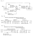
- Fig. 4A is a diagram schematically representing a temporal relationship between the image and sound when data receiver/demultiplexer 201 receives data 100 to be received.
- Fig. 4B is a diagram schematically representing a temporal relationship between the image and sound transferred from data synchronization/output unit 208.
- Data synchronization/output unit 208 encodes frame N of image data in the intra-mode to temporally move backward audio data m, m+1, m+2, m+3, m+4 corresponding to frame N of image data by a time consistent with the amount of codes that have increased beyond the amount of codes that were originally received.
- data synchronization/output unit 208 temporarily moves audio data m, m+1, m+2, m+3, m+4 corresponding to frame N of the image data after the conversion in the intra-mode backward to an extent that the audio data are synchronized with frame N of the converted image data.
- frame N upon transfer in Fig. 4B no audio data exists at the positions of audio data m through m+4 in frame N upon reception in Fig. 4A.
- Data synchronization/output unit 208 may insert mute data in this portion in which no audio data exists.
- the processing and function of respective data receiver/demultiplexer 201, image data converter 205, switch 206 and data synchronization/output unit 208 may be implemented by a program executed on a CPU (computer) which forms part of the moving image conversion apparatus.
- a program which defines the processing and function of respective data receiver/demultiplexer 201, image data converter 205, switch 206 and data synchronization/output unit 208 is recorded on a computer readable recording medium (for example, a memory), and the CPU which forms part of the moving image conversion apparatus reads the program from the recording medium for execution.
- a computer readable recording medium for example, a memory
- the moving image conversion apparatus of the foregoing embodiment may be combined with another communications apparatus to comprise a system, or may be applied to a server or the like to accumulate and deliver moving images, as a matter of course.
Landscapes
- Engineering & Computer Science (AREA)
- Multimedia (AREA)
- Signal Processing (AREA)
- General Engineering & Computer Science (AREA)
- Databases & Information Systems (AREA)
- Compression Or Coding Systems Of Tv Signals (AREA)
- Two-Way Televisions, Distribution Of Moving Picture Or The Like (AREA)
Applications Claiming Priority (2)
| Application Number | Priority Date | Filing Date | Title |
|---|---|---|---|
| JP2005297701 | 2005-10-12 | ||
| PCT/JP2006/317549 WO2007043256A1 (fr) | 2005-10-12 | 2006-09-05 | Méthode de conversion d’image animée, dispositif de conversion d’image animée, système de conversion d’image animée, dispositif serveur et programme |
Publications (2)
| Publication Number | Publication Date |
|---|---|
| EP1814334A1 true EP1814334A1 (fr) | 2007-08-01 |
| EP1814334A4 EP1814334A4 (fr) | 2010-04-28 |
Family
ID=37942514
Family Applications (1)
| Application Number | Title | Priority Date | Filing Date |
|---|---|---|---|
| EP06797454A Withdrawn EP1814334A4 (fr) | 2005-10-12 | 2006-09-05 | Méthode de conversion d'image animée, dispositif de conversion d'image animée, système de conversion d'image animée, dispositif serveur et programme |
Country Status (6)
| Country | Link |
|---|---|
| US (1) | US8229000B2 (fr) |
| EP (1) | EP1814334A4 (fr) |
| JP (1) | JP4853647B2 (fr) |
| KR (2) | KR20080104072A (fr) |
| CN (1) | CN100551068C (fr) |
| WO (1) | WO2007043256A1 (fr) |
Families Citing this family (8)
| Publication number | Priority date | Publication date | Assignee | Title |
|---|---|---|---|---|
| US8311095B2 (en) * | 2002-07-17 | 2012-11-13 | Onmobile Global Limited | Method and apparatus for transcoding between hybrid video codec bitstreams |
| KR20110138426A (ko) * | 2007-07-30 | 2011-12-27 | 닛본 덴끼 가부시끼가이샤 | 변환 장치, 배신 시스템, 및 배신 방법 |
| WO2009017105A1 (fr) * | 2007-07-30 | 2009-02-05 | Nec Corporation | Terminal de connexion, système de distribution, procédé de conversion et programme |
| JP2011155538A (ja) * | 2010-01-28 | 2011-08-11 | Toshiba Corp | メディア符号化装置及びメディア符号化方法 |
| CN102123279B (zh) * | 2010-12-28 | 2013-01-23 | 乐视网信息技术(北京)股份有限公司 | 一种分布式实时转码方法与系统 |
| KR101917174B1 (ko) * | 2012-02-24 | 2018-11-09 | 삼성전자주식회사 | 전자 장치 사이의 스트림 전송 방법 및 그 방법을 처리하는 전자 장치 |
| US10021432B2 (en) * | 2013-06-06 | 2018-07-10 | Nec Corporation | Time series data encoding apparatus, method, and program, and time series data re-encoding apparatus, method, and program |
| CN111220876B (zh) * | 2020-03-30 | 2022-12-06 | 厦门四信智慧电力科技有限公司 | 一种暂态录波数据压缩方法、装置、设备及存储介质 |
Family Cites Families (22)
| Publication number | Priority date | Publication date | Assignee | Title |
|---|---|---|---|---|
| JP3104805B2 (ja) * | 1991-10-02 | 2000-10-30 | 株式会社東芝 | テレビ電話 |
| JPH06276427A (ja) | 1993-03-23 | 1994-09-30 | Sony Corp | 動画像音声制御装置 |
| JPH07111620A (ja) * | 1993-10-14 | 1995-04-25 | Matsushita Electric Ind Co Ltd | 動画像圧縮データ切り換え装置 |
| JPH08102937A (ja) * | 1994-09-30 | 1996-04-16 | Canon Inc | 画像処理装置及び通信装置 |
| JP2822940B2 (ja) * | 1995-07-19 | 1998-11-11 | 日本電気株式会社 | 動画像音声データ編集装置 |
| WO1997009828A1 (fr) * | 1995-09-06 | 1997-03-13 | Philips Electronics N.V. | Procede et dispositif de codage d'une sequence d'images segmentees, signal code et support de stockage correspondants et procede et systeme de decodage dudit signal code |
| JPH1188847A (ja) | 1997-09-03 | 1999-03-30 | Hitachi Denshi Ltd | 映像・音声同期方式 |
| US6339760B1 (en) | 1998-04-28 | 2002-01-15 | Hitachi, Ltd. | Method and system for synchronization of decoded audio and video by adding dummy data to compressed audio data |
| JP2000078531A (ja) | 1998-04-28 | 2000-03-14 | Hitachi Ltd | オ―ディオデ―タ編集方法、編集システム |
| JP3860369B2 (ja) * | 1999-03-17 | 2006-12-20 | パイオニア株式会社 | ディジタル信号受信システムにおける判定帰還型等化器 |
| JP3834170B2 (ja) | 1999-10-22 | 2006-10-18 | 日本電気株式会社 | ビデオ符号処理システム |
| JP3871840B2 (ja) | 1999-12-24 | 2007-01-24 | 日本電気株式会社 | 圧縮動画像再符号化装置 |
| JP3976979B2 (ja) * | 2000-02-21 | 2007-09-19 | シャープ株式会社 | 画像編集装置 |
| JP2001251616A (ja) | 2000-03-02 | 2001-09-14 | Media Glue Corp | 多重化音響・動画圧縮符号化信号変換方法、装置および変換プログラムを記録した媒体 |
| US6748020B1 (en) * | 2000-10-25 | 2004-06-08 | General Instrument Corporation | Transcoder-multiplexer (transmux) software architecture |
| JP3840895B2 (ja) * | 2000-11-22 | 2006-11-01 | 日本電気株式会社 | 動画像符号化データ変換装置及びその方法 |
| JP3958531B2 (ja) | 2001-03-26 | 2007-08-15 | 池上通信機株式会社 | 同期制御装置 |
| JP2002300528A (ja) | 2001-03-30 | 2002-10-11 | Toshiba Corp | ビデオストリーム編集方法及び装置 |
| JP2002314940A (ja) | 2001-04-12 | 2002-10-25 | Hitachi Ltd | 画像蓄積再生装置および画像蓄積再生方法 |
| GB0300361D0 (en) | 2003-01-07 | 2003-02-05 | Koninkl Philips Electronics Nv | Audio-visual content transmission |
| US20040234140A1 (en) * | 2003-05-19 | 2004-11-25 | Shunichiro Nonaka | Apparatus and method for moving image conversion, apparatus and method for moving image transmission, and programs therefor |
| JP2005027163A (ja) * | 2003-07-04 | 2005-01-27 | Pioneer Electronic Corp | 音声データ処理装置、音声データ処理方法、そのプログラム、および、そのプログラムを記録した記録媒体 |
-
2006
- 2006-09-05 US US11/661,805 patent/US8229000B2/en not_active Expired - Fee Related
- 2006-09-05 EP EP06797454A patent/EP1814334A4/fr not_active Withdrawn
- 2006-09-05 CN CNB2006800010187A patent/CN100551068C/zh not_active Expired - Fee Related
- 2006-09-05 KR KR1020087025713A patent/KR20080104072A/ko not_active Withdrawn
- 2006-09-05 WO PCT/JP2006/317549 patent/WO2007043256A1/fr not_active Ceased
- 2006-09-05 JP JP2006552406A patent/JP4853647B2/ja not_active Expired - Fee Related
-
2007
- 2007-03-29 KR KR20077007151A patent/KR100917481B1/ko not_active Expired - Fee Related
Also Published As
| Publication number | Publication date |
|---|---|
| KR20080104072A (ko) | 2008-11-28 |
| JPWO2007043256A1 (ja) | 2009-04-16 |
| JP4853647B2 (ja) | 2012-01-11 |
| KR20070088547A (ko) | 2007-08-29 |
| US8229000B2 (en) | 2012-07-24 |
| WO2007043256A1 (fr) | 2007-04-19 |
| KR100917481B1 (ko) | 2009-09-16 |
| CN100551068C (zh) | 2009-10-14 |
| EP1814334A4 (fr) | 2010-04-28 |
| CN101040534A (zh) | 2007-09-19 |
| US20090232223A1 (en) | 2009-09-17 |
Similar Documents
| Publication | Publication Date | Title |
|---|---|---|
| EP1725042A1 (fr) | Procédé de fondu pour des signaux vidéo comprimés en MPEG | |
| US6792045B2 (en) | Image signal transcoder capable of bit stream transformation suppressing deterioration of picture quality | |
| JP4983917B2 (ja) | 動画像配信システム、変換装置および動画像配信方法 | |
| HUP0004848A2 (hu) | Berendezés és eljárás MPEG-2 adatfolyam SMPTE-259 kompatibilis adatfolyammá történő átalakítására | |
| KR100917481B1 (ko) | 동화상 변환 장치, 동화상 변환 시스템 및 서버 장치 | |
| JP2000059790A (ja) | 動画像符号列変換装置及びその方法 | |
| US20020039384A1 (en) | Digital signal coding method and apparatus, signal recording medium, and signal transmission method for recording a moving picture signal and an acoustic signal | |
| WO2008146892A1 (fr) | Appareil, procédé et programme de conversion d'images animées, | |
| AU766738B2 (en) | Data compression unit control for alignment of output signal | |
| JP3668556B2 (ja) | ディジタル信号符号化方法 | |
| US20050190833A1 (en) | Encoded data outputting apparatus and method | |
| EP0903041A2 (fr) | Ameliorations dans ou relatives a une modification du debit binaire d'un signal numerique | |
| JP4224778B2 (ja) | ストリーム変換装置および方法、符号化装置および方法、記録媒体、並びに、プログラム | |
| JP3487205B2 (ja) | 画像データ編集装置 | |
| CA2234010A1 (fr) | Ameliorations portant sur la modification d'un train binaire numerique | |
| JP3834170B2 (ja) | ビデオ符号処理システム | |
| JPH10191331A (ja) | 画像データの符号化方法及び装置 | |
| JP2007235989A (ja) | 画像処理装置および画像処理方法、プログラム、並びに、記録媒体 | |
| JPH1013826A (ja) | 画像符号化装置および画像符号化方法、画像復号化装置および画像復号化方法、画像送信装置、画像受信装置、並びに記録媒体 | |
| JP2005072995A (ja) | レート変換装置 | |
| JP4320509B2 (ja) | 映像再符号化装置および方法 | |
| JP2002218470A (ja) | 画像符号化データのレート変換方法、及び画像符号化レート変換装置 | |
| KR101054644B1 (ko) | 동작 추정 기반 영상 부호화/복호화 장치 및 방법 | |
| KR100998449B1 (ko) | Dmb 수신장치 및 그 버퍼제어 방법 | |
| JP2002077811A (ja) | データ処理方法及び装置、データ伝送システム、伝送媒体 |
Legal Events
| Date | Code | Title | Description |
|---|---|---|---|
| PUAI | Public reference made under article 153(3) epc to a published international application that has entered the european phase |
Free format text: ORIGINAL CODE: 0009012 |
|
| 17P | Request for examination filed |
Effective date: 20070321 |
|
| AK | Designated contracting states |
Kind code of ref document: A1 Designated state(s): AT BE BG CH CY CZ DE DK EE ES FI FR GB GR HU IE IS IT LI LT LU LV MC NL PL PT RO SE SI SK TR |
|
| AX | Request for extension of the european patent |
Extension state: AL BA HR MK YU |
|
| DAX | Request for extension of the european patent (deleted) | ||
| DAX | Request for extension of the european patent (deleted) | ||
| RBV | Designated contracting states (corrected) |
Designated state(s): DE FR GB |
|
| A4 | Supplementary search report drawn up and despatched |
Effective date: 20100331 |
|
| 17Q | First examination report despatched |
Effective date: 20110509 |
|
| STAA | Information on the status of an ep patent application or granted ep patent |
Free format text: STATUS: THE APPLICATION IS DEEMED TO BE WITHDRAWN |
|
| 18D | Application deemed to be withdrawn |
Effective date: 20120421 |