EP1815221B1 - Verfahren zur bestimmung des mittleren motorendrehmoments - Google Patents
Verfahren zur bestimmung des mittleren motorendrehmoments Download PDFInfo
- Publication number
- EP1815221B1 EP1815221B1 EP04822651A EP04822651A EP1815221B1 EP 1815221 B1 EP1815221 B1 EP 1815221B1 EP 04822651 A EP04822651 A EP 04822651A EP 04822651 A EP04822651 A EP 04822651A EP 1815221 B1 EP1815221 B1 EP 1815221B1
- Authority
- EP
- European Patent Office
- Prior art keywords
- engine
- value
- representative
- speed vector
- sampling period
- Prior art date
- Legal status (The legal status is an assumption and is not a legal conclusion. Google has not performed a legal analysis and makes no representation as to the accuracy of the status listed.)
- Expired - Lifetime
Links
- 238000000034 method Methods 0.000 title claims description 54
- 239000013598 vector Substances 0.000 claims abstract description 41
- 238000005070 sampling Methods 0.000 claims abstract description 26
- 238000002485 combustion reaction Methods 0.000 claims abstract description 10
- 238000004519 manufacturing process Methods 0.000 claims abstract description 6
- 238000004364 calculation method Methods 0.000 claims description 27
- 230000000694 effects Effects 0.000 claims description 5
- 230000009466 transformation Effects 0.000 claims description 5
- 230000006870 function Effects 0.000 claims description 4
- 238000004458 analytical method Methods 0.000 claims description 3
- 239000011159 matrix material Substances 0.000 claims description 3
- 238000005259 measurement Methods 0.000 description 8
- 230000008901 benefit Effects 0.000 description 5
- 238000010586 diagram Methods 0.000 description 3
- 238000012360 testing method Methods 0.000 description 3
- 230000006399 behavior Effects 0.000 description 2
- 238000011156 evaluation Methods 0.000 description 2
- 230000001788 irregular Effects 0.000 description 2
- 238000001514 detection method Methods 0.000 description 1
- 238000003745 diagnosis Methods 0.000 description 1
- 230000003292 diminished effect Effects 0.000 description 1
- 238000012067 mathematical method Methods 0.000 description 1
- 238000012986 modification Methods 0.000 description 1
- 230000004048 modification Effects 0.000 description 1
- 230000000737 periodic effect Effects 0.000 description 1
- 238000010587 phase diagram Methods 0.000 description 1
- 238000012545 processing Methods 0.000 description 1
- 230000008439 repair process Effects 0.000 description 1
Images


Classifications
-
- F—MECHANICAL ENGINEERING; LIGHTING; HEATING; WEAPONS; BLASTING
- F02—COMBUSTION ENGINES; HOT-GAS OR COMBUSTION-PRODUCT ENGINE PLANTS
- F02D—CONTROLLING COMBUSTION ENGINES
- F02D41/00—Electrical control of supply of combustible mixture or its constituents
- F02D41/0097—Electrical control of supply of combustible mixture or its constituents using means for generating speed signals
-
- F—MECHANICAL ENGINEERING; LIGHTING; HEATING; WEAPONS; BLASTING
- F02—COMBUSTION ENGINES; HOT-GAS OR COMBUSTION-PRODUCT ENGINE PLANTS
- F02D—CONTROLLING COMBUSTION ENGINES
- F02D41/00—Electrical control of supply of combustible mixture or its constituents
- F02D41/02—Circuit arrangements for generating control signals
- F02D41/14—Introducing closed-loop corrections
- F02D41/1497—With detection of the mechanical response of the engine
-
- G—PHYSICS
- G01—MEASURING; TESTING
- G01L—MEASURING FORCE, STRESS, TORQUE, WORK, MECHANICAL POWER, MECHANICAL EFFICIENCY, OR FLUID PRESSURE
- G01L3/00—Measuring torque, work, mechanical power, or mechanical efficiency, in general
- G01L3/24—Devices for determining the value of power, e.g. by measuring and simultaneously multiplying the values of torque and revolutions per unit of time, by multiplying the values of tractive or propulsive force and velocity
-
- F—MECHANICAL ENGINEERING; LIGHTING; HEATING; WEAPONS; BLASTING
- F02—COMBUSTION ENGINES; HOT-GAS OR COMBUSTION-PRODUCT ENGINE PLANTS
- F02D—CONTROLLING COMBUSTION ENGINES
- F02D41/00—Electrical control of supply of combustible mixture or its constituents
- F02D41/24—Electrical control of supply of combustible mixture or its constituents characterised by the use of digital means
- F02D41/26—Electrical control of supply of combustible mixture or its constituents characterised by the use of digital means using computer, e.g. microprocessor
- F02D41/28—Interface circuits
- F02D2041/286—Interface circuits comprising means for signal processing
- F02D2041/288—Interface circuits comprising means for signal processing for performing a transformation into the frequency domain, e.g. Fourier transformation
-
- F—MECHANICAL ENGINEERING; LIGHTING; HEATING; WEAPONS; BLASTING
- F02—COMBUSTION ENGINES; HOT-GAS OR COMBUSTION-PRODUCT ENGINE PLANTS
- F02D—CONTROLLING COMBUSTION ENGINES
- F02D2200/00—Input parameters for engine control
- F02D2200/02—Input parameters for engine control the parameters being related to the engine
- F02D2200/10—Parameters related to the engine output, e.g. engine torque or engine speed
- F02D2200/1002—Output torque
- F02D2200/1004—Estimation of the output torque
Definitions
- the present invention relates to a method for producing a value T being representative of the mean engine torque generated on a crankshaft of an internal combustion engine. It also relates to a device for producing such a value.
- a useful parameter is the engine torque generated on the crankshaft of an engine. Faults or irregularities in the function of the engine will result in diminished or irregular engine torque. In a more detailed diagnosis, once a faulty engine torque value has been detected, it could be further analysed so as to provide information regarding the likely source of error, such as an injector fault or other error source. Thus, it is desirable to provide a measure of the engine torque generated on a crankshaft of an engine in a vehicle.
- Previously, a number of methods have been proposed for determining the engine torque from selected measurements performed on the engine and using different mathematical methods.
- the object of the invention is to provide a measure of the mean engine torque generated on a crankshaft of an engine in a vehicle that is useful for engine diagnostic purposes. Another object of the invention is to provide a measure of the mean engine torque that may be used for diagnostics of an engine during normal operating conditions. Yet another object of the invention is to provide a measure of the mean engine torque that may give a sufficiently accurate measure whilst being limited to reasonable requirements for processor capacity, storage space etc.
- At least one of the above mentioned objects is achieved by a method for producing a value T being representative of the mean engine torque generated on a crankshaft of an internal combustion engine, comprising the steps of
- the method according to the invention provides a useful measure of the mean engine torque that has the advantage of being applicable to situations in which the vehicle is under load, i.e. during normal driving conditions. It has further the advantage that it is executable using a relatively low number of samples and using relatively few calculations, resulting in a fast calculation that may be made without need for additional processing power in the vehicle.
- the mean engine torque obtained using the method may be calculated at regular intervals during use of the vehicle and logged to provide a stored log being a chart over the vehicle's behaviour over time.
- the log may be studied and conclusions regarding the state of the engine and possible necessary repair or replacement work.
- a further advantage is that the mean engine torque measure obtained may be used to objectively evaluate the function of the engine.
- An ideal engine torque measure may be set for certain engine conditions and comparing the calculated engine torque with the ideal torque give an indication whether the engine fulfils the desired requirements or not.
- the internal combustion engine may be used in different applications, such as in vessels or vehicles.
- Vehicles include e.g. cars, heavy duty vehicles and tracked vehicles.
- the selected order x may be equal to the number of cylinders of the engine divided by two. This selection of the order has been found to reflect the effect of a four-stroke engine particularly well. For two-stroke engines, the selected order x may instead be equal to the number of cylinders.
- the sampling period corresponds to at least 10 rotations of the engine. Such a sampling period is long enough to ensure that the mean engine torque value includes the effect of all of the cylinders of the engine.
- the speed vector comprises values t being representative of instantaneous speeds of the engine being the passages of time between subsequent rotational indexing references arranged in connection with a flywheel or crankshaft of the engine.
- This embodiment provides an efficient and relatively reliable method for calculating values being representative of instantaneous engine speeds.
- the arrangement of the rotational indexing references is irregular at some locations.
- the method may comprise a compensation step when generating the speed vector, wherein effects of any irregularities in the arrangement of the rotational indexing references are compensated for.
- the value P x representing the power contribution for the frequency x*n is determined using a Fourier series analysis of the speed vector.
- the speed vector should preferably include at least 500 samples so as to give satisfactory resolution.
- the value P x may be determined by using a Fast Fourier Transform for the phase-amplitude transformation of the speed vector.
- the RMS value of the area under the peak at the frequency n*x in the phase-amplitude transformation is used as P x .
- the values t may advantageously be sampled with a sample interval with a duration of less than or equal to 10 microseconds, preferably less than or equal to 1 microsecond.
- the loading conditions during the sampling period may be selected so as to correspond to at least 50% load, preferably to at least 60% load. This is advantageous since the conditions correspond to normal conditions when a vehicle such as a truck is in use.
- the engine speeds during the sampling period may be selected to be at least 1000 rpm.
- higher engine speeds are used, and the engine speeds during the sampling period may be selected to be at least 1500 rpm.
- a value T produced according to the invention may be compared to reference value Tref being representative of the engine torque of a standard engine, to enable evaluation of the engine for which the value T was determined.
- a device for the production of a value T which is representative of the mean engine torque generated on a crankshaft of an internal combustion engine comprising a measuring device for measuring instantaneous speeds of the engine during a sampling period, calculation means for producing a speed vector of values being representative of the instantaneous speeds of the engine measured during said sampling period, calculation means to derive a mean engine speed n during said sampling time using the speed vector, calculation means to derive a value P x being representative of the power contribution for the frequency x*n from the speed vector, where x is a pre-selected order, and calculation means to derive the desired value T being representative of the mean engine torque on the crankshaft during said sampling period wherein T is derived from a mathematical expression including a polynomial having at least a term k* n* P x , wherein k is a polynomial constant, stored in a memory.
- a device according to the invention provides the same advantages and may be combined with especially advantageous features in accordance with the method according to the invention as described above.
- the calculation means may but must not all be comprised within one and the same calculation unit, such as a processor unit, a microprocessor, an embedded processor or other suitable calculation unit.
- the measuring device may comprise a sensor being arranged for sensing the passage of subsequent rotational indexing references arranged in connection to a flywheel or a crankshaft of the engine, said passages of time being the values t of the speed vector being representatives of instantaneous speeds of the engine.
- the measuring device comprises a calculation means for determining the speed between subsequent rotational indexing references.
- the calculation means may but need not be comprised in the same calculation unit as the previously mentioned calculation means of the device.
- Fig. 1 schematically illustrates an embodiment of a method and device according to the invention.
- the device comprises a sensor 5 for sensing the passage of subsequent indexing references 7 in the form of teeth provided in connection with a flywheel 6, which in turn is connected to a crankshaft of a combustion engine.
- the sensor 5 is adapted to measure the passage of indexing references at sample intervals having a duration of 1 microsecond, being equal to a frequency of 1 MHz.
- a frequency of 1 MHz or more results in particularly good results using the method and device of the invention.
- the indexing references 7 may be irregularly arranged, so that there are gaps between references at certain places. Therefore, the values of the speed vector V are corrected for the missing references by calculating the mean value for the missing references and the next reference, and replacing all of the relevant values with a mean value.
- the mean engine speed n during the sampling period is calculated from the speed vector V, and expressed in rotations/second.
- the speed vector V is used to produce a phase-amplitude representation, in which the value P x being representative of the power contribution at a selected frequency x*n is calculated.
- the method selected to determine the amplitude P x is a Fourier series of sines and cosines.
- other Fourier transform methods may also be useful. Nevertheless, the inventors have found that the sine and cosine method provides useful results without need of an excessive number of samples or calculation capacity.
- the sine and cosine method is a true phase-amplitude transformation only when all orders are included. In this case, all orders need not to be included, since it is sufficient to know the amplitude for the order x.
- the result is a linear equation system that may be solved in least square sense.
- [C] which includes the constants a0, a1, b1, a2, b2 ... ak, bk for a Fourier series.
- the necessary length of the measured speed vector V depends on the method used for calculating P x in the following method step, and of the accuracy wanted in the resulting torque value T. If P x is calculated using FFT analysis, a suitable vector length might be about 2000 samples. If P x instead is calculated using a sine and cosine transform, the length of the vector may be considerably shortened, to about 600 samples.
- the value T may be calculated regularly during use of the vehicle and stored in a log for possible evaluation at a regular service occasion or in particular if the driver turns to a garage suspecting that something is wrong with the vehicle.
- the value T may be used when assessing the function of newly produced vehicles for asserting that the engine torque reaches desired specifications. In both instances, the value T may be compared to a reference value Tref being determined by producing T for a number of reference vehicles.
- the appearance of T over time may be used to detect loss of power and to decide whether or not the engine fulfils predetermined requirements.
- the polynomial parameters k0, k1, k2 and k3 need to be determined for different situations. Engines and vehicles may probably be put together in groups, each group containing engines and vehicles having the same torque behaviour and using the same polynomial constants.
- the actual torque T may be measured using e.g. a dynamometer, and be compared to the mathematical expression of T at a number of measurement points being sufficient to set up an equation system from which the values of the constants may be derived.
- Torques were measured using the dynamometer and speed vectors were obtained using measurement of tooth pass time of the flywheel in 64 different load conditions with speeds from 1000 rpm up to 1800 rpm in step of 100 rpm, and loads from 65% to 100% in steps of 5% for each testing condition.
- Fig. 2 is a diagram showing the measured loads at different engine speeds.
- Tmeas are the torques measured using the dynamometer.
- the equation was set up for a number of measured torques, and the mean values of the polynomial constants calculated for each measured torque were used to determine the polynomial constants to use in the later torque calculation.
- the calculated versus the measured torque is plotted in Fig. 3 .
- the values calculated according to the polynomial above are good representatives of the measured values.
- a precision better than 3% has been found when using models according to the invention in the area of an engine speed of 1000 to 1800 rpm, and 65 to 100% load.
- the polynomial model gives good results for the unmodified engine and for the modified engines, which shows that the method is also useful for measuring torque when a fault of some kind arises in the engine.
Landscapes
- Engineering & Computer Science (AREA)
- Chemical & Material Sciences (AREA)
- Combustion & Propulsion (AREA)
- Mechanical Engineering (AREA)
- General Engineering & Computer Science (AREA)
- General Physics & Mathematics (AREA)
- Physics & Mathematics (AREA)
- Testing Of Engines (AREA)
- Combined Controls Of Internal Combustion Engines (AREA)
- Force Measurement Appropriate To Specific Purposes (AREA)
- Control Of Ac Motors In General (AREA)
- Control Of Motors That Do Not Use Commutators (AREA)
- Control Of Electric Motors In General (AREA)
Claims (21)
- Verfahren zur Erzeugung eines Wertes T, der für das mittlere Motordrehmoment repräsentativ ist, das an einer Kurbelwelle eines Verbrennungsmotors erzeugt wird, mit den Schritten- Erzeugung eines Drehzahlvektors, der Werte umfasst, die für die momentanen Drehzahlen des Motors während einer Abtastperiode repräsentativ sind,- Bestimmung einer mittleren Motordrehzahl n während der Abtastperiode aus dem Drehzahlvektor,- Bestimmung eines Wertes Px, der für die Kraftverteilung des Drehzahlvektors bei der Frequenz x*n repräsentativ ist, wobei x eine vorgewählte Ordnung ist,- und Erzeugung eines Wertes T, der für das mittlere Motordrehmoment an der Kurbelwelle während der Abtastperiode repräsentativ ist, wobei T aus einem mathematischen Ausdruck abgeleitet wird, der ein Polynom mit wenigstens einem Term k*n*Px umfasst, wobei k eine Polynomkonstante ist.
- Verfahren nach Anspruch 1, wobei T aus einem mathematischen Ausdruck abgeleitet wird, der das Polynom k0+k1 *Px+k2*n+k3*n*Px umfasst, wobei k0, k1, k2 und k3 Polynom konstanten sind.
- Verfahren nach Anspruch 1 oder 2, wobei T=k0 +k1 *Px+k2*n+k3*n*Px, wobei k0, k1, k2 und k3 Polynom konstanten sind.
- Verfahren nach einem der vorhergehenden Ansprüche, wobei die gewählte Ordnung x=(Anzahl der Zylinder des Motors)/2.
- Verfahren nach einem Ansprüche 1 bis 3, wobei der Motor ein Zweitaktmotor ist und die gewählte Ordnung x gleich der Anzahl der Zylinder ist.
- Verfahren nach einem der vorhergehenden Ansprüche, wobei die Abtastperiode wenigstens zehn Umdrehungen des Motors entspricht.
- Verfahren nach einem der vorhergehenden Ansprüche, wobei der Drehzahlvektor für die momentanen Drehzahlen des Verbrennungsmotors repräsentative Werte t umfasst, die die Zeitdurchläufe zwischen aufeinanderfolgenden Drehindexierungsreferenzen sind, die in Verbindung mit einer Schwungscheibe oder Kurbelwelle des Verbrennungsmotors angeordnet sind.
- Verfahren nach Anspruch 7, bei dem das Verfahren einen Kompensationsschritt umfasst, wenn der Drehzahlvektor erzeugt wird, wobei die Auswirkungen jeglicher Irregularitäten in der Anordnung der Drehindexierungsreferenzen kompensiert werden.
- Verfahren nach einem der vorhergehenden Ansprüche, bei dem der die Kraftverteilung für die Frequenz x*n repräsentierende Wert Px durch Verwendung einer Phasen-Amplitudentransformation des Drehzahlvektors bestimmt wird.
- Verfahren nach einem der vorhergehenden Ansprüche, bei dem der die Kraftverteilung für die Frequenz x*n repräsentierende Wert Px durch Verwendung einer Fourier-Reihenanalyse des Drehzahlvektors bestimmt wird.
- Verfahren nach Anspruch 9, bei dem die Amplitude Px durch Lösung eines Gleichungssystems bestimmt wird: [A] x [C] = [V], wobei V der f Abtastungen enthaltende Drehzahlvektor ist und A eine Matrix für k Ordnungen ist

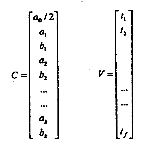
für die Koeffizienten ax und bx der vorhergewählten Ordnung x und Erhaltung der Amplitude
- Verfahren nach einem der vorhergehenden Ansprüche, wobei der Wert Px durch Verwendung einer Fast-Fourier-Transformation für die Phasen-Amplitudentransformation des Drehzahlvektors bestimmt wird.
- Verfahren nach Anspruch 12, bei dem Px bestimmt wird durch Plotten der Fast-Fourier-Transformation des Drehzahlvektors und Bestimmung des RMS-Werts des Bereichs unter einem Peak bei der Frequenz x*n.
- Verfahren nach einem der vorhergehenden Ansprüche, bei dem die Werte t mit einem Abtastintervall abgetastet werden, dessen Dauer geringer als oder gleich 10 Mikrosekunden ist, vorzugsweise weniger als oder gleich einer 1 Mikrosekunde.
- Verfahren nach einem der vorhergehenden Ansprüche, bei dem der Wert T für das mittlere Motordrehmoment bei den Lastbedingungen während der Abtastperiode repräsentativ ist, wobei die Bedingungen so gewählt werden, dass sie wenigstens einer 50%-Last entsprechen, vorzugsweise wenigstens einer 60%-Last.
- Verfahren nach einem der vorhergehenden Ansprüche, wobei der Wert T für das mittlere Motordrehmoment bei den Motordrehzahlen repräsentativ ist, die während der Abtastperiode verwendet werden, wobei die Motordrehzahlen so gewählt werden, dass sie wenigstens 1000 Umdrehungen pro Minute betragen.
- Verfahren zur Auswertung der Funktion eines Motors mit den Schritten- Erzeugung eines Werts T gemäß einem der Ansprüche 1 bis 16,- Vergleich des Werts T mit einem Referenzwert Tref, der für das Motordrehmoment eines Standardmotors repräsentativ ist.
- Vorrichtung zur Erzeugung eines Werts T, der für das mittlere Motordrehmoment repräsentativ ist, das an einer Kurbelwelle eines Verbrennungsmotors erzeugt wird, mit- einer Messvorrichtung zur Messung momentaner Drehzahlen des Motors während einer Abtastperiode,- einer Berechnungseinrichtung zur Erzeugung eines Drehzahlvektors von Werten, die für die momentanen Drehzahlen des Motors repräsentativ sind, die während der Abtastperiode gemessen wurden,- einer Berechnungseinrichtung zur Ableitung einer mittleren Motordrehzahl n während der Abtastzeit unter Verwendung des Drehzahlvektors,- einer Berechnungseinrichtung zur Ableitung eines Werts Px, der für die Kraftverteilung des Drehzahlvektors bei der Frequenz x*n repräsentativ ist, wobei x eine vorgewählte Ordnung ist, und- einer Berechnungseinrichtung zur Ableitung des gewünschten Werts T, der für das mittlere Motordrehmoment an der Kurbelwelle während der Abtastperiode repräsentativ ist, wobei T aus einem mathematischen Ausdruck abgeleitet wird, der ein Polynom mit wenigstens einem Term k*n*Px umfasst, wobei k eine in einem Speicher gespeicherte Polynomkonstante ist.
- Vorrichtung nach Anspruch 18, bei der die Messvorrichtung einen zur Erfassung des Durchlaufs von aufeinanderfolgenden, in Verbindung mit einem Schwungrad oder einer Kurbelwelle des Motors angeordneten Drehindexierungsreferenzen angeordneten Sensor aufweist, wobei die Zeitdurchläufe die Werte t des Drehzahlvektors sind, die für die momentanen Drehzahlen des Motors repräsentativ sind.
- Vorrichtung nach Anspruch 19, wobei die Messvorrichtung eine Berechnungseinrichtung zur Bestimmung der Drehzahl zwischen den aufeinanderfolgenden Drehindexierungsreferenzen ist.
- Vorrichtung nach einem der Ansprüche 18 bis 20 mit einer Berechnungseinrichtung zur Berechnung eines Kompensationsschritts, wenn der Drehzahlvektor erzeugt wird, wobei Auswirkungen irgendwelcher Irregularitäten in der Anordnung der Drehindexierungsreferenzen kompensiert werden.
Applications Claiming Priority (1)
| Application Number | Priority Date | Filing Date | Title |
|---|---|---|---|
| PCT/SE2004/001679 WO2006054928A1 (en) | 2004-11-17 | 2004-11-17 | Method for determination of mean engine torque |
Publications (2)
| Publication Number | Publication Date |
|---|---|
| EP1815221A1 EP1815221A1 (de) | 2007-08-08 |
| EP1815221B1 true EP1815221B1 (de) | 2010-10-06 |
Family
ID=36407409
Family Applications (1)
| Application Number | Title | Priority Date | Filing Date |
|---|---|---|---|
| EP04822651A Expired - Lifetime EP1815221B1 (de) | 2004-11-17 | 2004-11-17 | Verfahren zur bestimmung des mittleren motorendrehmoments |
Country Status (9)
| Country | Link |
|---|---|
| US (1) | US7742882B2 (de) |
| EP (1) | EP1815221B1 (de) |
| JP (1) | JP4934049B2 (de) |
| CN (1) | CN100491942C (de) |
| AT (1) | ATE483956T1 (de) |
| BR (1) | BRPI0419180A (de) |
| DE (1) | DE602004029512D1 (de) |
| ES (1) | ES2353768T3 (de) |
| WO (1) | WO2006054928A1 (de) |
Families Citing this family (8)
| Publication number | Priority date | Publication date | Assignee | Title |
|---|---|---|---|---|
| US7783448B2 (en) * | 2008-05-30 | 2010-08-24 | General Electric Company | Sensor processing method |
| US7570859B1 (en) | 2008-07-03 | 2009-08-04 | Microvision, Inc. | Optical substrate guided relay with input homogenizer |
| SE537656C2 (sv) * | 2013-06-10 | 2015-09-22 | Scania Cv Ab | Förfarande för estimering av ett moment genererat av en förbränningsmotor |
| KR101637646B1 (ko) | 2014-05-02 | 2016-07-07 | 현대자동차주식회사 | 표준 엔진 콜드 테스트 시스템 및 방법 |
| CN106066222B (zh) * | 2016-06-20 | 2019-03-05 | 常州易控汽车电子有限公司 | 一种发动机转矩估计的方法和系统 |
| EP3434177B1 (de) | 2017-07-27 | 2022-01-26 | Heraeus Deutschland GmbH & Co. KG | Selbstklebende elektrodenfläche |
| CA3076454A1 (en) * | 2017-10-04 | 2019-04-11 | The Board Of Trustees Of Western Michigan University | Torque sensor for engines |
| CN113818963B (zh) | 2021-09-23 | 2022-10-14 | 宁波吉利罗佑发动机零部件有限公司 | 发动机扭矩的预测方法、装置及计算机存储介质 |
Family Cites Families (15)
| Publication number | Priority date | Publication date | Assignee | Title |
|---|---|---|---|---|
| US4843870A (en) * | 1988-07-25 | 1989-07-04 | Purdue Research Foundation | Cylinder-by-cylinder engine pressure and pressure torque waveform determination utilizing crankshaft speed fluctuations |
| JPH0663761B2 (ja) * | 1988-12-12 | 1994-08-22 | 川崎製鉄株式会社 | ミスアライメントの検出方法及びその装置 |
| US5200899A (en) * | 1990-04-20 | 1993-04-06 | Regents Of The University Of Michigan | Method and system for detecting the misfire of an internal combustion engine utilizing angular velocity fluctuations |
| US5239473A (en) * | 1990-04-20 | 1993-08-24 | Regents Of The University Of Michigan | Method and system for detecting the misfire of an internal combustion engine utilizing angular velocity fluctuations |
| JP3226290B2 (ja) * | 1991-03-28 | 2001-11-05 | 株式会社日立製作所 | 内燃機関のトルク制御装置 |
| FR2681426B1 (fr) * | 1991-09-12 | 1993-11-26 | Renault Regie Nale Usines | Procede et dispositif de mesure du couple d'un moteur thermique a combustion interne tenant compte, notamment, de la recirculation des gaz d'echappement et des gaz brules residuels et de l'exces de comburant. |
| FR2681425B1 (fr) * | 1991-09-12 | 1993-11-26 | Renault Regie Nale Usines | Procede et dispositif de mesure du couple d'un moteur thermique a combustion interne. |
| US5771482A (en) * | 1995-12-15 | 1998-06-23 | The Ohio State University | Estimation of instantaneous indicated torque in multicylinder engines |
| US6029109A (en) * | 1996-04-15 | 2000-02-22 | Siemens Automotive S.A. | Method for calculating the torque of an internal combustion engine |
| US5753804A (en) * | 1996-08-01 | 1998-05-19 | Chrysler Corporation | Spatial frequency implemented digital filters for engine misfire detection |
| JP3478707B2 (ja) * | 1997-06-27 | 2003-12-15 | 株式会社日立製作所 | エンジンの燃焼状態診断装置およびその診断プログラムを記録した記録媒体 |
| US6223120B1 (en) * | 1998-11-19 | 2001-04-24 | Jeremy Williams | Cylinder torque estimation using crankshaft angular response measurements |
| JP2001352794A (ja) * | 2000-06-02 | 2001-12-21 | Toyota Motor Corp | フライホイール機構及びこれを備えた内燃機関 |
| WO2002071308A1 (en) * | 2001-03-05 | 2002-09-12 | The Ohio State University | Engine control using torque estimation |
| BRPI0520739A2 (pt) * | 2005-12-06 | 2009-05-26 | Volvo Lastvagnar Ab | método para determinação de pressão de injeção de combustìvel |
-
2004
- 2004-11-17 ES ES04822651T patent/ES2353768T3/es not_active Expired - Lifetime
- 2004-11-17 BR BRPI0419180-3A patent/BRPI0419180A/pt not_active Application Discontinuation
- 2004-11-17 JP JP2007541131A patent/JP4934049B2/ja not_active Expired - Fee Related
- 2004-11-17 WO PCT/SE2004/001679 patent/WO2006054928A1/en not_active Ceased
- 2004-11-17 CN CN200480044428.0A patent/CN100491942C/zh not_active Expired - Fee Related
- 2004-11-17 AT AT04822651T patent/ATE483956T1/de not_active IP Right Cessation
- 2004-11-17 DE DE602004029512T patent/DE602004029512D1/de not_active Expired - Lifetime
- 2004-11-17 US US11/577,890 patent/US7742882B2/en not_active Expired - Lifetime
- 2004-11-17 EP EP04822651A patent/EP1815221B1/de not_active Expired - Lifetime
Also Published As
| Publication number | Publication date |
|---|---|
| JP4934049B2 (ja) | 2012-05-16 |
| US7742882B2 (en) | 2010-06-22 |
| BRPI0419180A (pt) | 2007-12-18 |
| ES2353768T3 (es) | 2011-03-04 |
| DE602004029512D1 (de) | 2010-11-18 |
| EP1815221A1 (de) | 2007-08-08 |
| WO2006054928A1 (en) | 2006-05-26 |
| ATE483956T1 (de) | 2010-10-15 |
| JP2008520970A (ja) | 2008-06-19 |
| US20090132182A1 (en) | 2009-05-21 |
| CN101069077A (zh) | 2007-11-07 |
| CN100491942C (zh) | 2009-05-27 |
Similar Documents
| Publication | Publication Date | Title |
|---|---|---|
| US7623955B1 (en) | Method for estimation of indicated mean effective pressure for individual cylinders from crankshaft acceleration | |
| Williams | An overview of misfiring cylinder engine diagnostic techniques based on crankshaft angular velocity measurements | |
| Brown et al. | Determination of engine cylinder pressures from crankshaft speed fluctuations | |
| US20080190184A1 (en) | Fourier-based misfire detection strategy | |
| US6314802B1 (en) | Optimal engine speed compensation method used in misfire detection | |
| EP0637738A1 (de) | Verfahren und System zur Erfassung von Verbrennungsaussetzern bei Ottomotoren | |
| EP0635124B1 (de) | Verfahren und gerät zum detektieren von verbrennungsunregelmässigkeiten in einem motor hauptsächlich bei mittleren und höheren geschwindigkeiten | |
| US6230095B1 (en) | System and method for cylinder power imbalance prognostics and diagnostics | |
| EP1815221B1 (de) | Verfahren zur bestimmung des mittleren motorendrehmoments | |
| Hamedović et al. | IMEP-estimation and in-cylinder pressure reconstruction for multicylinder SI-engine by combined processing of engine speed and one cylinder pressure | |
| US7415351B2 (en) | Method and device for detecting an angular position signal for an internal-combustion engine | |
| Macián et al. | A comparison of different methods for fuel delivery unevenness detection in Diesel engines | |
| Ginoux et al. | Engine torque determination by crankangle measurements: state of the art, future prospects | |
| JPH04232828A (ja) | 内燃機関のシリンダ性能分析方法 | |
| JP4340284B2 (ja) | 燃焼異常指数の変化をフィルタリングすることにより内燃機関におけるミスファイヤを検出する方法 | |
| JP4804539B2 (ja) | 燃料供給圧の判定方法 | |
| WO2000022404A2 (en) | Process for diagnosing and locating misfiring cylinder through crankshaft torsional vibration measurement | |
| EP2078841B1 (de) | Überwachungseinheit und -verfahren | |
| Han | Tooth time-based engine misfire detection index for multicylinder engines of vehicles not affected by various deviations between cylinders | |
| JP4340285B2 (ja) | 燃焼異常指数を結合することにより内燃機関のミスファイヤを検出する方法 | |
| Williams | Individual cylinder IMEP estimation using crankshaft angular velocity measurements | |
| Ely et al. | Phase Detection Relevance in Engine Torque Determined by Instantaneous Engine Speed | |
| Han | Misfire Detection Index Distinguishing the Difference of the Engine Angular Acceleration Between Two Specified Teeth of the Sensor Wheel | |
| KR100490930B1 (ko) | 내연기관의토크계산방법 | |
| Ponti | Cylinder by Cylinder Torque Production non-Uniformity Evaluation |
Legal Events
| Date | Code | Title | Description |
|---|---|---|---|
| PUAI | Public reference made under article 153(3) epc to a published international application that has entered the european phase |
Free format text: ORIGINAL CODE: 0009012 |
|
| 17P | Request for examination filed |
Effective date: 20070618 |
|
| AK | Designated contracting states |
Kind code of ref document: A1 Designated state(s): AT BE BG CH CY CZ DE DK EE ES FI FR GB GR HU IE IS IT LI LU MC NL PL PT RO SE SI SK TR |
|
| DAX | Request for extension of the european patent (deleted) | ||
| 17Q | First examination report despatched |
Effective date: 20090414 |
|
| GRAP | Despatch of communication of intention to grant a patent |
Free format text: ORIGINAL CODE: EPIDOSNIGR1 |
|
| GRAS | Grant fee paid |
Free format text: ORIGINAL CODE: EPIDOSNIGR3 |
|
| GRAA | (expected) grant |
Free format text: ORIGINAL CODE: 0009210 |
|
| AK | Designated contracting states |
Kind code of ref document: B1 Designated state(s): AT BE BG CH CY CZ DE DK EE ES FI FR GB GR HU IE IS IT LI LU MC NL PL PT RO SE SI SK TR |
|
| REG | Reference to a national code |
Ref country code: GB Ref legal event code: FG4D |
|
| REG | Reference to a national code |
Ref country code: CH Ref legal event code: EP |
|
| REG | Reference to a national code |
Ref country code: IE Ref legal event code: FG4D |
|
| REF | Corresponds to: |
Ref document number: 602004029512 Country of ref document: DE Date of ref document: 20101118 Kind code of ref document: P |
|
| REG | Reference to a national code |
Ref country code: SE Ref legal event code: TRGR |
|
| REG | Reference to a national code |
Ref country code: NL Ref legal event code: T3 |
|
| PG25 | Lapsed in a contracting state [announced via postgrant information from national office to epo] |
Ref country code: SI Free format text: LAPSE BECAUSE OF FAILURE TO SUBMIT A TRANSLATION OF THE DESCRIPTION OR TO PAY THE FEE WITHIN THE PRESCRIBED TIME-LIMIT Effective date: 20101006 |
|
| REG | Reference to a national code |
Ref country code: ES Ref legal event code: FG2A Effective date: 20110222 |
|
| PG25 | Lapsed in a contracting state [announced via postgrant information from national office to epo] |
Ref country code: PT Free format text: LAPSE BECAUSE OF FAILURE TO SUBMIT A TRANSLATION OF THE DESCRIPTION OR TO PAY THE FEE WITHIN THE PRESCRIBED TIME-LIMIT Effective date: 20110207 Ref country code: BG Free format text: LAPSE BECAUSE OF FAILURE TO SUBMIT A TRANSLATION OF THE DESCRIPTION OR TO PAY THE FEE WITHIN THE PRESCRIBED TIME-LIMIT Effective date: 20110106 Ref country code: AT Free format text: LAPSE BECAUSE OF FAILURE TO SUBMIT A TRANSLATION OF THE DESCRIPTION OR TO PAY THE FEE WITHIN THE PRESCRIBED TIME-LIMIT Effective date: 20101006 Ref country code: IS Free format text: LAPSE BECAUSE OF FAILURE TO SUBMIT A TRANSLATION OF THE DESCRIPTION OR TO PAY THE FEE WITHIN THE PRESCRIBED TIME-LIMIT Effective date: 20110206 Ref country code: FI Free format text: LAPSE BECAUSE OF FAILURE TO SUBMIT A TRANSLATION OF THE DESCRIPTION OR TO PAY THE FEE WITHIN THE PRESCRIBED TIME-LIMIT Effective date: 20101006 |
|
| PG25 | Lapsed in a contracting state [announced via postgrant information from national office to epo] |
Ref country code: GR Free format text: LAPSE BECAUSE OF FAILURE TO SUBMIT A TRANSLATION OF THE DESCRIPTION OR TO PAY THE FEE WITHIN THE PRESCRIBED TIME-LIMIT Effective date: 20110107 Ref country code: BE Free format text: LAPSE BECAUSE OF FAILURE TO SUBMIT A TRANSLATION OF THE DESCRIPTION OR TO PAY THE FEE WITHIN THE PRESCRIBED TIME-LIMIT Effective date: 20101006 Ref country code: MC Free format text: LAPSE BECAUSE OF NON-PAYMENT OF DUE FEES Effective date: 20101130 |
|
| REG | Reference to a national code |
Ref country code: CH Ref legal event code: PL |
|
| PG25 | Lapsed in a contracting state [announced via postgrant information from national office to epo] |
Ref country code: CH Free format text: LAPSE BECAUSE OF NON-PAYMENT OF DUE FEES Effective date: 20101130 Ref country code: CZ Free format text: LAPSE BECAUSE OF FAILURE TO SUBMIT A TRANSLATION OF THE DESCRIPTION OR TO PAY THE FEE WITHIN THE PRESCRIBED TIME-LIMIT Effective date: 20101006 Ref country code: LI Free format text: LAPSE BECAUSE OF NON-PAYMENT OF DUE FEES Effective date: 20101130 Ref country code: EE Free format text: LAPSE BECAUSE OF FAILURE TO SUBMIT A TRANSLATION OF THE DESCRIPTION OR TO PAY THE FEE WITHIN THE PRESCRIBED TIME-LIMIT Effective date: 20101006 |
|
| PLBE | No opposition filed within time limit |
Free format text: ORIGINAL CODE: 0009261 |
|
| STAA | Information on the status of an ep patent application or granted ep patent |
Free format text: STATUS: NO OPPOSITION FILED WITHIN TIME LIMIT |
|
| PG25 | Lapsed in a contracting state [announced via postgrant information from national office to epo] |
Ref country code: DK Free format text: LAPSE BECAUSE OF FAILURE TO SUBMIT A TRANSLATION OF THE DESCRIPTION OR TO PAY THE FEE WITHIN THE PRESCRIBED TIME-LIMIT Effective date: 20101006 Ref country code: RO Free format text: LAPSE BECAUSE OF FAILURE TO SUBMIT A TRANSLATION OF THE DESCRIPTION OR TO PAY THE FEE WITHIN THE PRESCRIBED TIME-LIMIT Effective date: 20101006 Ref country code: SK Free format text: LAPSE BECAUSE OF FAILURE TO SUBMIT A TRANSLATION OF THE DESCRIPTION OR TO PAY THE FEE WITHIN THE PRESCRIBED TIME-LIMIT Effective date: 20101006 Ref country code: PL Free format text: LAPSE BECAUSE OF FAILURE TO SUBMIT A TRANSLATION OF THE DESCRIPTION OR TO PAY THE FEE WITHIN THE PRESCRIBED TIME-LIMIT Effective date: 20101006 |
|
| 26N | No opposition filed |
Effective date: 20110707 |
|
| PG25 | Lapsed in a contracting state [announced via postgrant information from national office to epo] |
Ref country code: IE Free format text: LAPSE BECAUSE OF NON-PAYMENT OF DUE FEES Effective date: 20101117 |
|
| REG | Reference to a national code |
Ref country code: DE Ref legal event code: R097 Ref document number: 602004029512 Country of ref document: DE Effective date: 20110707 |
|
| PG25 | Lapsed in a contracting state [announced via postgrant information from national office to epo] |
Ref country code: CY Free format text: LAPSE BECAUSE OF FAILURE TO SUBMIT A TRANSLATION OF THE DESCRIPTION OR TO PAY THE FEE WITHIN THE PRESCRIBED TIME-LIMIT Effective date: 20101006 |
|
| PG25 | Lapsed in a contracting state [announced via postgrant information from national office to epo] |
Ref country code: HU Free format text: LAPSE BECAUSE OF FAILURE TO SUBMIT A TRANSLATION OF THE DESCRIPTION OR TO PAY THE FEE WITHIN THE PRESCRIBED TIME-LIMIT Effective date: 20110407 Ref country code: LU Free format text: LAPSE BECAUSE OF NON-PAYMENT OF DUE FEES Effective date: 20101117 |
|
| PG25 | Lapsed in a contracting state [announced via postgrant information from national office to epo] |
Ref country code: TR Free format text: LAPSE BECAUSE OF FAILURE TO SUBMIT A TRANSLATION OF THE DESCRIPTION OR TO PAY THE FEE WITHIN THE PRESCRIBED TIME-LIMIT Effective date: 20101006 |
|
| REG | Reference to a national code |
Ref country code: FR Ref legal event code: PLFP Year of fee payment: 12 |
|
| REG | Reference to a national code |
Ref country code: FR Ref legal event code: PLFP Year of fee payment: 13 |
|
| PGFP | Annual fee paid to national office [announced via postgrant information from national office to epo] |
Ref country code: NL Payment date: 20161107 Year of fee payment: 13 Ref country code: GB Payment date: 20161107 Year of fee payment: 13 Ref country code: FR Payment date: 20161124 Year of fee payment: 13 |
|
| PGFP | Annual fee paid to national office [announced via postgrant information from national office to epo] |
Ref country code: ES Payment date: 20161114 Year of fee payment: 13 Ref country code: IT Payment date: 20161110 Year of fee payment: 13 |
|
| REG | Reference to a national code |
Ref country code: NL Ref legal event code: MM Effective date: 20171201 |
|
| GBPC | Gb: european patent ceased through non-payment of renewal fee |
Effective date: 20171117 |
|
| REG | Reference to a national code |
Ref country code: FR Ref legal event code: ST Effective date: 20180731 |
|
| PG25 | Lapsed in a contracting state [announced via postgrant information from national office to epo] |
Ref country code: NL Free format text: LAPSE BECAUSE OF NON-PAYMENT OF DUE FEES Effective date: 20171201 Ref country code: FR Free format text: LAPSE BECAUSE OF NON-PAYMENT OF DUE FEES Effective date: 20171130 Ref country code: IT Free format text: LAPSE BECAUSE OF NON-PAYMENT OF DUE FEES Effective date: 20171117 |
|
| PG25 | Lapsed in a contracting state [announced via postgrant information from national office to epo] |
Ref country code: GB Free format text: LAPSE BECAUSE OF NON-PAYMENT OF DUE FEES Effective date: 20171117 |
|
| PG25 | Lapsed in a contracting state [announced via postgrant information from national office to epo] |
Ref country code: ES Free format text: LAPSE BECAUSE OF NON-PAYMENT OF DUE FEES Effective date: 20171118 |
|
| PGFP | Annual fee paid to national office [announced via postgrant information from national office to epo] |
Ref country code: SE Payment date: 20221123 Year of fee payment: 19 Ref country code: DE Payment date: 20220527 Year of fee payment: 19 |
|
| REG | Reference to a national code |
Ref country code: DE Ref legal event code: R119 Ref document number: 602004029512 Country of ref document: DE |
|
| REG | Reference to a national code |
Ref country code: SE Ref legal event code: EUG |
|
| PG25 | Lapsed in a contracting state [announced via postgrant information from national office to epo] |
Ref country code: SE Free format text: LAPSE BECAUSE OF NON-PAYMENT OF DUE FEES Effective date: 20231118 |
|
| PG25 | Lapsed in a contracting state [announced via postgrant information from national office to epo] |
Ref country code: DE Free format text: LAPSE BECAUSE OF NON-PAYMENT OF DUE FEES Effective date: 20240601 |
|
| PG25 | Lapsed in a contracting state [announced via postgrant information from national office to epo] |
Ref country code: DE Free format text: LAPSE BECAUSE OF NON-PAYMENT OF DUE FEES Effective date: 20240601 |