EP1815982A2 - Guidage de feuilles dans un dispositif d'estampage - Google Patents
Guidage de feuilles dans un dispositif d'estampage Download PDFInfo
- Publication number
- EP1815982A2 EP1815982A2 EP06025499A EP06025499A EP1815982A2 EP 1815982 A2 EP1815982 A2 EP 1815982A2 EP 06025499 A EP06025499 A EP 06025499A EP 06025499 A EP06025499 A EP 06025499A EP 1815982 A2 EP1815982 A2 EP 1815982A2
- Authority
- EP
- European Patent Office
- Prior art keywords
- film
- web
- transfer
- sheet
- cylinder
- Prior art date
- Legal status (The legal status is an assumption and is not a legal conclusion. Google has not performed a legal analysis and makes no representation as to the accuracy of the status listed.)
- Granted
Links
Images

Classifications
-
- B—PERFORMING OPERATIONS; TRANSPORTING
- B41—PRINTING; LINING MACHINES; TYPEWRITERS; STAMPS
- B41F—PRINTING MACHINES OR PRESSES
- B41F19/00—Apparatus or machines for carrying out printing operations combined with other operations
- B41F19/02—Apparatus or machines for carrying out printing operations combined with other operations with embossing
- B41F19/06—Printing and embossing between a negative and a positive forme after inking and wiping the negative forme; Printing from an ink band treated with colour or "gold"
-
- B—PERFORMING OPERATIONS; TRANSPORTING
- B41—PRINTING; LINING MACHINES; TYPEWRITERS; STAMPS
- B41F—PRINTING MACHINES OR PRESSES
- B41F16/00—Transfer printing apparatus
Definitions
- the invention relates to a method and a device for transferring imaging or covering layers from a carrier foil to printed sheets according to the preamble of patent claim 1 and of patent claim 18, respectively.
- a printing sheet After a printing sheet is provided with a two-dimensional adhesive application or an adhesive pattern, it is passed through the coating unit, wherein by means of the pressure roller, the pressure sheet resting on the impression cylinder is brought into contact with the film material.
- the down-facing functional layer engages tightly with the adhesive-provided areas on the signature. Thereafter, the functional layer adheres only in the area provided with adhesive pattern or even full-surface adhesive areas on, wherein the carrier film, the functional layer is removed in the region of the adhesive pattern.
- the print sheet is laid out in the coated state.
- a disadvantage of the described procedures is that they are not flexible applicable, require extensive know-how on the complex processes and are difficult to handle. Above all, the previously known production methods are limited to the processing of substrates made of paper or cardboard. A coating of film substrates in the cold foil stamping process has not been previously known.
- the object of the invention is therefore to provide a method according to the preamble of claim 1 and a device according to the preamble of claim 18, by means of which a film coating of printed sheets of different quality films can be simple, safe, economical and accurate, with method and device easy should be manageable.
- a film coating module on a sheet-fed rotary printing press should offer an improvement in application quality in the case of a tangential film guide.
- a feed device is used to guide the transfer film, in which the transfer film is guided during feeding to the transfer nip by a modular control system.
- An associated device for feeding the transfer film advantageously has a guide device in the manner of a cassette module, by means of which the supply to the transfer nip and the removal from the transfer nip are made possible in a simple manner.
- the device can also be advantageously used in order to improve the use of the film by dividing the transfer film into one or more partial film webs of lesser width.
- a control of the transfer film can be carried out in such a way that, when passing through a cylinder channel receiving the gripper of the sheet, the film feed is stopped, the press roll then slidingly passing under the transfer film.
- the gripper back at the beginning of printing touches the application film and adversely affects surface finishing.
- the control of the deflection can be done via a mechanical cam mechanism or electro-pneumatic actuator which is controlled angle accurate on the real-time computer.
- the up or unwinding role have drives and brakes;
- the plate, rubber and printing cylinder has a channel and the printing cylinder are grippers for the transport of substrate.
- each sheet pass (rotation of the cylinder) leads to a web influence on the film web (web shortening in the channel has an effect on the web tension of the film).
- a (magnetic field) brake is on the film handling per web and on the film rewind a drive (friction shaft).
- the web tension is preset controlled on the operating panel of the module.
- the dancer is not used for single roles.
- the module continues to evolve in terms of channel clocking, with the web tension having to be reduced from a relatively high value to maintain channel continuity.
- dancer roller operation is also carried out with several individual rollers.
- the dancer virtually controls (controls) the common passage of the individual roller conveyors.
- the solution can be carried out pneumatically, wherein a dancer roller clamped on both sides can be controlled with an air cushion in the middle position via proportional valves. It is also a hydraulic, mechanical solution by means of springs and weights conceivable, etc.)
- the channel impact on the film web is to be cushioned, thus the effect channel / cylinder circumference is optimized to the web tension and it can be set a relatively constant web tension (web tension).
- the Folienholz- and -abwicklung can be performed with individual drives or drive-brake combination.
- the blanket cylinder or the press roll can also be a sleeve carrier. If necessary retracted in the channel area.
- the gripper may have a flat gripper back or be retracted largely in the channel (printing cylinder projection minimized).
- the applicator 1 may be a per se known offset printing unit with an inking unit 11, a plate cylinder 12 and a blanket cylinder 13.
- the blanket cylinder 13 cooperates with a counter-pressure cylinder 4.
- the coating unit 2 can also be formed by an offset printing unit.
- the transfer nip 6 in the coating unit 2 is formed by a press roll 3 and an impression cylinder 4.
- the press roller 3 may correspond to the blanket cylinder.
- the press roll 3 may also correspond to the forme cylinder of a paint module.
- a web guide 14 for transfer films is shown.
- the transfer film 5 is thereby switched on and executed by protective devices 15 of the coating unit 2.
- the press roll 3 (as blanket cylinder or forme cylinder or separate press roll) carries on its surface a compressible or damping, for example, also provided with a compressible intermediate layer element.
- a film transfer device integrated into the applicator 1 can be provided, whereby an integrated film application module is created.
- an additional press roll is assigned to a printing gap between a blanket or forme cylinder 13 and the impression cylinder 4 at an impression cylinder 4.
- a film web of a transfer film can be fed to a transfer nip formed as mentioned above and also discharged directly again.
- the cold foil stamping takes place in a single integrated foil application module.
- an applicator can be arranged in a compact design within the coating module.
- an adhesive application device is assigned to the impression cylinder 4 and arranged upstream of the transfer nip, which would be provided here between the blanket cylinder 13 and the impression cylinder 3.
- the transfer film would be guided here around the blanket cylinder 13 or approximately tangentially past it through the designated printing nip.
- Such an adhesive application device 1 ' may consist of a chamber doctor blade and an anilox roller for supplying the adhesive.
- the film supply roll 8 is assigned to the coating unit 2 on the side of the sheet feeder and has a rotary drive 7 for continuously controlled Feeding the transfer film to the coating unit 2.
- the film feed deflection or tension rollers for guiding the transfer film 5 may be provided in a substantially constant tension against the press roller 3.
- a film collecting roller 9 is provided for the used sheet material.
- a rotary drive 7 on the film collecting roller 9 is always advantageous. It can even be provided that the transfer film 5 is conveyed on the outlet side by means of the rotary drive 7 and held taut on the inlet side by means of a brake.
- the film feed of the transfer film 5 from the film supply roll 8 to the transfer nip 6 and the film collection roller 9 is gradually controlled, the transfer film 5 is then stopped, if no transfer of imaging or covering layers should take place.
- the associated device preferably includes a corresponding feed control for the transfer sheet 5, which ensures that at least the lying in the region of the press roller 3 and the impression cylinder 4 part of the film web is stationary as long as the cylinder channel passes.
- a further improvement of the film utilization of the type described results when the transfer film 5 is divided into one or more Operafolienbahnen lesser width.
- the utilization of the transfer film 5 can be improved even in zonally different lengths coating areas within an arc.
- the film application module dryer 16 may be provided, by means of which the adhesive application or the entire film coating can be dried.
- the film application module may include a monitoring device 17 for scanning the sheet surface with evaluation of image contents of the coating and detection of defects in the film coating.
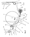
- a device for guiding the film on the press roll 3 is provided according to FIG. 2, which is guided substantially tangentially to the press roll 3 through the transfer nip 6 with the impression cylinder 4 of the coating unit 2.
- a film guiding device 20 and optionally a film feeding device guide the film web 5 in the transport direction T through the coating unit 3.
- a film guide 14 which is aligned approximately tangentially between the press roll 3 and the impression cylinder 4 and forms a wrap of the press roll 3 by less than 90 degrees.
- the film guide 14 for a film web 5 or partial film webs 19 includes on the feed side to the transfer nip 6, starting from an inlet opening 16 on a printing unit protection 15 some guide rollers 22nd
- the film guide 14 may be arranged as shown in FIG. 2 connected to a so-called Druckzylinderblasvorraum 36. This has nozzles for the formation of blown jets S in order to guide substrates on the impression cylinder 4 in front of the transfer nip 6, which can also keep the transfer film 5 taut and smooth.
- Another part of the film guide 14 includes on the discharge side of the transfer nip 6, starting at an exit opening 17 on a printing unit protection 15 further guide rollers 32, 34th
- the film guide 14 is arranged here in conjunction with an inlet protection 33. This serves to secure the transfer gap 6 against unintentional interventions.
- the film web 5 can be guided around the inlet protection 33 or through openings in its contour.
- the guide rollers 32, 34 may be arranged in conjunction with the printing unit protection 15, so that they take along the film web 5 during its displacement.
- the guide roller 34 may be arranged to be adjustable, so that the wrap angle Z of the film web 5 on the press roller 3 is adjustable.
- the transfer film 5 can come into contact with the counter-pressure cylinder 4 during a channel pass in the transfer nip 6 with grippers G.
- the grippers G hold a sheet B at its front edge on the impression cylinder 3 for secure transport through the transfer nip 6 fixed. With their so-called gripper back in the region of the pinching of the edge of the printing sheet B, they project to a slight extent over the circumference of the counter-pressure cylinder 4. Coordination to a channel also present on the press roll 3 is selected such that its associated edge comes into contact with the impression cylinder 4 only after the contour of the gripper G has arrived.
- the grippers G can press into the film web 5 which is not supported there.
- the gripper G are formed with a projecting in the smallest possible extent over the circumference of the impression cylinder 4 contour.
- systems of grippers G can be used, the total are permanently or cyclically adjustable radially to the impression cylinder 4, so that the height of the gripper G can be minimized over the cylinder contour.
- the film guide can be further supported by the fact that the cylinder channel of the press roll 3 is provided with a cover for largely cylindrical complement of the surface of the press roll. As a result, the film web 5 is indeed brought closer to the impression cylinder 4 in the area of the gripper G, but the film guide is overall more continuous and quiet.
- the guide of the transfer film 5 can be influenced by a further guide roller 38 (see FIG. 1), which is arranged in the region after the film removal from the film supply roll 8.
- This guide roller 38 in their Axle position is adjustable relative to the position of the axis of the film supply roll 8, unevenness or irregularities of the film flow from the film supply roll 8 before feeding the film web 5 to the film guide 14 can be compensated.
- the film collecting roller 9 may be associated with a pressure roller 31 (see FIG. 1) with adjustable pressure force and bias as a friction and leadership role.
- a defined tension (film tension) can be maintained on the film collecting roller 9, so that the film web 5 extends only to a very limited extent laterally and disturbances for this reason are avoided.
- a film guide can be provided at the edges of the film web 5 via flanges or suitable guide surfaces, so that no lateral film run can take place from the winding core and thus a film wound roll 9 is wound up.
- a guide roller 34 is used, by means of which a deflection angle X between the tangent plane on the press roller 3 in the transfer nip 6 and the plane in the deflection direction of the transfer film 5 can be changed.
- the control of the change of the deflection angle X of the transfer film 5 by means of the guide roller 34 can be effected via a mechanical cam mechanism, an electric drive or an electro-pneumatic actuator, which is designed to be actuated angularly via a real-time computer.
- the idler 34 is on a mounted linearly displaceable or pivotable holder and substantially in the direction of the double arrow of FIG. 2 displaced.
- web tension variations occurring according to the invention are compensated during the passage of the cylinder passages 3.1 or 4.1 of impression cylinder 4 and press roll 3. This is done by extending the path of the film web when the cylinder channels 3.1 and 4.1 in the transfer gap 6 face each other or by shortening the path of the film web after passing through the cylinder channels 3.1 and 4.1.
- signals of e.g. in the axis of rotation of the rotary drive 7 mounted sensor are guided to the take-up reel 9 and compensated by speed adjustment.
- a clocked film deflection of this type can also be provided on the film inlet side.
- one of the guide rollers 23 or 24 corresponding to the guide roller 34 is arranged to be movable and controllable.
- a deflection angle Y of the film web between the tangent plane on the press roller 3 in the transfer nip 6 and the plane in the deflection direction of the transfer film 5 when entering the transfer nip 6 is changed.
- the deflection angle Y in connection with the passage of the cylinder channels 3.1 and 4.1 are designed to be cyclically variable.
- the adjustment of the dancer rollers 18 may be carried out pneumatically, wherein a dancer roller 18 clamped on both sides can be controlled with an air cushion in the middle position via proportional valves. It is also a hydraulic, mechanical solution by means of springs and weights conceivable, etc.)
- a cyclic force acting as a channel impact on the film web which disturbs its guiding behavior and the entry into the transfer nip, can thus be cushioned.
- the effect of the known changes of the web path of the film web in the interaction of cylinder channel and cylinder circumference on the web tension can thus be compensated and a be set relatively constant web tension (web tension).
- the partial webs can be passed over in each case a separate dancer roller 18 to produce a constant web tension.
- the Folienauf- and -abwicklung can be performed with individual drives or drive-brake combination.
- an additional guide can be introduced advantageously. This limits the shortening path of the film in the channel passage.
- a channel cover may be provided in the blanket cylinder or the press roll 3, which complements the surface of the blanket cylinder or the press roller 3 substantially continuously.
- the blanket cylinder or the press roll may also be a sleeve carrier, which may be retracted in the channel region.
- the grippers G of the impression cylinder 4 may have a flat gripper back or may be largely retracted in the channel, so that the printing cylinder projection is minimized.
- the web tension of the film web can be controlled according to a desired-actual-value comparison to an appropriate for the film web web tension.
- the plate cylinder can be parked by the blanket cylinder or the press roll 3 and driven without contact.
- the plate cylinder and the inking unit are preferably shut down in the application module.
- a direct drive of the plate cylinder is advantageous with its own drive motor.
- the inking unit can be disengaged from the drive of the printing unit that forms the application module and thus shut down.
- the demolition angle on the outlet side by changing the distance of the guide roller 34 can be changed independently of a clock cycle.
- the change in the inlet angle can be done by a change in position of the inlet deflection by means of the guide roller 24.
- a continuous adjustment between maximum positions for Abrisswinkelver be provided on the outlet and the inlet side of the film web.
Landscapes
- Engineering & Computer Science (AREA)
- Mechanical Engineering (AREA)
- Rotary Presses (AREA)
- Non-Metallic Protective Coatings For Printed Circuits (AREA)
Applications Claiming Priority (2)
| Application Number | Priority Date | Filing Date | Title |
|---|---|---|---|
| DE102005062499 | 2005-12-27 | ||
| DE102006056896A DE102006056896A1 (de) | 2005-12-27 | 2006-12-02 | Folienführung in einer Prägeeinrichtung |
Publications (4)
| Publication Number | Publication Date |
|---|---|
| EP1815982A2 true EP1815982A2 (fr) | 2007-08-08 |
| EP1815982A3 EP1815982A3 (fr) | 2007-12-26 |
| EP1815982B1 EP1815982B1 (fr) | 2013-02-13 |
| EP1815982B2 EP1815982B2 (fr) | 2017-01-18 |
Family
ID=38109027
Family Applications (1)
| Application Number | Title | Priority Date | Filing Date |
|---|---|---|---|
| EP06025499.2A Not-in-force EP1815982B2 (fr) | 2005-12-27 | 2006-12-09 | Guidage de feuilles dans un dispositif d'estampage |
Country Status (2)
| Country | Link |
|---|---|
| EP (1) | EP1815982B2 (fr) |
| DE (1) | DE102006056896A1 (fr) |
Cited By (3)
| Publication number | Priority date | Publication date | Assignee | Title |
|---|---|---|---|---|
| WO2009144106A1 (fr) * | 2008-05-28 | 2009-12-03 | Manroland Ag | Guidage de feuille dans un dispositif de gaufrage |
| EP2161130A2 (fr) | 2008-09-04 | 2010-03-10 | LEONHARD KURZ Stiftung & Co. KG | Dispositif de transfert |
| US10710360B2 (en) * | 2016-05-30 | 2020-07-14 | Vinnovation Holding B.V. | Device that is configured to handle foil for use in a printing process |
Families Citing this family (4)
| Publication number | Priority date | Publication date | Assignee | Title |
|---|---|---|---|---|
| DE102007034246B4 (de) | 2007-07-23 | 2010-10-28 | OCé PRINTING SYSTEMS GMBH | Einrichtung mit einer Vorzentriervorrichtung und einer Puffervorrichtung für die Zufuhr einer Bedruckstoffbahn zu einer Druckeinrichtung |
| DE102007063763B3 (de) * | 2007-07-23 | 2016-02-04 | Océ Printing Systems GmbH & Co. KG | Puffervorrichtungen für die Zufuhr einer Bedruckstoffbahn zu einer Druckeinrichtung |
| DE102008059309B4 (de) | 2007-12-28 | 2019-03-28 | manroland sheetfed GmbH | Beschichtungseinrichtung mit separatem Zylinderantrieb |
| DE102008055142A1 (de) * | 2008-12-23 | 2010-07-01 | Manroland Ag | Betrieb eines Kaltfolienaggregates mit einem Druckwerk |
Citations (2)
| Publication number | Priority date | Publication date | Assignee | Title |
|---|---|---|---|---|
| DE4025712C1 (fr) | 1990-08-14 | 1991-09-12 | Walter Steinhausen Ch Mathis | |
| EP0569520B1 (fr) | 1991-01-29 | 1996-01-17 | CROS, Jean-Pierre | Materiau pour impression et installation d'impression au moyen de ce materiau |
Family Cites Families (8)
| Publication number | Priority date | Publication date | Assignee | Title |
|---|---|---|---|---|
| GB9409629D0 (en) * | 1994-05-13 | 1994-07-06 | Prittie Allan R | Method and apparatus for foil transfer |
| DE9420707U1 (de) † | 1994-12-24 | 1995-02-16 | Steuer, Armin, 71111 Waldenbuch | Präge-Rotationsmaschine |
| GB2368313B (en) † | 2000-10-28 | 2004-03-03 | Blockfoil Group Ltd | Cold foil stamping |
| DE102005008940C5 (de) † | 2004-04-13 | 2017-01-12 | manroland sheetfed GmbH | Vorrichtung zum Prägefoliendruck |
| DE102005011696A1 (de) * | 2004-04-13 | 2005-11-24 | Man Roland Druckmaschinen Ag | Prägeeinrichtung mit Folienbehandlung in einer Bogendruckmaschine |
| DE102005011568A1 (de) * | 2004-04-13 | 2005-11-17 | Man Roland Druckmaschinen Ag | Produktionsverfahren für eine Prägeeinrichtung in einer Bogendruckmaschine |
| CN101111380B (zh) * | 2005-02-04 | 2012-03-07 | 曼罗兰公司 | 用于压印装置的薄膜导向装置 |
| DE102005037496A1 (de) * | 2005-08-09 | 2007-02-15 | Man Roland Druckmaschinen Ag | Überwachungseinrichtung einer Folienführung |
-
2006
- 2006-12-02 DE DE102006056896A patent/DE102006056896A1/de not_active Withdrawn
- 2006-12-09 EP EP06025499.2A patent/EP1815982B2/fr not_active Not-in-force
Patent Citations (2)
| Publication number | Priority date | Publication date | Assignee | Title |
|---|---|---|---|---|
| DE4025712C1 (fr) | 1990-08-14 | 1991-09-12 | Walter Steinhausen Ch Mathis | |
| EP0569520B1 (fr) | 1991-01-29 | 1996-01-17 | CROS, Jean-Pierre | Materiau pour impression et installation d'impression au moyen de ce materiau |
Cited By (5)
| Publication number | Priority date | Publication date | Assignee | Title |
|---|---|---|---|---|
| WO2009144106A1 (fr) * | 2008-05-28 | 2009-12-03 | Manroland Ag | Guidage de feuille dans un dispositif de gaufrage |
| EP2161130A2 (fr) | 2008-09-04 | 2010-03-10 | LEONHARD KURZ Stiftung & Co. KG | Dispositif de transfert |
| DE102008045682A1 (de) | 2008-09-04 | 2010-03-11 | Leonhard Kurz Stiftung & Co. Kg | Transfervorrichtung |
| EP2161130A3 (fr) * | 2008-09-04 | 2011-04-13 | Leonhard Kurz Stiftung & Co. KG | Dispositif de transfert |
| US10710360B2 (en) * | 2016-05-30 | 2020-07-14 | Vinnovation Holding B.V. | Device that is configured to handle foil for use in a printing process |
Also Published As
| Publication number | Publication date |
|---|---|
| EP1815982A3 (fr) | 2007-12-26 |
| EP1815982B2 (fr) | 2017-01-18 |
| DE102006056896A1 (de) | 2007-06-28 |
| EP1815982B1 (fr) | 2013-02-13 |
Similar Documents
| Publication | Publication Date | Title |
|---|---|---|
| EP1737664B1 (fr) | Dispositif de gaufrage | |
| EP2296891B1 (fr) | Dispositif de gaufrage de feuilles à froid | |
| EP2288505B1 (fr) | Procédé et dispositif pour l application d une matière pelliculaire à froid sur une matière en feuille dans une machine d usinage | |
| EP1846242B1 (fr) | Guidage de films pour un dispositif d'estampage | |
| EP2382095B1 (fr) | Fonctionnement d'une unité pour film à froid pourvue d'un groupe d'impression | |
| EP1803563B1 (fr) | Procédé de gaufrage à froid | |
| EP1815982B1 (fr) | Guidage de film dans un dispositif d'estampage | |
| EP3013586B1 (fr) | Gaufrage de feuilles à froid en rapport avec le format | |
| DE102006004094B4 (de) | Folienführung für eine Prägeeinrichtung | |
| WO2011141359A1 (fr) | Réserve de feuilles dans un dispositif de gaufrage de feuilles à froid | |
| EP1676702B1 (fr) | Transfert de feuille et gaufrage à froid | |
| DE102008000743B4 (de) | Folienführung in einem Kaltfolienaggregat | |
| WO2008080487A1 (fr) | Guidage de film dans une unité de transfert de film | |
| DE102005005491B4 (de) | Folienzuführung für Kaltfolienprägung | |
| DE102018215355A1 (de) | Maschinenanordnung zum sequentiellen Bearbeiten bogenförmiger Substrate | |
| EP1985448A2 (fr) | Guidage de feuille dans un agrégat de feuilles à froid | |
| WO2009144106A1 (fr) | Guidage de feuille dans un dispositif de gaufrage | |
| EP2571694B1 (fr) | Dispositif de gaufrage à froid en fonction du format | |
| EP1674260B1 (fr) | Procédé de transfert | |
| WO2025163052A1 (fr) | Dispositif dans une presse d'impression offset de feuilles pour une impression sur des feuilles imprimées | |
| DE102005060588A1 (de) | Folienzuführung für Kaltfolienprägung | |
| EP1700693A2 (fr) | Procédé de gaufrage et dispositif associé pour matériaux d'imprimage aves surface structurée dans une machine à imprimer en feuilles | |
| DE102007014564A1 (de) | Folientransfer mit integrierter Trocknung |
Legal Events
| Date | Code | Title | Description |
|---|---|---|---|
| PUAI | Public reference made under article 153(3) epc to a published international application that has entered the european phase |
Free format text: ORIGINAL CODE: 0009012 |
|
| AK | Designated contracting states |
Kind code of ref document: A2 Designated state(s): AT BE BG CH CY CZ DE DK EE ES FI FR GB GR HU IE IS IT LI LT LU LV MC NL PL PT RO SE SI SK TR |
|
| AX | Request for extension of the european patent |
Extension state: AL BA HR MK YU |
|
| PUAL | Search report despatched |
Free format text: ORIGINAL CODE: 0009013 |
|
| AK | Designated contracting states |
Kind code of ref document: A3 Designated state(s): AT BE BG CH CY CZ DE DK EE ES FI FR GB GR HU IE IS IT LI LT LU LV MC NL PL PT RO SE SI SK TR |
|
| AX | Request for extension of the european patent |
Extension state: AL BA HR MK YU |
|
| RAP1 | Party data changed (applicant data changed or rights of an application transferred) |
Owner name: MANROLAND AG |
|
| 17P | Request for examination filed |
Effective date: 20080626 |
|
| AKX | Designation fees paid |
Designated state(s): AT BE BG CH CY CZ DE DK EE ES FI FR GB GR HU IE IS IT LI LT LU LV MC NL PL PT RO SE SI SK TR |
|
| 17Q | First examination report despatched |
Effective date: 20090401 |
|
| GRAP | Despatch of communication of intention to grant a patent |
Free format text: ORIGINAL CODE: EPIDOSNIGR1 |
|
| RTI1 | Title (correction) |
Free format text: FOIL GUIDE IN AN EMBOSSING DEVICE |
|
| 19U | Interruption of proceedings before grant |
Effective date: 20120201 |
|
| 19W | Proceedings resumed before grant after interruption of proceedings |
Effective date: 20121001 |
|
| GRAS | Grant fee paid |
Free format text: ORIGINAL CODE: EPIDOSNIGR3 |
|
| RAP1 | Party data changed (applicant data changed or rights of an application transferred) |
Owner name: MANROLAND SHEETFED GMBH |
|
| GRAA | (expected) grant |
Free format text: ORIGINAL CODE: 0009210 |
|
| AK | Designated contracting states |
Kind code of ref document: B1 Designated state(s): AT BE BG CH CY CZ DE DK EE ES FI FR GB GR HU IE IS IT LI LT LU LV MC NL PL PT RO SE SI SK TR |
|
| REG | Reference to a national code |
Ref country code: GB Ref legal event code: FG4D Free format text: NOT ENGLISH |
|
| REG | Reference to a national code |
Ref country code: AT Ref legal event code: REF Ref document number: 596244 Country of ref document: AT Kind code of ref document: T Effective date: 20130215 |
|
| REG | Reference to a national code |
Ref country code: IE Ref legal event code: FG4D Free format text: LANGUAGE OF EP DOCUMENT: GERMAN |
|
| REG | Reference to a national code |
Ref country code: DE Ref legal event code: R096 Ref document number: 502006012486 Country of ref document: DE Effective date: 20130411 |
|
| PLBI | Opposition filed |
Free format text: ORIGINAL CODE: 0009260 |
|
| REG | Reference to a national code |
Ref country code: NL Ref legal event code: VDEP Effective date: 20130213 |
|
| REG | Reference to a national code |
Ref country code: LT Ref legal event code: MG4D |
|
| PG25 | Lapsed in a contracting state [announced via postgrant information from national office to epo] |
Ref country code: ES Free format text: LAPSE BECAUSE OF FAILURE TO SUBMIT A TRANSLATION OF THE DESCRIPTION OR TO PAY THE FEE WITHIN THE PRESCRIBED TIME-LIMIT Effective date: 20130524 Ref country code: BG Free format text: LAPSE BECAUSE OF FAILURE TO SUBMIT A TRANSLATION OF THE DESCRIPTION OR TO PAY THE FEE WITHIN THE PRESCRIBED TIME-LIMIT Effective date: 20130513 Ref country code: SE Free format text: LAPSE BECAUSE OF FAILURE TO SUBMIT A TRANSLATION OF THE DESCRIPTION OR TO PAY THE FEE WITHIN THE PRESCRIBED TIME-LIMIT Effective date: 20130213 Ref country code: IS Free format text: LAPSE BECAUSE OF FAILURE TO SUBMIT A TRANSLATION OF THE DESCRIPTION OR TO PAY THE FEE WITHIN THE PRESCRIBED TIME-LIMIT Effective date: 20130613 Ref country code: LT Free format text: LAPSE BECAUSE OF FAILURE TO SUBMIT A TRANSLATION OF THE DESCRIPTION OR TO PAY THE FEE WITHIN THE PRESCRIBED TIME-LIMIT Effective date: 20130213 |
|
| 26 | Opposition filed |
Opponent name: HEIDELBERGER DRUCKMASCHINEN AG Effective date: 20130704 |
|
| PG25 | Lapsed in a contracting state [announced via postgrant information from national office to epo] |
Ref country code: PT Free format text: LAPSE BECAUSE OF FAILURE TO SUBMIT A TRANSLATION OF THE DESCRIPTION OR TO PAY THE FEE WITHIN THE PRESCRIBED TIME-LIMIT Effective date: 20130613 Ref country code: GR Free format text: LAPSE BECAUSE OF FAILURE TO SUBMIT A TRANSLATION OF THE DESCRIPTION OR TO PAY THE FEE WITHIN THE PRESCRIBED TIME-LIMIT Effective date: 20130514 Ref country code: FI Free format text: LAPSE BECAUSE OF FAILURE TO SUBMIT A TRANSLATION OF THE DESCRIPTION OR TO PAY THE FEE WITHIN THE PRESCRIBED TIME-LIMIT Effective date: 20130213 Ref country code: SI Free format text: LAPSE BECAUSE OF FAILURE TO SUBMIT A TRANSLATION OF THE DESCRIPTION OR TO PAY THE FEE WITHIN THE PRESCRIBED TIME-LIMIT Effective date: 20130213 Ref country code: PL Free format text: LAPSE BECAUSE OF FAILURE TO SUBMIT A TRANSLATION OF THE DESCRIPTION OR TO PAY THE FEE WITHIN THE PRESCRIBED TIME-LIMIT Effective date: 20130213 Ref country code: LV Free format text: LAPSE BECAUSE OF FAILURE TO SUBMIT A TRANSLATION OF THE DESCRIPTION OR TO PAY THE FEE WITHIN THE PRESCRIBED TIME-LIMIT Effective date: 20130213 |
|
| REG | Reference to a national code |
Ref country code: DE Ref legal event code: R026 Ref document number: 502006012486 Country of ref document: DE Effective date: 20130704 |
|
| PG25 | Lapsed in a contracting state [announced via postgrant information from national office to epo] |
Ref country code: CZ Free format text: LAPSE BECAUSE OF FAILURE TO SUBMIT A TRANSLATION OF THE DESCRIPTION OR TO PAY THE FEE WITHIN THE PRESCRIBED TIME-LIMIT Effective date: 20130213 Ref country code: RO Free format text: LAPSE BECAUSE OF FAILURE TO SUBMIT A TRANSLATION OF THE DESCRIPTION OR TO PAY THE FEE WITHIN THE PRESCRIBED TIME-LIMIT Effective date: 20130213 Ref country code: EE Free format text: LAPSE BECAUSE OF FAILURE TO SUBMIT A TRANSLATION OF THE DESCRIPTION OR TO PAY THE FEE WITHIN THE PRESCRIBED TIME-LIMIT Effective date: 20130213 Ref country code: SK Free format text: LAPSE BECAUSE OF FAILURE TO SUBMIT A TRANSLATION OF THE DESCRIPTION OR TO PAY THE FEE WITHIN THE PRESCRIBED TIME-LIMIT Effective date: 20130213 Ref country code: DK Free format text: LAPSE BECAUSE OF FAILURE TO SUBMIT A TRANSLATION OF THE DESCRIPTION OR TO PAY THE FEE WITHIN THE PRESCRIBED TIME-LIMIT Effective date: 20130213 Ref country code: NL Free format text: LAPSE BECAUSE OF FAILURE TO SUBMIT A TRANSLATION OF THE DESCRIPTION OR TO PAY THE FEE WITHIN THE PRESCRIBED TIME-LIMIT Effective date: 20130213 |
|
| PLAX | Notice of opposition and request to file observation + time limit sent |
Free format text: ORIGINAL CODE: EPIDOSNOBS2 |
|
| PG25 | Lapsed in a contracting state [announced via postgrant information from national office to epo] |
Ref country code: IT Free format text: LAPSE BECAUSE OF FAILURE TO SUBMIT A TRANSLATION OF THE DESCRIPTION OR TO PAY THE FEE WITHIN THE PRESCRIBED TIME-LIMIT Effective date: 20130213 |
|
| BERE | Be: lapsed |
Owner name: MANROLAND SHEETFED G.M.B.H. Effective date: 20131231 |
|
| PLBB | Reply of patent proprietor to notice(s) of opposition received |
Free format text: ORIGINAL CODE: EPIDOSNOBS3 |
|
| PG25 | Lapsed in a contracting state [announced via postgrant information from national office to epo] |
Ref country code: LU Free format text: LAPSE BECAUSE OF FAILURE TO SUBMIT A TRANSLATION OF THE DESCRIPTION OR TO PAY THE FEE WITHIN THE PRESCRIBED TIME-LIMIT Effective date: 20131209 Ref country code: MC Free format text: LAPSE BECAUSE OF FAILURE TO SUBMIT A TRANSLATION OF THE DESCRIPTION OR TO PAY THE FEE WITHIN THE PRESCRIBED TIME-LIMIT Effective date: 20130213 |
|
| REG | Reference to a national code |
Ref country code: IE Ref legal event code: MM4A |
|
| PG25 | Lapsed in a contracting state [announced via postgrant information from national office to epo] |
Ref country code: BE Free format text: LAPSE BECAUSE OF NON-PAYMENT OF DUE FEES Effective date: 20131231 Ref country code: IE Free format text: LAPSE BECAUSE OF NON-PAYMENT OF DUE FEES Effective date: 20131209 |
|
| PGFP | Annual fee paid to national office [announced via postgrant information from national office to epo] |
Ref country code: GB Payment date: 20141219 Year of fee payment: 9 Ref country code: CH Payment date: 20141219 Year of fee payment: 9 |
|
| PGFP | Annual fee paid to national office [announced via postgrant information from national office to epo] |
Ref country code: AT Payment date: 20141222 Year of fee payment: 9 Ref country code: FR Payment date: 20141219 Year of fee payment: 9 |
|
| PG25 | Lapsed in a contracting state [announced via postgrant information from national office to epo] |
Ref country code: CY Free format text: LAPSE BECAUSE OF FAILURE TO SUBMIT A TRANSLATION OF THE DESCRIPTION OR TO PAY THE FEE WITHIN THE PRESCRIBED TIME-LIMIT Effective date: 20130213 Ref country code: TR Free format text: LAPSE BECAUSE OF FAILURE TO SUBMIT A TRANSLATION OF THE DESCRIPTION OR TO PAY THE FEE WITHIN THE PRESCRIBED TIME-LIMIT Effective date: 20130213 |
|
| PG25 | Lapsed in a contracting state [announced via postgrant information from national office to epo] |
Ref country code: HU Free format text: LAPSE BECAUSE OF FAILURE TO SUBMIT A TRANSLATION OF THE DESCRIPTION OR TO PAY THE FEE WITHIN THE PRESCRIBED TIME-LIMIT; INVALID AB INITIO Effective date: 20061209 |
|
| REG | Reference to a national code |
Ref country code: CH Ref legal event code: PL |
|
| REG | Reference to a national code |
Ref country code: AT Ref legal event code: MM01 Ref document number: 596244 Country of ref document: AT Kind code of ref document: T Effective date: 20151209 |
|
| GBPC | Gb: european patent ceased through non-payment of renewal fee |
Effective date: 20151209 |
|
| REG | Reference to a national code |
Ref country code: FR Ref legal event code: ST Effective date: 20160831 |
|
| PG25 | Lapsed in a contracting state [announced via postgrant information from national office to epo] |
Ref country code: LI Free format text: LAPSE BECAUSE OF NON-PAYMENT OF DUE FEES Effective date: 20151231 Ref country code: GB Free format text: LAPSE BECAUSE OF NON-PAYMENT OF DUE FEES Effective date: 20151209 Ref country code: CH Free format text: LAPSE BECAUSE OF NON-PAYMENT OF DUE FEES Effective date: 20151231 |
|
| PG25 | Lapsed in a contracting state [announced via postgrant information from national office to epo] |
Ref country code: AT Free format text: LAPSE BECAUSE OF NON-PAYMENT OF DUE FEES Effective date: 20151209 Ref country code: FR Free format text: LAPSE BECAUSE OF NON-PAYMENT OF DUE FEES Effective date: 20151231 |
|
| PUAH | Patent maintained in amended form |
Free format text: ORIGINAL CODE: 0009272 |
|
| STAA | Information on the status of an ep patent application or granted ep patent |
Free format text: STATUS: PATENT MAINTAINED AS AMENDED |
|
| 27A | Patent maintained in amended form |
Effective date: 20170118 |
|
| AK | Designated contracting states |
Kind code of ref document: B2 Designated state(s): AT BE BG CH CY CZ DE DK EE ES FI FR GB GR HU IE IS IT LI LT LU LV MC NL PL PT RO SE SI SK TR |
|
| REG | Reference to a national code |
Ref country code: DE Ref legal event code: R102 Ref document number: 502006012486 Country of ref document: DE |
|
| PGFP | Annual fee paid to national office [announced via postgrant information from national office to epo] |
Ref country code: DE Payment date: 20201211 Year of fee payment: 15 |
|
| REG | Reference to a national code |
Ref country code: DE Ref legal event code: R119 Ref document number: 502006012486 Country of ref document: DE |
|
| PG25 | Lapsed in a contracting state [announced via postgrant information from national office to epo] |
Ref country code: DE Free format text: LAPSE BECAUSE OF NON-PAYMENT OF DUE FEES Effective date: 20220701 |