EP1816487B1 - Barrière optique - Google Patents
Barrière optique Download PDFInfo
- Publication number
- EP1816487B1 EP1816487B1 EP07001431A EP07001431A EP1816487B1 EP 1816487 B1 EP1816487 B1 EP 1816487B1 EP 07001431 A EP07001431 A EP 07001431A EP 07001431 A EP07001431 A EP 07001431A EP 1816487 B1 EP1816487 B1 EP 1816487B1
- Authority
- EP
- European Patent Office
- Prior art keywords
- unit
- transmitter
- parameters
- light barrier
- receiver
- Prior art date
- Legal status (The legal status is an assumption and is not a legal conclusion. Google has not performed a legal analysis and makes no representation as to the accuracy of the status listed.)
- Not-in-force
Links
- 230000004888 barrier function Effects 0.000 title claims description 44
- 230000015654 memory Effects 0.000 claims abstract description 26
- 230000003287 optical effect Effects 0.000 claims description 9
- 238000012544 monitoring process Methods 0.000 claims description 8
- 238000001514 detection method Methods 0.000 claims description 6
- 238000010276 construction Methods 0.000 claims 4
- 230000005540 biological transmission Effects 0.000 description 10
- 238000011156 evaluation Methods 0.000 description 9
- 230000002950 deficient Effects 0.000 description 5
- 238000000034 method Methods 0.000 description 5
- 230000007547 defect Effects 0.000 description 3
- 238000013461 design Methods 0.000 description 3
- 230000009351 contact transmission Effects 0.000 description 2
- 230000001681 protective effect Effects 0.000 description 2
- 230000001960 triggered effect Effects 0.000 description 2
- 230000004913 activation Effects 0.000 description 1
- 238000003491 array Methods 0.000 description 1
- 230000015572 biosynthetic process Effects 0.000 description 1
- 238000011161 development Methods 0.000 description 1
- 230000018109 developmental process Effects 0.000 description 1
- 230000005693 optoelectronics Effects 0.000 description 1
- 238000007493 shaping process Methods 0.000 description 1
- 238000011144 upstream manufacturing Methods 0.000 description 1
Images


Classifications
-
- G—PHYSICS
- G01—MEASURING; TESTING
- G01V—GEOPHYSICS; GRAVITATIONAL MEASUREMENTS; DETECTING MASSES OR OBJECTS; TAGS
- G01V8/00—Prospecting or detecting by optical means
- G01V8/10—Detecting, e.g. by using light barriers
- G01V8/20—Detecting, e.g. by using light barriers using multiple transmitters or receivers
Definitions
- the invention relates to a light barrier arrangement according to the preamble of claim 1.
- Light barrier arrangements of the type in question are formed by light barriers, in particular multi-beam light barriers.
- Such multi-beam photoelectric sensors have a transmitter unit and a receiver unit, which are arranged on opposite edges of a monitoring area.
- the transmitter unit comprises a predetermined number of transmit light emitting transmitters
- the receiver unit comprises a predetermined number of receivers.
- Each transmitter is preferably associated with a receiver in such a way that, when the monitoring area is free, the transmitted light beams emitted by the transmitter are routed to the associated receiver.
- at least the beam path of the transmitted light beams of a transmitter to the associated receiver is interrupted, whereby a corresponding object detection signal is embarrassed in the receiver unit.
- Light barrier arrangements of this type can be designed in particular as light grids or light curtains.
- a light grid is out of DE 39 39 191 A1 known.
- the transmitters and the receivers of the light grid are activated cyclically, whereby the synchronization of the transmitters and receivers takes place optically via the transmitted light beams emitted by one of the transmitters.
- Such light grids are used in particular in the field of personal protection, with such light grids hazard areas are secured to machines.
- the respective operating mode of a light grid is defined by the specification of parameters for its receiver and transmitter.
- a problem with such light grids is when in a defect of the transmitter unit or receiver unit this defective unit must be replaced by a new unit. In this case, the respective parameters must be re-entered into the new transmitter unit or receiver unit, which is extremely time-consuming.
- Such a teach-in process for entering the new parameters in the light grid when replacing a transmitter unit or receiver unit can be avoided if the light grid is connected via a bus system to a higher-level control in which the parameters can be stored centrally.
- the disadvantage here is that such a connection of a light grid represents a considerable amount of circuitry.
- such a bus system is not available as a connection option to a higher-level controller.
- plug-in modules wherein in each case a plug-in module, the transmitter unit and the receiver unit can be connected.
- the respective parameters for the transmitter unit or receiver unit can then be stored in these plug-in modules. If, in the case of a defect of a transmitter unit or receiver unit, the respective defective unit is replaced by a new unit, then it can adopt the parameters from the respective plug-in module.
- the advantage here is that by taking over the parameters from the plug-in module a complex learning process for entering the parameters in the new unit can be avoided.
- the plug-in modules as additional separate connection units for the light grid increase the design effort for this light grid in an undesirable manner.
- the EP 1 331 434 A2 describes an optoelectronic protective device comprising one or more light grids.
- the or each light grid comprises an array of light beam emitting transmitters and light beam receiving receivers.
- a monitor can be connected to the protective device as an external unit to carry out parameterisation.
- the invention has for its object to provide a light barrier arrangement of the type mentioned, which is parametrisierbar with the least possible effort.
- the light barrier arrangement according to the invention is used to detect objects in a surveillance area and comprises a predetermined number of transmitters having transmitter units and a receiver unit having a predetermined number of receivers.
- transmitted light beams emitted by the transmitters are guided to assigned receivers.
- the beam path of the transmission light beams emitted by at least one of the transmitters to the assigned receiver is interrupted by the object in the monitoring area, as a result of which an object message is generated in the receiver unit.
- a memory unit is provided in each case. In both memory units respectively the transmitter and the receiver characterizing parameters are stored.
- an interface unit is integrated in the transmitter unit and in the receiver unit. The parameters can be transmitted between the transmitter unit and the receiver unit via the interface unit.
- the parameters of the transmitter and the receiver both in the transmitter unit and in the receiver unit and these parameters can be optionally read via the interface unit from the transmitter unit to the receiver unit or vice versa, when replacing a defective transmitter unit or receiver unit by a respective new unit this new unit can be parameterized by reading the parameters from the still intact unit, without the need for external parameter storage devices.
- the receiver unit thereof fails and has to be replaced by a new receiver unit
- the required parameters from the transmitter unit can be transferred from the transmitter unit to the receiver unit via the interface unit so that it is immediately fully functional without any further adjustments is. The same applies vice versa for the replacement of a defective transmitter unit by a new transmitter unit.
- the new transmitter unit or receiver unit does not have to be opened for entering the parameters, nor does this have to be connected to higher-level controllers, specific system connectors or the like in order to input the parameters.
- the parameterization of the new transmitter unit or receiver unit for the light barrier arrangement can thus be carried out quickly and easily with little design effort.
- the exchanged against a defective transmitter unit or receiver unit new transmitter unit or receiver unit can thus be removed directly from the package, connected to the light barrier assembly and is immediately functional, creating a high ease of use of the light barrier assembly is achieved.
- the transmission of the parameters via the interface unit can take place by cable, for which purpose the interface unit in the transmitter unit and the receiver unit are designed as serial interfaces to which a connection line can be connected.
- the interface units are designed for non-contact transmission of the parameters.
- the parameters are transmitted by means of radio signals, in which case the interface units are each formed by radio signals emitting and receiving transmit and receive modules.
- an optical transmission of the parameters takes place by means of the interface unit.
- a transmitter of the transmitter unit and a receiver of the receiver unit which are used in the regular operation of the light barrier arrangement for detecting objects in the surveillance area, can be used particularly advantageously in the parameterization mode for transmitting the parameters from the transmitter unit and the receiver unit.
- a transmitting element is provided as additional components of the interface unit in the receiver unit and a receiving element in the transmitter unit, wherein the parameters are transmitted to the receiving element by means of light beams emitted by the transmitting element.
- the storage units in the transmitter unit and in the receiver unit are preferably designed as non-volatile memories, so that a fail-safe storage of the parameters is ensured.
- the parameters in the memory units are stored fail-safe to meet the required level of security.
- the receiver unit has a redundant evaluation unit for fail-safe generation of an object detection signal.
- the redundant evaluation unit has two-channel memory units which can be used for fail-safe storage of the parameters in the receiver unit.
- the electronic components of the transmitter unit of the light barrier arrangement also have a single-channel structure in the event that it is used in the area of personal safety. In this case, a fail-safe storage of the parameters to ensure the stored parameters are preferably protected by checksums.
- the invention is generally expandable to multi-arrays of light barrier arrangement, which are used for example to secure complex danger areas.
- the individual light barrier arrangements preferably have identical memory units and interface units, so that parameters can also be transmitted between different light barrier arrangements.
- the individual light barrier arrangements can also be designed as so-called transceivers.
- a transceiver comprises a transmitter and a receiver unit, in which both the transmitter and the receiver of the light barrier arrangement are integrated.
- the transmitter and receiver unit is assigned in this case a deflection with deflecting mirrors.
- the transmitted light emitted by the individual transmitters then pass through the surveillance area, are reflected at deflecting mirrors and thereby deflected twice by 90 ° and thus guided to the associated receivers.
- each transceiver has a memory unit for storing the parameters of the transmitters and receivers of all the light barrier arrangements.
- each transceiver has an interface unit. Parameters can be transmitted between two or more transceivers via the interface units. If a transceiver fails, it will be replaced by a new one and will receive from a still intact transceiver the parameters required for its operation.
- the invention is not limited to multiple arrangements of light barriers. Rather, the invention is generally applicable to sensors, but these may not be designed as optical sensors in particular. In general, a multiple arrangement according to the invention may also include various types of sensors.
- FIG. 1 schematically shows a photocell arrangement designed as a light grid 1 for detecting objects in a surveillance area.
- the light grid 1 comprises a transmitter unit 2 which is integrated in a first housing 3 and a receiver unit 4 which is integrated in a second housing 5.
- the transmitter unit 2 and the receiver unit 4 are arranged at opposite edges of the surveillance area.
- a series arrangement of identically formed transmit light beams 6a-d emitting transmitters 7a-d is provided in the transmitter unit 2.
- the transmitters 7a-d are formed by LEDs or the like.
- transmission optics (not shown) may be provided for beam shaping of the transmitted light beams 6a-d.
- the transmitted light beams 6a-d are guided through an exit window 8 in the front wall of the housing 5.
- receivers 9a-d are formed by photodiodes or the like.
- these receiving optics may be arranged upstream. Those emitted by the transmitters 7a-d and transmitted light beams 6a-d guided in the surveillance area are guided through an entrance window 10 onto the receivers 9a-d.
- the transmitters 7a-d and receivers 9a-d respectively form cooperating pairs such that in free coverage as in FIG. 1 shown, the transmitted light beams 6a - d of the transmitter 7a d of a pair impinge on the receiver of this pair.
- the light grid 1 has four pairs of transmitters 7a-d and receivers 9a-d.
- the light grid 1 can also have a different number of transmitters 7a-d and receivers 9a-d. In principle, a light barrier arrangement with only one transmitter-receiver pair is possible.
- a control unit 11 for controlling the transmitters 7a-d is integrated.
- the control unit 11 may be formed by a microprocessor or the like.
- the transmitters 7a-d are periodically activated one after the other in predetermined cycles.
- an evaluation unit 12 is integrated in the receiver unit 4.
- this has a two-channel structure consisting of two mutually monitoring microprocessors.
- the receivers 9a-d are periodically activated one after the other in predetermined cycles. The synchronization of the transmitter and receiver activation takes place optically, for which purpose, for example, the transmission light beams 6a of the first transmitter 7a an individual coding can be impressed.
- the evaluation of the received signals present at the receivers 9a-d additionally takes place for generating an object detection signal, which in the present case is designed as a binary switching signal.
- an object detection signal which in the present case is designed as a binary switching signal.
- the transmitted light beams 6a-d of all transmitters 7a-d meet unhindered with the associated receivers 9a-d.
- the switching signal assumes the switching state "free monitoring range”.
- the transmitted light beams 6a-d of at least one transmitter 7a-d interrupted, so that they no longer reach the receiver 9a - d, which is registered in the evaluation unit 12.
- the switching signal thus assumes the switching state "object detected”. If the light grid 1 is used to secure a danger zone on a machine, the operation of the machine is only released via the light grid 1 if the switching signal assumes a switching state "free surveillance area".
- a first memory unit 13 is provided in the control unit 11 of the transmitter unit 2.
- a second memory unit 14 is provided in the evaluation unit 12 of the receiver unit 4.
- the parameters of the transmitters 7a-d and the receivers 9a-d required for the operation of the light grids 1 are not stored in a fleeting manner.
- specifications as to the parameters of the transmitters 7a-d for the modulation of the transmitted light beams 6a-d or the type and number of transmitted light beams 6a-d used for the synchronization of the light grid 1 can be stored.
- threshold values may be stored as relevant parameters of the receivers 9a-d with which the received signals of the individual receivers are evaluated.
- the resolution of the light grid 1 can be deposited. This resolution defines the number of intermittent transmitted beams 6a-d required for valid object detection. As further parameters, definitions about a blanking of the light grid 1 can be stored in the memory unit. In such a blanking defined transmitted light beams 6a-d are hidden, which are no longer used for object detection.
- the parameters in the memory units are stored fail-safe. Due to the two-channel structure of the evaluation unit 12, the memory unit 13 preferably also has a redundant structure, whereby a fail-safe storage of the parameters is ensured.
- the control unit 11 of the transmitter unit 2 and thus the integrated there Storage unit 13 has a single-channel structure.
- the parameters stored there are backed up with checksums.
- the parameters in this memory unit 13 can be stored twice with inversion and also be backed up with checksums.
- an interface unit is integrated in each case.
- the parameters can be transmitted from the transmitter unit 2 to the receiver unit 4 and vice versa via the interface units.
- a transmitting and receiving module 15a, b are integrated as an interface unit in the transmitter unit 2 and in the receiver unit 4. With these transmitting and receiving modules 15a, b, radio signals 16 can be sent bidirectionally between the transmitter unit 2 and the receiver unit 4 for transmitting the parameters.
- the transmitter unit 2 or the receiver unit 4 fails due to a defect and has to be replaced by a corresponding new unit, then the current parameters needed for the operation of the light grid 1 are not yet available in this new unit deposited.
- the required parameters are transmitted from the still intact unit, that is, the non-failed receiver unit 4 or transmitter unit 2 in the newly connected unit via the interface units.
- the light grid 1 is immediately functional, without a teach-in process for teaching parameters must be performed in the new unit.
- external parameter memory need not be provided.
- the parameterization process is advantageously triggered by actuating a switch on the transmitter unit 2 or receiver unit 4 or the like. Alternatively, a parameterization process can be triggered automatically if the relevant light grid 1 can be clearly identified as new.
- FIG. 2 shows a second embodiment of a light grid 1.
- the light grid 1 according to FIG. 2 corresponds to the formation of the interface unit the embodiment according to FIG. 1 ,
- the interface units are formed in this case as optical interfaces.
- the transmitter 7d and the receiver 9d are used in the present case, which are used in the regular operation of the light grid 1 for detecting objects in the surveillance area.
- the parameters are transmitted from the transmitter unit 2 to the receiver unit 4 by suitable modulation of the transmitted light beams 6d emitted by the transmitter 7d.
- the optical interfaces are completed by a transmitting element 17 integrated in the receiver unit 4 and a receiving element 18 integrated in the transmitter unit 2.
- the transmitting element 17 is advantageously designed identically to the transmitters 7a-d of the light grid 1.
- the receiving element 18 is preferably identical to the receivers 9a-d of the light grid 1.
- the parameters are transmitted from the receiver unit 4 to the transmitter unit 2 by means of light beams 19 emitted by the transmitting element 17 in the direction of the receiving element 18.
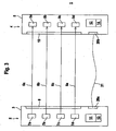
- FIG. 3 shows a third embodiment of a light grid 1.
- the in FIG. 3 illustrated light grid 1 differs from the embodiment according to FIG. 1 only with regard to the design of the interface units. While in the embodiments according to the FIGS. 1 and 2 a non-contact transmission of the parameters, is in the embodiment according to FIG. 3 a wired transmission of the parameters provided.
- a serial interface 20a, b is provided in each case in the transmitter unit 2 and in the receiver unit 4. These serial interfaces 20a, b forming the interface units are connected via a connecting line 21 for the transmission of the parameters.
Landscapes
- Physics & Mathematics (AREA)
- Life Sciences & Earth Sciences (AREA)
- General Life Sciences & Earth Sciences (AREA)
- General Physics & Mathematics (AREA)
- Geophysics (AREA)
- Burglar Alarm Systems (AREA)
- Optical Communication System (AREA)
- Laminated Bodies (AREA)
- Containers Having Bodies Formed In One Piece (AREA)
- Measurement Of The Respiration, Hearing Ability, Form, And Blood Characteristics Of Living Organisms (AREA)
Claims (18)
- Barrière optique pour détecter des objets dans une zone de surveillance, avec une unité émettrice présentant un nombre prédéfini d'émetteurs et une unité réceptrice présentant un nombre prédéfini de récepteurs, des rayons lumineux d'émission émis par les émetteurs étant guidés vers des récepteurs associés lorsque la zone de surveillance est libre, et, en cas d'intrusion d'un objet dans la zone de surveillance, le chemin optique des rayons lumineux d'émission émis par au moins un des émetteurs vers le récepteur associé étant interrompu, ce qui a pour effet de générer une signalisation d'objet dans l'unité réceptrice, caractérisée en ce qu'une unité de mémorisation (13, 14) est prévue chaque fois dans l'unité émettrice (2) et dans l'unité réceptrice (4), des paramètres caractérisant les émetteurs (7a - d) et les récepteurs (9a - d) étant mémorisés dans les deux unités de mémorisation (13, 14) respectives, et qu'une unité d'interface est intégrée chaque fois dans l'unité émettrice (2) et dans l'unité réceptrice (4), les paramètres étant transmissibles entre unité émettrice (2) et unité réceptrice (4) via les unités d'interface.
- Barrière optique selon la revendication 1, caractérisée en ce qu'en cas d'échange de l'unité émettrice (2), les paramètres sont transmissibles de l'unité réceptrice (4) dans la nouvelle unité émettrice (2).
- Barrière optique selon l'une des revendications 1 ou 2, caractérisée en ce qu'en cas d'échange de l'unité réceptrice (4), les paramètres sont transmissibles de l'unité émettrice (2) dans la nouvelle unité réceptrice (4).
- Barrière optique selon l'une des revendications 1 à 3, caractérisée en ce que les unités de mémorisation (13, 14) sont réalisées sous la forme d'unités de mémorisation (13, 14) non volatiles.
- Barrière optique selon l'une des revendications 1 à 4, caractérisée en ce que les paramètres sont mémorisés dans les unités de mémorisation (13, 14) de manière protégée contre les erreurs.
- Barrière optique selon la revendication 5, caractérisée en ce que chaque unité de mémorisation (13, 14) présente une structure à deux canaux.
- Barrière optique selon la revendication 5, caractérisée en ce que la mémorisation des paramètres dans les unités de mémorisation (13, 14) est protégée par des sommes de contrôle.
- Barrière optique selon l'une des revendications 1 à 7, caractérisée en ce que les unités d'interface intégrées dans l'unité émettrice (2) et l'unité réceptrice (4) sont chaque fois formées par un module d'émission et de réception (15a, b) émettant et recevant un signal radio.
- Barrière optique selon l'une des revendications 1 à 7, caractérisée en ce que les unités d'interface intégrées dans l'unité émettrice (2) et l'unité réceptrice (4) sont formées par des interfaces série (20a, b) qui peuvent être reliées par l'intermédiaire d'un câble de liaison.
- Barrière optique selon l'une des revendications 1 à 7, caractérisée en ce que les unités d'interface intégrées dans l'unité émettrice (2) et l'unité réceptrice (4) sont réalisées sous la forme d'unités d'interface optiques.
- Barrière optique selon la revendication 10, caractérisée en ce qu'un émetteur (7a - d) de l'unité émettrice (2) et un récepteur (9a - d) associé à cet émetteur (7a - d) de l'unité réceptrice (4) forment une unité d'interface optique, des paramètres étant transmis de l'unité émettrice (2) dans l'unité réceptrice (4) avec les rayons lumineux d'émission (6a - d) émis par l'émetteur (7a - d).
- Barrière optique selon l'une des revendications 10 ou 11, caractérisée en ce que pour réaliser une unité d'interface optique, un élément émetteur (17) émettant des rayons lumineux (19) est intégré dans l'unité réceptrice (4) et un élément récepteur (18) intégré dans l'unité émettrice (2), des paramètres étant transmis de l'unité réceptrice (4) dans l'unité émettrice (2) avec les rayons lumineux (19) émis par l'élément émetteur (17).
- Barrière optique selon la revendication 12, caractérisée en ce que l'élément émetteur (17) est identique aux émetteurs (7a - d) de l'unité émettrice (2) et que l'élément récepteur (18) est identique aux récepteurs (9a - d) de l'unité réceptrice (4).
- Disposition multiple de barrières optiques selon l'une des revendications 1 à 13, caractérisée en ce que des paramètres sont échangeables entre différentes barrières optiques par l'intermédiaire de l'unité d'interface.
- Disposition multiple de barrières optiques selon la revendication 14, caractérisée en ce que chaque barrière optique présente une unité émettrice et réceptrice dans laquelle sont intégrées des paires d'émetteurs émettant des rayons lumineux d'émission et de récepteurs, et qu'une unité de mémorisation pour mémoriser des paramètres des émetteurs (7a - d) et des récepteurs (9a - d) est prévue dans chaque unité émettrice et réceptrice, et que chaque unité émettrice et réceptrice est intégrée une unité d'interface, les paramètres étant transmissibles par l'intermédiaire des unités d'interface de différentes barrières optiques.
- Disposition multiple de capteurs selon l'une des revendications 1 à 13, caractérisée en ce que chaque capteur présente une unité de mémorisation pour mémoriser des paramètres et une unité d'interface, les paramètres de capteurs étant transmissibles par l'intermédiaire des unités d'interface.
- Disposition multiple de capteurs selon la revendication 16, caractérisée en ce que les capteurs sont réalisés sous des formes différentes.
- Disposition multiple de capteurs selon l'une des revendications 16 ou 17, caractérisée en ce que les capteurs sont des capteurs optiques.
Applications Claiming Priority (1)
| Application Number | Priority Date | Filing Date | Title |
|---|---|---|---|
| DE102006005152A DE102006005152B4 (de) | 2006-02-04 | 2006-02-04 | Lichtschrankenanordnung |
Publications (2)
| Publication Number | Publication Date |
|---|---|
| EP1816487A1 EP1816487A1 (fr) | 2007-08-08 |
| EP1816487B1 true EP1816487B1 (fr) | 2008-11-19 |
Family
ID=38001931
Family Applications (1)
| Application Number | Title | Priority Date | Filing Date |
|---|---|---|---|
| EP07001431A Not-in-force EP1816487B1 (fr) | 2006-02-04 | 2007-01-24 | Barrière optique |
Country Status (4)
| Country | Link |
|---|---|
| US (1) | US20070200699A1 (fr) |
| EP (1) | EP1816487B1 (fr) |
| AT (1) | ATE414920T1 (fr) |
| DE (2) | DE102006005152B4 (fr) |
Cited By (1)
| Publication number | Priority date | Publication date | Assignee | Title |
|---|---|---|---|---|
| DE202010008049U1 (de) | 2010-07-12 | 2011-11-14 | Sick Ag | Sicherheitslichtgitter |
Families Citing this family (13)
| Publication number | Priority date | Publication date | Assignee | Title |
|---|---|---|---|---|
| US7511615B2 (en) * | 2007-01-01 | 2009-03-31 | Intelguard Ltd. | Self-operated perimeter intrusion detection system |
| DE102008009180A1 (de) * | 2007-07-10 | 2009-01-22 | Sick Ag | Optoelektronischer Sensor |
| DE202007015800U1 (de) * | 2007-11-13 | 2009-03-26 | Sick Ag | Sensoranordnung |
| DE102011014195B4 (de) | 2010-03-19 | 2022-04-21 | Leuze Electronic Gmbh & Co. Kg | Optischer Sensor |
| DE102010037681B4 (de) * | 2010-09-21 | 2018-12-27 | Sick Ag | Lichtgitter und Verfahren zur Objektvermessung mit einem Lichtgitter |
| EP2511737B1 (fr) * | 2011-04-13 | 2021-09-15 | Rockwell Automation Switzerland GmbH | Rideau de lumière modulaire et module de plugin correspondant |
| DE102012102069A1 (de) * | 2012-03-12 | 2013-09-12 | Leuze Electronic Gmbh & Co. Kg | Sensoranordnung |
| DE102013112119B4 (de) * | 2013-11-04 | 2020-08-27 | Sick Ag | Lichtgitteranordnung |
| DE102013112483B4 (de) * | 2013-11-13 | 2020-09-24 | Sick Ag | Lichtgitteranordnung |
| DE202020104223U1 (de) | 2020-07-10 | 2021-10-12 | Leuze Electronic Gmbh + Co. Kg | Lichtvorhang |
| DE202022104647U1 (de) | 2022-08-17 | 2023-11-20 | Leuze Electronic Gmbh + Co. Kg | Optischer Sensor |
| DE202022105557U1 (de) * | 2022-09-30 | 2024-01-15 | Leuze Electronic Gmbh + Co. Kg | Sensoranordnung |
| CN115685370B (zh) * | 2022-10-31 | 2026-03-13 | 苏州艾隆科技股份有限公司 | 用于取药装置的检测方法及其装置 |
Family Cites Families (13)
| Publication number | Priority date | Publication date | Assignee | Title |
|---|---|---|---|---|
| US5015840B1 (en) * | 1990-01-09 | 1995-04-11 | Scient Technologies Inc | Self-checking light curtain system and method of operation. |
| JP4052608B2 (ja) * | 1998-06-02 | 2008-02-27 | 株式会社キーエンス | 多光軸光電スイッチ |
| DE19831493C2 (de) * | 1998-07-14 | 2002-03-14 | Leuze Electronic Gmbh & Co | Optoelektronischer Sensor |
| WO2000050267A1 (fr) * | 1999-02-25 | 2000-08-31 | Siemens Aktiengesellschaft | Procede et dispositif pour detecter la presence d'un objet ou d'une personne dans l'habitacle d'un vehicule et dispositif pour assurer la protection des occupants dans un vehicule equipe d'un systeme de ce type |
| US6175419B1 (en) * | 1999-03-24 | 2001-01-16 | Fife Corporation | Light sensor for web-guiding apparatus |
| US6635862B2 (en) * | 2000-03-10 | 2003-10-21 | Scientific Technologies Incorporated | Mixed architecture light curtain system |
| JP3854512B2 (ja) * | 2002-01-25 | 2006-12-06 | 株式会社キーエンス | 多光軸光電式安全装置用の表示モニタ |
| DE10227710B4 (de) * | 2002-06-21 | 2006-04-27 | Leuze Lumiflex Gmbh + Co. Kg | Lichtgitter |
| US7251587B2 (en) * | 2002-08-12 | 2007-07-31 | System To Asic, Inc. | Flexible scanning and sensing platform |
| DE10251350B4 (de) * | 2002-11-05 | 2006-07-20 | Leuze Electronic Gmbh & Co Kg | Optischer Sensor |
| DE10341007B4 (de) * | 2003-09-05 | 2005-12-08 | Leuze Lumiflex Gmbh + Co. Kg | Lichtschrankenanordnung |
| JP4009862B2 (ja) * | 2003-09-30 | 2007-11-21 | オムロン株式会社 | 多光軸光電センサ |
| CH697049A5 (de) * | 2004-07-23 | 2008-03-31 | Baumer Electric Ag | Verfahren und Vorrichtung zur Störungsunterdrückung bei Einweglichtschranken. |
-
2006
- 2006-02-04 DE DE102006005152A patent/DE102006005152B4/de not_active Expired - Fee Related
-
2007
- 2007-01-24 EP EP07001431A patent/EP1816487B1/fr not_active Not-in-force
- 2007-01-24 AT AT07001431T patent/ATE414920T1/de active
- 2007-01-24 DE DE502007000235T patent/DE502007000235D1/de active Active
- 2007-02-05 US US11/702,169 patent/US20070200699A1/en not_active Abandoned
Cited By (1)
| Publication number | Priority date | Publication date | Assignee | Title |
|---|---|---|---|---|
| DE202010008049U1 (de) | 2010-07-12 | 2011-11-14 | Sick Ag | Sicherheitslichtgitter |
Also Published As
| Publication number | Publication date |
|---|---|
| ATE414920T1 (de) | 2008-12-15 |
| DE102006005152A1 (de) | 2007-08-30 |
| US20070200699A1 (en) | 2007-08-30 |
| DE502007000235D1 (de) | 2009-01-02 |
| DE102006005152B4 (de) | 2008-10-02 |
| EP1816487A1 (fr) | 2007-08-08 |
Similar Documents
| Publication | Publication Date | Title |
|---|---|---|
| EP1816487B1 (fr) | Barrière optique | |
| EP3069202B1 (fr) | Commande de sécurité à entrées configurables | |
| EP1933174B1 (fr) | Barrière lumineuse | |
| EP1398729B1 (fr) | Système de détecteur et procédé de détection | |
| DE10312972B3 (de) | Optischer Sensor | |
| EP1923726A2 (fr) | Capteur optique | |
| WO2003040755A1 (fr) | Reseau de lumiere laser destine a la mesure de distance | |
| EP1443343B1 (fr) | Détecteur optique avec plusiers sorties de commutation | |
| EP2843447B1 (fr) | Barrière lumineuse | |
| EP3217195B1 (fr) | Capteur optique | |
| DE102007035248B4 (de) | Sensor | |
| DE102006054124B4 (de) | Verfahren und System zur sicheren Datenübertragung | |
| DE102007055521B4 (de) | Vorrichtung zur Überwachung eines Überwachungsbereichs | |
| EP3133331B1 (fr) | Systeme de securite et procede de surveillance | |
| DE102010024611B4 (de) | Sensoranordnung | |
| EP1895329A2 (fr) | Dispositif destiné à la saisie d'objets dans une zone de surveillance | |
| DE19861128B4 (de) | Optischer Türwächter | |
| EP2639603A2 (fr) | Dispositif de détection | |
| DE19815148B4 (de) | Sensoranordnung | |
| DE202009000776U1 (de) | Sicherheits-Lichtgitter | |
| DE102007009141A1 (de) | Sicherheitsvorrichtung und Sicherheitsverfahren mit mehreren Verarbeitungsstufen | |
| DE10155582B4 (de) | Schaltungsanordnung | |
| EP3879312B1 (fr) | Capteur optique | |
| DE102018116264B4 (de) | Lichtgitter | |
| DE202022103777U1 (de) | Überwachungseinrichtung |
Legal Events
| Date | Code | Title | Description |
|---|---|---|---|
| PUAI | Public reference made under article 153(3) epc to a published international application that has entered the european phase |
Free format text: ORIGINAL CODE: 0009012 |
|
| AK | Designated contracting states |
Kind code of ref document: A1 Designated state(s): AT BE BG CH CY CZ DE DK EE ES FI FR GB GR HU IE IS IT LI LT LU LV MC NL PL PT RO SE SI SK TR |
|
| AX | Request for extension of the european patent |
Extension state: AL BA HR MK RS |
|
| 17P | Request for examination filed |
Effective date: 20070703 |
|
| 17Q | First examination report despatched |
Effective date: 20071004 |
|
| AKX | Designation fees paid |
Designated state(s): AT BE BG CH CY CZ DE DK EE ES FI FR GB GR HU IE IS IT LI LT LU LV MC NL PL PT RO SE SI SK TR |
|
| GRAP | Despatch of communication of intention to grant a patent |
Free format text: ORIGINAL CODE: EPIDOSNIGR1 |
|
| GRAS | Grant fee paid |
Free format text: ORIGINAL CODE: EPIDOSNIGR3 |
|
| GRAA | (expected) grant |
Free format text: ORIGINAL CODE: 0009210 |
|
| AK | Designated contracting states |
Kind code of ref document: B1 Designated state(s): AT BE BG CH CY CZ DE DK EE ES FI FR GB GR HU IE IS IT LI LT LU LV MC NL PL PT RO SE SI SK TR |
|
| REG | Reference to a national code |
Ref country code: GB Ref legal event code: FG4D Free format text: NOT ENGLISH |
|
| REG | Reference to a national code |
Ref country code: CH Ref legal event code: EP |
|
| REG | Reference to a national code |
Ref country code: IE Ref legal event code: FG4D Free format text: LANGUAGE OF EP DOCUMENT: GERMAN |
|
| REG | Reference to a national code |
Ref country code: CH Ref legal event code: NV Representative=s name: ROTTMANN, ZIMMERMANN + PARTNER AG |
|
| REF | Corresponds to: |
Ref document number: 502007000235 Country of ref document: DE Date of ref document: 20090102 Kind code of ref document: P |
|
| LTIE | Lt: invalidation of european patent or patent extension |
Effective date: 20081119 |
|
| PG25 | Lapsed in a contracting state [announced via postgrant information from national office to epo] |
Ref country code: LT Free format text: LAPSE BECAUSE OF FAILURE TO SUBMIT A TRANSLATION OF THE DESCRIPTION OR TO PAY THE FEE WITHIN THE PRESCRIBED TIME-LIMIT Effective date: 20081119 Ref country code: ES Free format text: LAPSE BECAUSE OF FAILURE TO SUBMIT A TRANSLATION OF THE DESCRIPTION OR TO PAY THE FEE WITHIN THE PRESCRIBED TIME-LIMIT Effective date: 20090301 |
|
| NLV1 | Nl: lapsed or annulled due to failure to fulfill the requirements of art. 29p and 29m of the patents act | ||
| PG25 | Lapsed in a contracting state [announced via postgrant information from national office to epo] |
Ref country code: LV Free format text: LAPSE BECAUSE OF FAILURE TO SUBMIT A TRANSLATION OF THE DESCRIPTION OR TO PAY THE FEE WITHIN THE PRESCRIBED TIME-LIMIT Effective date: 20081119 Ref country code: PL Free format text: LAPSE BECAUSE OF FAILURE TO SUBMIT A TRANSLATION OF THE DESCRIPTION OR TO PAY THE FEE WITHIN THE PRESCRIBED TIME-LIMIT Effective date: 20081119 Ref country code: SI Free format text: LAPSE BECAUSE OF FAILURE TO SUBMIT A TRANSLATION OF THE DESCRIPTION OR TO PAY THE FEE WITHIN THE PRESCRIBED TIME-LIMIT Effective date: 20081119 Ref country code: NL Free format text: LAPSE BECAUSE OF FAILURE TO SUBMIT A TRANSLATION OF THE DESCRIPTION OR TO PAY THE FEE WITHIN THE PRESCRIBED TIME-LIMIT Effective date: 20081119 Ref country code: FI Free format text: LAPSE BECAUSE OF FAILURE TO SUBMIT A TRANSLATION OF THE DESCRIPTION OR TO PAY THE FEE WITHIN THE PRESCRIBED TIME-LIMIT Effective date: 20081119 Ref country code: IS Free format text: LAPSE BECAUSE OF FAILURE TO SUBMIT A TRANSLATION OF THE DESCRIPTION OR TO PAY THE FEE WITHIN THE PRESCRIBED TIME-LIMIT Effective date: 20090319 |
|
| REG | Reference to a national code |
Ref country code: IE Ref legal event code: FD4D |
|
| PG25 | Lapsed in a contracting state [announced via postgrant information from national office to epo] |
Ref country code: IE Free format text: LAPSE BECAUSE OF FAILURE TO SUBMIT A TRANSLATION OF THE DESCRIPTION OR TO PAY THE FEE WITHIN THE PRESCRIBED TIME-LIMIT Effective date: 20081119 Ref country code: EE Free format text: LAPSE BECAUSE OF FAILURE TO SUBMIT A TRANSLATION OF THE DESCRIPTION OR TO PAY THE FEE WITHIN THE PRESCRIBED TIME-LIMIT Effective date: 20081119 Ref country code: RO Free format text: LAPSE BECAUSE OF FAILURE TO SUBMIT A TRANSLATION OF THE DESCRIPTION OR TO PAY THE FEE WITHIN THE PRESCRIBED TIME-LIMIT Effective date: 20081119 Ref country code: BG Free format text: LAPSE BECAUSE OF FAILURE TO SUBMIT A TRANSLATION OF THE DESCRIPTION OR TO PAY THE FEE WITHIN THE PRESCRIBED TIME-LIMIT Effective date: 20090219 Ref country code: DK Free format text: LAPSE BECAUSE OF FAILURE TO SUBMIT A TRANSLATION OF THE DESCRIPTION OR TO PAY THE FEE WITHIN THE PRESCRIBED TIME-LIMIT Effective date: 20081119 |
|
| PG25 | Lapsed in a contracting state [announced via postgrant information from national office to epo] |
Ref country code: PT Free format text: LAPSE BECAUSE OF FAILURE TO SUBMIT A TRANSLATION OF THE DESCRIPTION OR TO PAY THE FEE WITHIN THE PRESCRIBED TIME-LIMIT Effective date: 20090420 Ref country code: MC Free format text: LAPSE BECAUSE OF NON-PAYMENT OF DUE FEES Effective date: 20090131 Ref country code: SE Free format text: LAPSE BECAUSE OF FAILURE TO SUBMIT A TRANSLATION OF THE DESCRIPTION OR TO PAY THE FEE WITHIN THE PRESCRIBED TIME-LIMIT Effective date: 20090219 Ref country code: CZ Free format text: LAPSE BECAUSE OF FAILURE TO SUBMIT A TRANSLATION OF THE DESCRIPTION OR TO PAY THE FEE WITHIN THE PRESCRIBED TIME-LIMIT Effective date: 20081119 |
|
| PLBE | No opposition filed within time limit |
Free format text: ORIGINAL CODE: 0009261 |
|
| STAA | Information on the status of an ep patent application or granted ep patent |
Free format text: STATUS: NO OPPOSITION FILED WITHIN TIME LIMIT |
|
| PG25 | Lapsed in a contracting state [announced via postgrant information from national office to epo] |
Ref country code: SK Free format text: LAPSE BECAUSE OF FAILURE TO SUBMIT A TRANSLATION OF THE DESCRIPTION OR TO PAY THE FEE WITHIN THE PRESCRIBED TIME-LIMIT Effective date: 20081119 |
|
| 26N | No opposition filed |
Effective date: 20090820 |
|
| PG25 | Lapsed in a contracting state [announced via postgrant information from national office to epo] |
Ref country code: BE Free format text: LAPSE BECAUSE OF NON-PAYMENT OF DUE FEES Effective date: 20090131 |
|
| PG25 | Lapsed in a contracting state [announced via postgrant information from national office to epo] |
Ref country code: GR Free format text: LAPSE BECAUSE OF FAILURE TO SUBMIT A TRANSLATION OF THE DESCRIPTION OR TO PAY THE FEE WITHIN THE PRESCRIBED TIME-LIMIT Effective date: 20090220 |
|
| PG25 | Lapsed in a contracting state [announced via postgrant information from national office to epo] |
Ref country code: IT Free format text: LAPSE BECAUSE OF FAILURE TO SUBMIT A TRANSLATION OF THE DESCRIPTION OR TO PAY THE FEE WITHIN THE PRESCRIBED TIME-LIMIT Effective date: 20081119 |
|
| PG25 | Lapsed in a contracting state [announced via postgrant information from national office to epo] |
Ref country code: LU Free format text: LAPSE BECAUSE OF NON-PAYMENT OF DUE FEES Effective date: 20090124 |
|
| PG25 | Lapsed in a contracting state [announced via postgrant information from national office to epo] |
Ref country code: HU Free format text: LAPSE BECAUSE OF FAILURE TO SUBMIT A TRANSLATION OF THE DESCRIPTION OR TO PAY THE FEE WITHIN THE PRESCRIBED TIME-LIMIT Effective date: 20090520 |
|
| PG25 | Lapsed in a contracting state [announced via postgrant information from national office to epo] |
Ref country code: TR Free format text: LAPSE BECAUSE OF FAILURE TO SUBMIT A TRANSLATION OF THE DESCRIPTION OR TO PAY THE FEE WITHIN THE PRESCRIBED TIME-LIMIT Effective date: 20081119 |
|
| REG | Reference to a national code |
Ref country code: CH Ref legal event code: PFA Owner name: LEUZE LUMIFLEX GMBH + CO. KG Free format text: LEUZE LUMIFLEX GMBH + CO. KG#LIEBIGSTRASSE 4#82256 FUERSTENFELDBRUCK (DE) -TRANSFER TO- LEUZE LUMIFLEX GMBH + CO. KG#LIEBIGSTRASSE 4#82256 FUERSTENFELDBRUCK (DE) |
|
| GBPC | Gb: european patent ceased through non-payment of renewal fee |
Effective date: 20110124 |
|
| PG25 | Lapsed in a contracting state [announced via postgrant information from national office to epo] |
Ref country code: CY Free format text: LAPSE BECAUSE OF FAILURE TO SUBMIT A TRANSLATION OF THE DESCRIPTION OR TO PAY THE FEE WITHIN THE PRESCRIBED TIME-LIMIT Effective date: 20081119 |
|
| PG25 | Lapsed in a contracting state [announced via postgrant information from national office to epo] |
Ref country code: GB Free format text: LAPSE BECAUSE OF NON-PAYMENT OF DUE FEES Effective date: 20110124 |
|
| PGFP | Annual fee paid to national office [announced via postgrant information from national office to epo] |
Ref country code: AT Payment date: 20140113 Year of fee payment: 8 |
|
| REG | Reference to a national code |
Ref country code: AT Ref legal event code: MM01 Ref document number: 414920 Country of ref document: AT Kind code of ref document: T Effective date: 20150124 |
|
| PG25 | Lapsed in a contracting state [announced via postgrant information from national office to epo] |
Ref country code: AT Free format text: LAPSE BECAUSE OF NON-PAYMENT OF DUE FEES Effective date: 20150124 |
|
| REG | Reference to a national code |
Ref country code: FR Ref legal event code: PLFP Year of fee payment: 10 |
|
| REG | Reference to a national code |
Ref country code: CH Ref legal event code: PCAR Free format text: NEW ADDRESS: GARTENSTRASSE 28 A, 5400 BADEN (CH) |
|
| REG | Reference to a national code |
Ref country code: FR Ref legal event code: PLFP Year of fee payment: 11 |
|
| REG | Reference to a national code |
Ref country code: FR Ref legal event code: PLFP Year of fee payment: 12 |
|
| PGFP | Annual fee paid to national office [announced via postgrant information from national office to epo] |
Ref country code: CH Payment date: 20180119 Year of fee payment: 12 |
|
| PGFP | Annual fee paid to national office [announced via postgrant information from national office to epo] |
Ref country code: FR Payment date: 20180119 Year of fee payment: 12 |
|
| PGFP | Annual fee paid to national office [announced via postgrant information from national office to epo] |
Ref country code: DE Payment date: 20190116 Year of fee payment: 13 |
|
| PGFP | Annual fee paid to national office [announced via postgrant information from national office to epo] |
Ref country code: DE Payment date: 20190116 Year of fee payment: 13 |
|
| REG | Reference to a national code |
Ref country code: CH Ref legal event code: PL |
|
| PG25 | Lapsed in a contracting state [announced via postgrant information from national office to epo] |
Ref country code: FR Free format text: LAPSE BECAUSE OF NON-PAYMENT OF DUE FEES Effective date: 20190131 |
|
| PG25 | Lapsed in a contracting state [announced via postgrant information from national office to epo] |
Ref country code: CH Free format text: LAPSE BECAUSE OF NON-PAYMENT OF DUE FEES Effective date: 20190131 Ref country code: LI Free format text: LAPSE BECAUSE OF NON-PAYMENT OF DUE FEES Effective date: 20190131 |
|
| REG | Reference to a national code |
Ref country code: DE Ref legal event code: R119 Ref document number: 502007000235 Country of ref document: DE |
|
| PG25 | Lapsed in a contracting state [announced via postgrant information from national office to epo] |
Ref country code: DE Free format text: LAPSE BECAUSE OF NON-PAYMENT OF DUE FEES Effective date: 20200801 |