EP1895329A2 - Dispositif destiné à la saisie d'objets dans une zone de surveillance - Google Patents
Dispositif destiné à la saisie d'objets dans une zone de surveillance Download PDFInfo
- Publication number
- EP1895329A2 EP1895329A2 EP07014249A EP07014249A EP1895329A2 EP 1895329 A2 EP1895329 A2 EP 1895329A2 EP 07014249 A EP07014249 A EP 07014249A EP 07014249 A EP07014249 A EP 07014249A EP 1895329 A2 EP1895329 A2 EP 1895329A2
- Authority
- EP
- European Patent Office
- Prior art keywords
- sensor
- configuration module
- machine
- configuration
- configuration data
- Prior art date
- Legal status (The legal status is an assumption and is not a legal conclusion. Google has not performed a legal analysis and makes no representation as to the accuracy of the status listed.)
- Withdrawn
Links
- 238000012544 monitoring process Methods 0.000 claims abstract description 16
- 230000003287 optical effect Effects 0.000 claims description 39
- 238000009434 installation Methods 0.000 claims description 5
- 238000000465 moulding Methods 0.000 abstract 1
- 238000001514 detection method Methods 0.000 description 9
- 238000011156 evaluation Methods 0.000 description 7
- 230000006870 function Effects 0.000 description 5
- 238000000034 method Methods 0.000 description 4
- 230000008901 benefit Effects 0.000 description 2
- 230000007547 defect Effects 0.000 description 2
- 230000002950 deficient Effects 0.000 description 2
- 231100001261 hazardous Toxicity 0.000 description 2
- 230000004913 activation Effects 0.000 description 1
- 230000008878 coupling Effects 0.000 description 1
- 238000010168 coupling process Methods 0.000 description 1
- 238000005859 coupling reaction Methods 0.000 description 1
- 238000011161 development Methods 0.000 description 1
- 230000018109 developmental process Effects 0.000 description 1
- 230000010354 integration Effects 0.000 description 1
- 230000007257 malfunction Effects 0.000 description 1
- 238000005259 measurement Methods 0.000 description 1
- 230000008569 process Effects 0.000 description 1
- 238000012546 transfer Methods 0.000 description 1
- 238000011144 upstream manufacturing Methods 0.000 description 1
Images


Classifications
-
- G—PHYSICS
- G01—MEASURING; TESTING
- G01V—GEOPHYSICS; GRAVITATIONAL MEASUREMENTS; DETECTING MASSES OR OBJECTS; TAGS
- G01V8/00—Prospecting or detecting by optical means
- G01V8/10—Detecting, e.g. by using light barriers
Definitions
- the invention relates to a device for detecting objects in a surveillance area.
- the object detection takes place by means of a sensor.
- this In order to be able to use the respective sensor for a specific application, such as, for example, the implementation of specific monitoring functions on machines and systems, this must be parameterized in a predefined manner. If, in the event of a defect in a sensor, a replacement of this sensor with a new one is required, the new sensor must be parameterized identically. This generally requires not only a considerable amount of time, but in principle also constitutes a source of error. If a parameterization by an operator is not carried out carefully, so that the parameterization of the new sensor does not completely match that of the old sensor to be replaced, then it can operate during operation of the new sensor Sensors come to malfunction.
- a method of configuring sensors in which configuration data containing an existing configuration of a sensor is transferred from an output sensor to a sensor to be configured is known.
- the output sensor in the unconfigured or in the configured state is connected to a module which stores the current configuration of the output sensor as well as a checksum corresponding to the configuration data.
- the module is connected to the sensor to be configured, the data stored in the module are read into the sensor to be configured and a check sum corresponding to the read-in data is calculated, whereupon the calculated checksum in the module is compared with the checksum stored in the module and an error message is generated if the two checksums do not match.
- An advantage of this method is that the module used configuration data can be completely transferred from one sensor to another, which greatly facilitates the parameterization of a sensor.
- a disadvantage of this method is that it is the operator, which is reserved for the parameterization of the sensor, from which sensor configuration data are read to store them in each module. This represents a considerable source of error, since different sensors for different applications can be confused during the parameterization by means of the module. This is particularly disadvantageous in applications in which sensors are used for monitoring functions in complex machines and systems. There, a plurality of sensors is used, wherein the individual sensors must fulfill different monitoring functions and therefore must be parameterized in different ways.
- the invention has for its object to provide a simple, fail-safe parameterization for sensors.
- the device has at least one sensor for detecting objects within a monitoring area assigned to a machine or installation.
- At least one configuration module is permanently connected to the machine or system, in which configuration data for the sensor are stored. When the sensor is connected to the configuration module, the configuration data from it can be read into the sensor.
- a significant advantage of the device according to the invention is that there is a fixed mechanical connection of a configuration module containing configuration data to a system or machine. This results in a fixed assignment of configuration data contained in the configuration module, in particular machine or plant-specific configuration data to the respective system of the machine. Due to this fixed allocation, confusion in the parameterization, that is, configuration of sensors with high security, is excluded.
- To parameterize a sensor it is connected directly to the configuration module connected to the machine or system so that the sensor can take over the configuration data from this configuration module. Since the sensor is thus configured at the place of use on the machine or system by means of the configuration module, a transfer of configuration data that is not adapted to the machine or system is excluded with great certainty.
- the defective sensor only needs to be removed from the configuration module and replaced there by the new sensor.
- the new sensor then takes over the configuration data from the configuration module in the same way as the old sensor, which ensures that the new sensor has the same configuration as the old sensor.
- the fixed mechanical connection between the configuration module and the machine or system ensures that the new and the old sensor receive the correct configuration data adapted to the machine or system.
- the respective configuration data can be read in and stored in the configuration module before the device is put into operation.
- the sensor connected to the configuration module then takes over the configuration data from the configuration module.
- the new sensor can then adopt the configuration data of the old sensor.
- the fixed mechanical assignment of the configuration module to the respective machine is realized particularly advantageously by a cable connection, wherein the configuration module is integrated in the cable itself or in a plug attached to the cable.
- the integration of the configuration module in a cable or plug represents a particularly simple and space-saving attachment of the configuration module.
- the configuration module can also have a bus connection, so that the configuration module is firmly connected to the respective machine or system via a bus system.
- This embodiment is suitable in particular for complex applications, for example for installations in which a large number of sensors are required for monitoring purposes.
- the configuration module can be integrated to save space in a plug.
- the device comprises a configuration module which is mechanically fixedly connected to a machine or system.
- a plurality of configuration modules each coupled to them via a fixed mechanical connection such as a cable, can also be provided on a machine or system, in which specific configuration data are stored by means of which sensors to be connected there can be configured.
- specific configuration data are stored by means of which sensors to be connected there can be configured.
- different, preferably machine or installation-specific configuration data can be stored in the individual configuration modules, so that the sensors can be individually configured according to their location on the machine or system.
- the sensors are designed in particular as optical sensors, in particular area distance sensors or light grids.
- the sensors thereby form safety sensors, which are designed so that they can be used in the field of personal safety.
- FIG. 1 schematically shows a device 1 for securing hazardous areas on a machine 2.
- the machine 2 can be designed as a press or the like, whereby danger to persons can generally arise within a danger zone in advance of the machine 2 due to its working movements.
- the danger zone is monitored by means of an optical sensor 3.
- an object detection takes place within a monitoring area 4 whose size is adapted to the extent of the danger zone. If an object intervention is registered by means of the optical sensor 3 within the monitoring area, a corresponding object detection signal is generated in the optical sensor 3 generated, which serves as a control signal for the machine 2 such that the machine 2 is switched off to avoid danger.
- a cable connection is provided for coupling the optical sensor 3 to the machine.
- a connector 5 is provided for connecting a cable 6.
- a plug 7 for connection of the optical sensor 3 is provided at the free end of the cable 6, a plug 7 for connection of the optical sensor 3 is provided.
- the optical sensor 3 has for this purpose a socket 8 or the like, which can be contacted with the plug 7.
- the configuration module 9 essentially comprises a memory unit, which is preferably formed by a non-volatile memory. Alternatively, the configuration module 9 can be integrated directly in the cable 6.
- the configuration module 9 is formed solely by a non-volatile data memory such as an EEPROM, that is to say without its own intelligence, that is to say without its own computer unit.
- a non-volatile data memory such as an EEPROM
- the reading or reading in of data thus takes place via the integrated in the optical sensor 3 computer units.
- the non-volatile data memory is thereby read or written by a standard memory interface, wherein the interface for this preferably has four pins for transmitting the supply voltage and the data and for a clock line to the data memory.
- configuration data are stored. These configuration data contain data specific to the given application, in the present case for hazardous area protection on the machine 2, which define and define the operation of the optical sensor 3.
- the configuration of the optical sensor 3 can thus be carried out automatically when connected to the plug 7. As soon as the contact of the optical sensor 3 to the plug 7 has been established, the optical sensor 3 takes over the configuration data from the configuration module 9 and is therefore ready for operation without any further adjustment processes. Preferably, this is checked after switching on the optical sensor 3 in this, whether a configuration memory is connected or not. Accordingly, after switching on the optical sensor 3, data from the configuration module 9 is read in or out of the integrated computer units. Due to the mechanical connection of the configuration module 9 to the machine 2, a fixed assignment of the configuration module 9 to the machine 2 is given. As a result, a faulty configuration of the optical sensor 3 is excluded. In particular, can be excluded by the fixed assignment of the configuration module 9 to the machine confusion in the configuration of optical sensors 3.
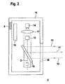
- FIG. 2 shows an embodiment of the optical sensor 3 which can be used for the device according to FIG.
- the optical sensor 3 is designed as a surface distance sensor.
- the area distance sensor is integrated in a housing 10, wherein in a housing wall the Socket 8 is integrated to connect the plug 7.
- the area distance sensor comprises, as a distance sensor element, a transmitter 12 emitting transmitted light beams 11 and a receiver 14 receiving receiving light beams 13 as a light receiving unit.
- the distance measurement takes place, for example, according to the transit time principle, that is to say the transmitter 12 emits transmitted light in the form of short light pulses whose transit times to an object to be detected and back to the receiver 14 are registered and evaluated as a measure of the object distance.
- the evaluation of the received signals present at the output of the receiver 14 takes place in an evaluation unit 15.
- the optical sensor 3 has a redundantly constructed evaluation unit 15, for example in the form of two micro-controllers monitoring each other cyclically.
- the sensor 3 thus forms a safety sensor.
- the optical sensor 3 comprises a deflection unit in the form of a motor-driven deflection mirror 16 which is rotatable about a rotation axis D.
- the transmitter 12 and the receiver 14 are arranged lying in the axis of rotation D, wherein a receiving optical system 17 is arranged upstream of the receiver 14.
- the transmitted light beams 11 and the received light beams 12 are deflected by the deflection mirror 16 and thus periodically guided within an in-plane detection area.
- the swept by the transmitted light beams 11 angle range and thus the size of the detection range can be specified by a suitable dimensioning of the width of an exit window 18 in the housing 10, through which the transmitted light beams 11 and received light beams 13 are performed.
- a protection zone forming the monitoring area 4 can be defined.
- the protection zone may be defined by parameter values formed, for example, by the edges of the protection zone.
- the operation of the area distance sensor then takes place such that in the evaluation unit 15 as a function of whether within the protection zone an object is detected or not, as an object detection signal, a binary switching signal is generated, which is used to control the machine 2. In this case, the machine 2 is switched off when an object is detected within the protection zone.
- the parameters defining the protection zone form machine-specific configuration data, which are stored in the configuration module 9 and are read out of the configuration module 9 when the optical sensor 3 is connected to the plug 7.
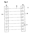
- FIG. 3 schematically shows an optical sensor 3 embodied as a light grid.
- the light grid comprises a series arrangement of light beams 19 emitting transmitting elements 20 in a first housing 21 and a corresponding series arrangement of light beams receiving receiving elements 22 in a second housing 23.
- the transmitting elements 20 are preferably cyclically activates a transmitting unit, not shown, the receiver 14 are cyclically activated in the same clock via a receiver unit.
- the synchronization of the transmitter and receiver activation takes place optically via the guided by the transmitting elements 20 to the receiving elements 22 light rays 19.
- the light beams 19 are each a transmitting element 20 to the opposite receiving element 22 out.
- the pairs of transmitting elements 20 and receiving elements 22 thus formed form beam axes of the light grid, the light beams 19 of the beam axes forming the detection area within which objects can be detected.
- the generation of an object detection signal takes place in the receiver unit as a function of the received signals at the outputs of the receiver elements 22.
- An object is considered to be detected if at least one of the beam axes is inhibited.
- the receiver unit thus forms an evaluation unit 15 for evaluating the received signals of the light grid.
- the light grid is designed as a safety sensor.
- the Evaluation unit 15 to a redundant structure, preferably in the form of two mutually cyclically monitoring microcontroller.
- the monitoring area 4 can be formed by all the beam axes of the light grid or only part of the beam axes.
- the light grid is blanked in such a way that certain beam axes are deactivated in such a way that an object intervention within these beam axes does not lead to an object message and thus to a shutdown of the machine 2.
- the specification of such blanking areas is performed by parameter values that can be stored as configuration data in the configuration module 9.
- the socket 8 serving to connect the plug 7 to the configuration module 9 is integrated in a housing wall of the housing 23.
- FIG. 4 shows a variant of the device 1 according to FIG. 1.
- a configuration module 9 integrated in a plug 7 is also connected to a machine 2 via a fixed mechanical connection in the exemplary embodiment according to FIG.
- an optical sensor 3 can be connected to the plug 7, which is used for danger zone monitoring and which has a socket 8 for connection to the plug 7.
- configuration data from the configuration module 9 are in turn transmitted to the optical sensor 3 in order to configure the optical sensor 3.
- a connection between the configuration module 9 and the machine 2 is established by means of bus lines 24.
- a bus connection 25 for connection to the bus lines 24 is provided in the plug 7.
- the machine 2 and the connected via the plug 7 optical sensor 3 thus form participants of a bus system.
- the configuration according to FIG. 4 is suitable in particular for complex systems, in which possibly a plurality of optical systems Sensors 3 are used to monitor one or more machines or systems.
Landscapes
- Physics & Mathematics (AREA)
- Life Sciences & Earth Sciences (AREA)
- General Life Sciences & Earth Sciences (AREA)
- General Physics & Mathematics (AREA)
- Geophysics (AREA)
- Testing Or Calibration Of Command Recording Devices (AREA)
- Burglar Alarm Systems (AREA)
- Geophysics And Detection Of Objects (AREA)
Applications Claiming Priority (1)
| Application Number | Priority Date | Filing Date | Title |
|---|---|---|---|
| DE102006041251.6A DE102006041251C5 (de) | 2006-09-02 | 2006-09-02 | Vorrichtung zur Erfassung von Objekten in einem Überwachungsbereich |
Publications (2)
| Publication Number | Publication Date |
|---|---|
| EP1895329A2 true EP1895329A2 (fr) | 2008-03-05 |
| EP1895329A3 EP1895329A3 (fr) | 2013-02-13 |
Family
ID=38962923
Family Applications (1)
| Application Number | Title | Priority Date | Filing Date |
|---|---|---|---|
| EP07014249A Withdrawn EP1895329A3 (fr) | 2006-09-02 | 2007-07-20 | Dispositif destiné à la saisie d'objets dans une zone de surveillance |
Country Status (3)
| Country | Link |
|---|---|
| US (1) | US7696468B2 (fr) |
| EP (1) | EP1895329A3 (fr) |
| DE (1) | DE102006041251C5 (fr) |
Cited By (1)
| Publication number | Priority date | Publication date | Assignee | Title |
|---|---|---|---|---|
| EP2333802A3 (fr) * | 2009-12-08 | 2012-09-26 | Link GmbH | Unité de capteur et système de surveillance de bâtiment doté de telles unités de capteur |
Families Citing this family (3)
| Publication number | Priority date | Publication date | Assignee | Title |
|---|---|---|---|---|
| EP1469903A2 (fr) * | 2001-09-28 | 2004-10-27 | BioValve Technologies, Inc. | Micro-aiguille a membrane |
| DK2106560T3 (en) * | 2007-01-24 | 2017-08-07 | Ravenbrick Llc | THERMAL REPLACED OPTICAL DOWN CONVERTER FILTER |
| EP2544591B1 (fr) | 2010-03-08 | 2021-07-21 | Masimo Corporation | Retraitement d'un capteur physiologique |
Citations (4)
| Publication number | Priority date | Publication date | Assignee | Title |
|---|---|---|---|---|
| DE4114921A1 (de) | 1991-05-07 | 1992-11-12 | Ahlborn Mess Und Regelungstech | Elektrische steckverbindung |
| EP0936442A1 (fr) | 1998-02-12 | 1999-08-18 | Schmersal-EOT GmbH & Co. KG | Méthode de configuration des capteurs |
| EP1300657A2 (fr) | 2001-10-08 | 2003-04-09 | AVL List GmbH | Capteur avec une unité de mémoire externe |
| DE10211941A1 (de) | 2002-03-18 | 2003-10-16 | Sick Ag | Sensor-Maschinen-Interface und Verfahren zu dessen Betrieb |
Family Cites Families (8)
| Publication number | Priority date | Publication date | Assignee | Title |
|---|---|---|---|---|
| US5736930A (en) * | 1995-07-21 | 1998-04-07 | Apple Computer, Inc. | Apparatus and method for radiation source failure prediction |
| DE19809709A1 (de) * | 1998-03-06 | 1999-09-09 | Sick Ag | Vorrichtung zum Überwachen eines Schutzbereichs |
| DE20215631U1 (de) * | 2002-10-11 | 2003-02-06 | Sick AG, 79183 Waldkirch | Sensor |
| DE10254010B4 (de) * | 2002-11-19 | 2009-01-02 | Siemens Ag | Verfahren zur automatischen Konfiguration einer Parametrieroberfläche von Werkzeugmaschinen oder Produktionsmaschinen |
| DE102005003254B4 (de) * | 2005-01-24 | 2007-10-04 | Sick Ag | Optoelektronischer Sensor und Konfigurationsverfahren |
| DE202005002797U1 (de) * | 2005-02-22 | 2005-08-04 | Fiessler Elektronik Gmbh & Co. Kg | Sicherheitseinrichtung für maschinelle Vorrichtungen, insbesondere für Bearbeitungsmaschinen oder Fördereinrichtungen |
| DE102005049483B4 (de) * | 2005-10-13 | 2007-10-18 | Ifm Electronic Gmbh | Elektrischen Stecker und Verfahren zur dezentralen Speicherung der Parameter eines Sensors |
| DE102007029423B4 (de) * | 2007-06-26 | 2009-09-03 | Sick Ag | Steuerungssystem |
-
2006
- 2006-09-02 DE DE102006041251.6A patent/DE102006041251C5/de active Active
-
2007
- 2007-07-20 EP EP07014249A patent/EP1895329A3/fr not_active Withdrawn
- 2007-09-04 US US11/896,572 patent/US7696468B2/en active Active
Patent Citations (4)
| Publication number | Priority date | Publication date | Assignee | Title |
|---|---|---|---|---|
| DE4114921A1 (de) | 1991-05-07 | 1992-11-12 | Ahlborn Mess Und Regelungstech | Elektrische steckverbindung |
| EP0936442A1 (fr) | 1998-02-12 | 1999-08-18 | Schmersal-EOT GmbH & Co. KG | Méthode de configuration des capteurs |
| EP1300657A2 (fr) | 2001-10-08 | 2003-04-09 | AVL List GmbH | Capteur avec une unité de mémoire externe |
| DE10211941A1 (de) | 2002-03-18 | 2003-10-16 | Sick Ag | Sensor-Maschinen-Interface und Verfahren zu dessen Betrieb |
Cited By (1)
| Publication number | Priority date | Publication date | Assignee | Title |
|---|---|---|---|---|
| EP2333802A3 (fr) * | 2009-12-08 | 2012-09-26 | Link GmbH | Unité de capteur et système de surveillance de bâtiment doté de telles unités de capteur |
Also Published As
| Publication number | Publication date |
|---|---|
| DE102006041251A1 (de) | 2008-03-13 |
| DE102006041251C5 (de) | 2016-04-14 |
| DE102006041251B4 (de) | 2009-12-17 |
| US7696468B2 (en) | 2010-04-13 |
| US20080061221A1 (en) | 2008-03-13 |
| EP1895329A3 (fr) | 2013-02-13 |
Similar Documents
| Publication | Publication Date | Title |
|---|---|---|
| EP1816487B1 (fr) | Barrière optique | |
| EP2691969B1 (fr) | Ensemble de circuit de sécurité pour mettre sous ou hors tension de manière sécurisée une installation dangereuse | |
| EP2012201A1 (fr) | Procédé destiné à la programmation d'une commande de sécurité | |
| DE102007057376A1 (de) | Drehgeber mit interner Fehlerkontrolle und Verfahren hierzu | |
| EP2843447B1 (fr) | Barrière lumineuse | |
| EP3538962A1 (fr) | Procédé d'analyse de dysfonctionnements dans une installation de l'automatisation de processus | |
| EP1895329A2 (fr) | Dispositif destiné à la saisie d'objets dans une zone de surveillance | |
| EP1923726A2 (fr) | Capteur optique | |
| DE102007055521B4 (de) | Vorrichtung zur Überwachung eines Überwachungsbereichs | |
| DE10251350B4 (de) | Optischer Sensor | |
| DE102007035248A1 (de) | Sensor | |
| EP4432034B1 (fr) | Procédé et système de détection d'une configuration d'un contrôleur de sécurité modulaire | |
| EP3557598A1 (fr) | Commutateur de sécurité | |
| EP2639603B1 (fr) | Dispositif de détection | |
| EP4321949A1 (fr) | Dispositif de commande modulaire | |
| DE202015100154U1 (de) | Sicherheitslichtgitter | |
| DE10155583B4 (de) | Schaltungsanordnung | |
| EP4428583A1 (fr) | Capteur optique | |
| EP2851654B1 (fr) | Appareil de mesure de position absolu | |
| DE102009002734A1 (de) | Feldgerät zur Bestimmung oder Überwachung einer Prozessgröße in der Prozessautomatisierung | |
| DE10155582B4 (de) | Schaltungsanordnung | |
| EP4390585B1 (fr) | Système de capteur | |
| DE102020131463A1 (de) | Anordnung zum Betreiben von segmentierten Ringbeleuchtungen oder segmentierten Drei- oder Vierseitenbeleuchtungen | |
| DE102006048146B4 (de) | Sensoranordnung, Verwendung einer Sensoranordnung und Verfahren zur Sicherheitsüberwachung einer Maschine | |
| EP3789832B1 (fr) | Dispositif et procédé d'exécution d'une fonction de sécurité |
Legal Events
| Date | Code | Title | Description |
|---|---|---|---|
| PUAI | Public reference made under article 153(3) epc to a published international application that has entered the european phase |
Free format text: ORIGINAL CODE: 0009012 |
|
| AK | Designated contracting states |
Kind code of ref document: A2 Designated state(s): AT BE BG CH CY CZ DE DK EE ES FI FR GB GR HU IE IS IT LI LT LU LV MC MT NL PL PT RO SE SI SK TR |
|
| AX | Request for extension of the european patent |
Extension state: AL BA HR MK YU |
|
| PUAL | Search report despatched |
Free format text: ORIGINAL CODE: 0009013 |
|
| AK | Designated contracting states |
Kind code of ref document: A3 Designated state(s): AT BE BG CH CY CZ DE DK EE ES FI FR GB GR HU IE IS IT LI LT LU LV MC MT NL PL PT RO SE SI SK TR |
|
| AX | Request for extension of the european patent |
Extension state: AL BA HR MK RS |
|
| RIC1 | Information provided on ipc code assigned before grant |
Ipc: G01V 8/10 20060101AFI20130110BHEP |
|
| 17P | Request for examination filed |
Effective date: 20130312 |
|
| AKX | Designation fees paid |
Designated state(s): AT BE BG CH CY CZ DE DK EE ES FI FR GB GR HU IE IS IT LI LT LU LV MC MT NL PL PT RO SE SI SK TR |
|
| STAA | Information on the status of an ep patent application or granted ep patent |
Free format text: STATUS: EXAMINATION IS IN PROGRESS |
|
| 17Q | First examination report despatched |
Effective date: 20180118 |
|
| STAA | Information on the status of an ep patent application or granted ep patent |
Free format text: STATUS: THE APPLICATION HAS BEEN WITHDRAWN |
|
| 18W | Application withdrawn |
Effective date: 20200717 |