EP1816709A1 - Verbinder, Verbindungseinrichtung und Montageverfahren dafür - Google Patents
Verbinder, Verbindungseinrichtung und Montageverfahren dafür Download PDFInfo
- Publication number
- EP1816709A1 EP1816709A1 EP07001755A EP07001755A EP1816709A1 EP 1816709 A1 EP1816709 A1 EP 1816709A1 EP 07001755 A EP07001755 A EP 07001755A EP 07001755 A EP07001755 A EP 07001755A EP 1816709 A1 EP1816709 A1 EP 1816709A1
- Authority
- EP
- European Patent Office
- Prior art keywords
- connector housing
- tab
- shaped terminal
- connector
- block
- Prior art date
- Legal status (The legal status is an assumption and is not a legal conclusion. Google has not performed a legal analysis and makes no representation as to the accuracy of the status listed.)
- Granted
Links
Images






Classifications
-
- H—ELECTRICITY
- H01—ELECTRIC ELEMENTS
- H01R—ELECTRICALLY-CONDUCTIVE CONNECTIONS; STRUCTURAL ASSOCIATIONS OF A PLURALITY OF MUTUALLY-INSULATED ELECTRICAL CONNECTING ELEMENTS; COUPLING DEVICES; CURRENT COLLECTORS
- H01R13/00—Details of coupling devices of the kinds covered by groups H01R12/70 or H01R24/00 - H01R33/00
- H01R13/46—Bases; Cases
- H01R13/514—Bases; Cases composed as a modular blocks or assembly, i.e. composed of co-operating parts provided with contact members or holding contact members between them
-
- H—ELECTRICITY
- H01—ELECTRIC ELEMENTS
- H01R—ELECTRICALLY-CONDUCTIVE CONNECTIONS; STRUCTURAL ASSOCIATIONS OF A PLURALITY OF MUTUALLY-INSULATED ELECTRICAL CONNECTING ELEMENTS; COUPLING DEVICES; CURRENT COLLECTORS
- H01R13/00—Details of coupling devices of the kinds covered by groups H01R12/70 or H01R24/00 - H01R33/00
- H01R13/46—Bases; Cases
- H01R13/502—Bases; Cases composed of different pieces
- H01R13/506—Bases; Cases composed of different pieces assembled by snap action of the parts
Definitions
- the present invention relates to a connector, a connector assembly and to a method of assembling a connector.
- a known connector is provided with a pair of connector housings connectable with each other, wherein a plurality of cavities for accommodating terminal fittings are formed in one connector housing and tab-shaped terminals to be connected with the terminal fittings are arranged in the other connector housing. If the two connector housings of this connector are connected, the tab-shaped terminals enter the cavities to come into contact with the terminal fittings, whereby the two connector housings are electrically connected.
- a so-called unitary-type connector in which one connector housing is formed by a single member is known as a connector of this type.
- a plurality of different circuits are connected to one circuit via a connector in some cases.
- a plurality of circuits are wired in one connector housing.
- a wiring operation is cumbersome because wires of different lengths to be laid along different paths have to be connected with one connector housing.
- one connector housing is divided into a plurality of blocks, i.e. made into a so-called divided-type connector, wire laying operations can be performed independently for the respective circuits in the respective blocks. This can facilitate the wire laying operations.
- a connector of this type is e.g. known from Japanese Unexamined Patent Publication No. H10-106670 .
- dovetail grooves or ribs engageable with the dovetail grooves are formed in or on the outer surfaces of each block constituting one connector housing, and two connector housings are connected after the respective blocks are united by the engagement of the dovetail grooves and the ribs.
- This can prevent the respective blocks from separating from each other during the connecting operation of the two connector housings.
- an operator needs not perform the connecting operation while pressing the respective blocks so as not to separate, wherefore operation efficiency can be improved.
- cavities into which terminal fittings are insertable cannot be formed in an area of one connector housing where the dovetail grooves or the ribs are formed. If an attempt is made to connect the two connector housings in such a case, the leading ends of the tab-shaped terminals arranged at positions corresponding to the areas where the dovetail grooves or the ribs are formed interfere with a connecting surface of the one connector housing. Thus, the tab-shaped terminals cannot be arranged at positions of the other connector housing corresponding to the area where the dovetail grooves or the ribs are formed. Then, the other connector housing can be only exclusively used for the one connector housing of the divided type and cannot be used for one connector housing of the unitary type.
- the present invention was developed in view of the above situation, and an object thereof is to provide a connector, connector assembly and assembling method in which the other connector housing can be commonly used for one unitary-type connector housing and one divided-type connector housing.
- a connector comprising a connector housing connectable with a mating connector housing along a connecting direction, the connector housing being formed with one or more cavities for at least partly accommodating one or more respective terminal fittings and being divided into a plurality of blocks with respect to a direction intersecting with the connecting direction, the respective blocks being made unitable by forming at least one engaging portion and/or at least one interacting portion on one block engageable with at least one engaging portion and/or at least one interacting portion provided on the other respective block, and the connector housing being connected with the mating connector housing with the respective blocks united or integrally connected, wherein:
- those one or more of the tab-shaped terminals arranged at positions substantially corresponding to the cavities can at least partly enter the cavity/cavities to be connected with the one or more respective terminal fittings.
- the terminal fitting arranged at a position substantially corresponding to the engaging portion and/or the interacting portion enters the tab-shaped terminal insertion passage formed to extend substantially up to the engaging portion or the interacting portion. Since the back wall of the tab-shaped terminal insertion passage and the leading end of this tab-shaped terminal do not interfere with each other when the two connector housings are properly connected, the two connector housings are properly connectable even if the one connector housing is of the divided type.
- the mating connector housing can be commonly used regardless of whether the connector housing is of the unitary type or of the divided type according to the above, since the tab-shaped terminal can be provided in the mating connector housing at the position substantially corresponding to the engaging portion and/or the interacting portion even if the connector housing is of the divided type.
- the engaging portion comprises a dovetail groove extending in a direction at an angle different from 0° or 180°, preferably substantially normal to the connecting direction of the connector housing and the interacting portion comprises a rib at least partly fittable into the dovetail groove.
- the dovetail groove is formed to extend in the direction at an angle different from 0° or 180°, preferably substantially normal to the connecting direction of the connector housing, relative displacements of the respective blocks substantially along the connecting direction of the connector housing are prevented with the respective blocks united with each other.
- the other connector housing comes into contact with the connector housing from front substantially along the connecting direction, displacements of the respective blocks substantially along the connecting direction of the connector housing can be prevented.
- At least one dovetail-groove side tab-shaped terminal insertion passage is so formed in at least one block as to substantially communicate with the respective dovetail groove and at least one rib side tab-shaped terminal insertion passage is formed in the other block.
- the dovetail-groove side tab-shaped terminal insertion passage and the rib side tab-shaped terminal insertion passage communicate with each other to form at least part of the tab-shaped terminal insertion passage by uniting the respective blocks.
- the respective blocks are formed with one or more positioning portions for substantially aligning the dovetail-groove side tab-shaped terminal insertion passage and the rib side tab-shaped terminal insertion passage while being united or integrally connected.
- the dovetail-groove side tab-shaped terminal insertion passage and the rib side tab-shaped terminal insertion passage are not aligned, with the result that a part of the inner wall of the tab-shaped terminal insertion passage may project inward. If an attempt is made to connect the connector housing with the mating connector housing in such a case, the tab-shaped terminal may interfere with the inward projecting part of the inner wall of the tab-shaped terminal insertion passage.
- the respective blocks are formed with the one or more positioning portions, the at least one dovetail-groove side tab-shaped terminal insertion passage and the at least one rib side tab-shaped terminal insertion passage can be substantially aligned when the respective blocks are united or integrally connected. Therefore, the interference of the tab-shaped terminal with the inner wall of the tab-shaped terminal insertion passage can be prevented.
- the respective blocks can be united or integrally connected substantially along a mating direction by sliding one block relative to the other block to at least partly fit the rib(s) into the dovetail groove(s).
- one of the engaging portion and the interacting portion comprises a locking claw and the other of the engaging portion and the interacting portion comprises a receiving portion resiliently engageable with the locking claw.
- a connector assembly comprising a connector according to the invention or a preferred embodiment thereof and a mating connector, the connector comprising one or more respective terminal fittings, and the mating connector housing comprises a plurality of tab-shaped terminals to be connected with the terminal fittings.
- a connector assembly comprising a pair of connector housings connectable with each other, one connector housing being formed with a plurality of cavities for accommodating terminal fittings, a plurality of tab-shaped terminals to be connected with the terminal fittings being arranged in the other connector housing, the one connector housing being divided into a plurality of blocks with respect to a direction intersecting with a connecting direction thereof, the respective blocks being made unitable by forming an engaging portion or an interacting portion engageable with each other on outer surfaces thereof, and the two connector housings being connected with the respective blocks united, wherein:
- the other connector housing can be commonly used regardless of whether the one connector housing is of the unitary type or of the divided type according to the above, since the tab-shaped terminal can be provided in the other connector housing at the position corresponding to the engaging portion or the interacting portion even if the one connector housing is of the divided type.
- the engaging portion is a dovetail groove extending in a direction substantially normal to the connecting direction of the one connector housing and the interacting portion is a rib fittable into the dovetail groove.
- the dovetail groove is formed to extend in the direction substantially normal to the connecting direction of the one connector housing, relative displacements of the respective blocks along the connecting direction of the one connector housing are prevented with the respective blocks united with each other.
- the other connector housing comes into contact with the one connector housing from front along the connecting direction, displacements of the respective blocks along the connecting direction of the one connector housing can be prevented.
- a dovetail-groove side tab-shaped terminal insertion passage is so formed in one block as to communicate with the dovetail groove and a rib side tab-shaped terminal insertion passage is formed in the other block, the dovetail-groove side tab-shaped terminal insertion passage and the rib side tab-shaped terminal insertion passage communicate with each other to form the tab-shaped terminal insertion passage by uniting the respective blocks, and the respective blocks are formed with positioning portions for aligning the dovetail-groove side tab-shaped terminal insertion passage and the rib side tab-shaped terminal insertion passage while being united.
- the dovetail-groove side tab-shaped terminal insertion passage and the rib side tab-shaped terminal insertion passage are not aligned, with the result that a part of the inner wall of the tab-shaped terminal insertion passage may project inward. If an attempt is made to connect the two connector housings in such a case, the tab-shaped terminal may interfere with the inward projecting part of the inner wall of the tab-shaped terminal insertion passage.
- the dovetail-groove side tab-shaped terminal insertion passage and the rib side tab-shaped terminal insertion passage can be aligned when the respective blocks are united. Therefore, the interference of the tab-shaped terminal with the inner wall of the tab-shaped terminal insertion passage can be prevented.
- a connector according to this embodiment is provided with a male housing 10 (preferably corresponding to one connector housing) and a male housing (preferably corresponding to the other connector housing) connectable with each other along a connecting direction CD.
- the male housing 11 is made e.g. of synthetic resin and at least one busbar member 12 preferably formed by press-forming or cutting a conductive (preferably metal) sheet into a specified (predetermined or predeterminable) shape and bending, embossing and/or folding the resulting the conductive (metal) sheet is arranged therein (see FIG. 10).
- This busbar member 12 is formed with one or more, preferably with a plurality of male tabs 13 (corresponding to one or more tab-shaped terminals) projecting substantially forward with respect to the connecting direction CD of the male housing 11, and these male tabs 13 preferably are provided for shorting two or more female terminal fittings 14 by being connected with the female terminal fittings 14 to be described later.
- the female housing 10 is made e.g. of synthetic resin and preferably is of the so-called divided type divided into a plurality of blocks 15 (two in this embodiment) with respect to width direction WD (transverse direction in FIG. 1 and direction intersecting with a connecting direction CD of the female housing 10) which can be united together or integrally connected with each other.
- the right block 15 in FIG. 1 serves as a first block 15A and the left block 15 serves a second block 15B.
- the left surface of the first block 15A and the right surface of the second block 15B preferably serve as or form boundary surfaces between the two blocks 15A, 15B.
- One or more, preferably a plurality of cavities 16 are formed to penetrate the respective blocks 15A, 15B substantially in forward and backward directions (direction penetrating the plane of FIG. 1 and/or substantially along the connecting direction CD of the female housing 10) while preferably being arranged substantially side by side along width direction WD and/or vertical direction (vertical direction in FIG. 1) at one or more stages (at two stages in the shown example), and the one or more female terminal fittings 14 are to be at least partly inserted into these cavities 16.
- a locking portion 31 for locking the female terminal fitting 14 resiliently deformably projects from or at an inner wall of each cavity 16.
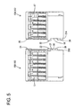
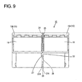
- a retainer insertion hole having an open upper side and such a depth as to substantially communicate with (at least part of) the respective cavities 16 preferably is formed at (preferably a rear side of) the lateral (upper) surface of each block 15A, 15B with respect to the connecting direction CD of the female housing 10, and a retainer 18 preferably is at least partly inserted into this retainer insertion hole 17 to (preferably doubly) lock the female terminal fittings 14 preferably in cooperation with the locking portions 31 (see FIGS. 5 and 9).
- At least one undercut or dovetail groove 19 (corresponding to a preferred engaging portion) preferably retracted rightward in FIG. 1 and/or extending substantially in a mating direction MD or in vertical direction (direction at an angle different from 0° or 180°, preferably substantially normal to the connecting direction CD of the female housing 10) is formed at (preferably a front side of) the lateral (left) surface of the first block 15A.
- first block 15A In the lateral (left) surface (boundary surface to the second block 15B) of the first block 15A are formed one or more, preferably two undercut or dovetail-groove side tab-shaped terminal insertion passages 20 extending substantially backward from the front surface of the first block 15A substantially along the connecting direction CD of the female housing 10 and/or arranged one above the other. These dovetail-groove side tab-shaped terminal insertion passages 20 extend to substantially communicate with the dovetail groove 19.
- the male tabs 13 are at least partly insertable into the dovetail-groove side tab-shaped terminal insertion passages 20, and one or more tapered surfaces 21A for guiding the male tabs 13 are formed at or near the front opening(s) of the dovetail-groove side tab-shaped terminal insertion passage(s) 20.
- a rear wall portion 22 located substantially behind preferably is cut off from the bottom end of the first block 15A to a specified (predetermined or predeterminable) height position, and comes substantially into contact with a contact wall portion 23 of the second block 15B to be described later.
- At least one engaging-projection receiving portion 25 (corresponding to a preferred positioning portion) engageable with at least one engaging projection 24 (corresponding to a preferred positioning portion) to be described later preferably is so formed at a position of the lateral (left) surface of the first block 15A near the rear end and the bottom end as to be retracted rightward in FIG. 1.
- At least one tapered surface 26A inclined outward toward the top is formed in the lateral (left) surface of the first block 15A substantially below the engaging-projection receiving portion 25 from the bottom edge, so that the engaging projection 24 can easily move onto.
- At least one rib 27 (corresponding to a preferred interacting portion) projecting laterally or towards the neighboring block 15A (rightward in FIG. 1) and engageable with the dovetail groove 19 is formed at a position of the front side of the lateral (right) surface of the second block 15B substantially corresponding to the aforementioned dovetail groove 19 (see FIG. 4).
- One or more rib side tab-shaped terminal insertion passages 28 extending substantially in forward and backward directions (or substantially along the connecting direction CD) are formed preferably one substantially above the other in the rib 27, and the respective one or more male tabs 13 are at least partly insertable into these rib side tab-shaped terminal insertion passages 28.
- One or more back walls 30 of the rib side tab-shaped terminal insertion passages 28 preferably are so set as not to interfere with the leading ends of the male tabs 13 when the two housings 10, 11 are properly connected with the two blocks 15A, 15B united or integrally connected at substantially proper positions.
- the contact wall portion 23 projecting substantially backward is formed at the bottom end of the rib 27, and a downward displacement (or displacement substantially along the mating direction MD) of the first block 15A is prevented by the contact of the bottom end surface of the aforementioned rear wall portion 22 of the first block 15A with the upper surface of this contact wall portion 23 from above.
- One or more tapered surfaces 21B for substantially guiding the male tabs 13 are formed at positions located at preferably the front edge of the lateral (right) surface (boundary surface to the first block 15A) of the second block 15B and/or substantially corresponding to the dovetail-groove side tab-shaped terminal insertion passages 20 of the first block 15A.
- the engaging projection 24 projecting laterally is formed at a position located near the rear end of the right surface of the second block 15B and/or substantially corresponding to the engaging-projection receiving portion 25 of the first block 15A.
- At least one tapered surface 26B preferably is formed on or near the upper surface of the engaging projection 24, so that the engaging projection 24 can easily move over the wall surface below the engaging-projection receiving portion 25.
- the bottom end surface of the engaging projection 24 preferably is formed to be perpendicular to the right surface of the second block 15B, and an upward displacement (or displacement substantially along the mating direction MD) of the first block 15A is prevented by the contact of the bottom end surface of this engaging projection 24 with the bottom end surface of the engaging-projection receiving portion 25 from above.
- the first block 15A and the second block 15B can be united substantially along the mating direction MD by sliding the first block 15A relative to the second block 15B from above to at least partly fit the rib(s) 27 into the dovetail groove(s) 19.
- the bottom surface of the rear wall portion 22 of the first block 15A is substantially in contact with the upper surface of the contact wall portion 23 of the second block 15B from above to prevent a downward displacement of the first block 15A
- the bottom end surface of the engaging projection 24 of the second block 15B is in contact with the bottom surface of the engaging-projection receiving portion 25 of the first block 15A from above to prevent an upward displacement of the first block 15A.
- first and second blocks 15A, 15B are positioned with respect to vertical direction (or substantially along the mating direction MD). Further, displacements of the first and second blocks 15A, 15B along forward and backward directions (or connecting direction CD) and/or width direction WD are prevented by the engagement of the rib(s) 27 of the second block 15B with the intersecting (substantially vertically extending) dovetail groove(s) 19 formed in the first block 15A.
- the mating direction MD is arranged at an angle different from 0° or 180°, preferably substantially normal to the forward and backward directions (or connecting direction CD) and/or the width direction WD.
- the dovetail-groove side tab-shaped terminal insertion passage(s) 20 formed in the first block 15A and the rib side tab-shaped terminal insertion passage(s) 28 formed in the second block 15B communicate with each other, whereby one or more tab-shaped terminal insertion passages 29 extending substantially backward from the connecting surface of the female housing 10 with the male housing 11 substantially along the boundary surfaces of the first and second blocks 15A, 15B are formed substantially up to the dovetail groove 19 and/or the rib 27.
- the dovetail-groove side tab-shaped terminal insertion passage(s) 20 and the rib side tab-shaped terminal insertion passage(s) 28 preferably is/are substantially aligned by the engagement of the aforementioned engaging projection 24 and engaging-projection receiving portion 25.
- the cavities 16 formed in the first and second blocks 15A, 15B are arrayed in one or more rows substantially along width direction WD with the first and second blocks 15A, 15B united at the substantially proper positions.
- the tab-shaped terminal insertion passages 29 substantially are vertically aligned with each other and/or aligned with the row(s) of the cavities at the one or more , preferably the two (upper and lower) stages along width direction WD.
- the male housing 11 is connectable with the preferably divided-type female housing 10 formed by uniting the first and second blocks 15A, 15B and also connectable with a unitary-type female housing 40.
- FIG. 12 shows the unitary-type female housing 40 for comparison with the divided-type female housing 10 according to this embodiment.
- the unitary-type female housing 40 is made e.g. of synthetic resin, and one or more, preferably a plurality of cavities 16 for at least partly accommodating the one or more respective female terminal fittings 14 are formed to penetrate the female housing 40 substantially in forward and backward directions while preferably being arranged substantially side by side along width direction WD and/or vertical direction at one or more stages (at two stages in the shown example).
- the male tabs 13 are at least partly inserted in (preferably all) the cavities 16.
- the tab-shaped terminal insertion passages 29 are formed at the positions substantially corresponding to specified (predetermined or predeterminable) cavities (e.g. the seventh cavity at the upper stage from left in FIG. 1 and the eighth cavity at the lower stage from left in FIG. 1) in the unitary-type female housing 40.
- the first block 15A is placed slantedly or inclined with respect to (e.g. obliquely upward to right of) the second block 15B and is slid downward to bring the lateral (left) surface of the first block 15A and the corresponding lateral (right) surface of the second block 15B substantially into sliding contact.
- the rib 27 of the second block 15B is at least partly fitted into the dovetail groove 19 of the first block 15A.
- first block 15A is further slid substantially along the mating direction MD (downward), it is displaced substantially along the mating direction MD (downward) by being guided by the dovetail groove 19 and the engaging projection 24 of the second block 15B comes substantially into contact with the bottom edge of the right surface of the first block 15A from below. Then, the engaging projection 24 and the tapered surface 26B of the second block 15B come substantially into sliding contact with the tapered surface 26A formed at the bottom edge of the left surface of the first block 15A, whereby the engaging projection 24 moves onto the left surface of the first block 15A. When the first block 15A is pushed further substantially along the mating direction MD (downward), the engaging projection 24 is at least partly fitted into the engaging-projection receiving portion 25.
- the bottom end surface of the engaging projection 24 comes substantially into contact with the bottom surface of the engaging-projection receiving portion 25 from above, thereby preventing an upward displacement of the first block 15A.
- the bottom surface of the rear wall portion 22 of the first block 15A comes substantially into contact with the upper surface of the contact wall portion 23 of the second block 15B from above, thereby preventing a downward displacement of the first block 15A.
- displacements of the first and second blocks 15A, 15B along forward and backward directions (or connecting direction CD) and/or width direction WD are prevented by fitting the rib 27 into the dovetail groove 19 extending substantially along the mating direction MD (or vertical direction). In this way, the first and second blocks 15A, 15B are positioned and assembled to form the divided-type female housing 10.
- the male tabs 13 corresponding to the area where the dovetail groove 19 and the rib 27 are formed may strike against the front surface of the female housing 10, making it impossible to connect the two housings 10, 11.
- the male tabs 13 may not be formed at positions corresponding to the area where the dovetail groove 19 and the rib 27 are formed.
- the male housing 11 is exclusively used for the divided-type female housing 10 and preferably cannot be commonly used for the unitary-type female housing 40.
- the one or more tab-shaped terminal insertion passages 29 preferably are so formed in the boundary surfaces of the first and second blocks 15A, 15B as to extend substantially backward up to the dovetail groove 19 and the rib 27 from the connecting surface with the male housing 11.
- the male tabs 13 can be formed at the positions corresponding to the area of the divided-type female housing 10 where the dovetail groove 19 and the rib 27 are formed, wherefore the male housing 11 can be commonly used for both the unitary-type female housing 40 and the divided-type female housing 10 avoiding particularly a risk of damaging the male tabs 13.
- the male tabs 13 are guided by the tapered surfaces 21A, 21B formed at the opening edges of the tab-shaped terminal insertion passages 29.
- the dovetail-groove side tab-shaped terminal insertion passages 20 and the rib side tab-shaped terminal insertion passages 28 preferably are not aligned, with the result that parts of the inner walls of the tab-shaped terminal insertion passages 29 may project inward. If an attempt is made to connect the two housings 10, 11 in such a case, the male tabs 13 may interfere with the inward projecting parts of the inner walls of the tab-shaped terminal insertion passages 29.
- the engaging-projection receiving portion 25 is formed in the first block 15A and the engaging projection 24 is formed on the second block 15B in this embodiment.
- the dovetail-groove side tab-shaped terminal insertion passages 20 and the rib side tab-shaped terminal insertion passages 28 can be substantially aligned when the respective blocks 15A, 15B are united or integrally connected. This can prevent the interference of the male tabs 13 with the inner walls of the tab-shaped terminal insertion passages 29.
- the respective blocks 15A, 15B preferably are not displaced relative to each other along the connecting direction CD of the female housing 10 while being united with each other since the dovetail groove 19 is formed to extend substantially in the mating direction MD at an angle different from 0° or 180°, preferably substantially normal to the connecting direction CD of the female housing 10.
- a female housing 10 is divided into at least a first block 15A and a second block 15B, which can be united or integrally connected by at least partly fitting at least one rib 27 of the second block 15B into at least one respective dovetail or undercut groove 19 of the first block 15A.
- one or more tab-shaped terminal insertion passages 29 are formed substantially up to the dovetail groove 19 and the rib 27 in the female housing 10.
- a male housing 11 can be commonly used for a unitary-type female housing 40 and the divided-type female housing 10.
Landscapes
- Connector Housings Or Holding Contact Members (AREA)
Applications Claiming Priority (1)
| Application Number | Priority Date | Filing Date | Title |
|---|---|---|---|
| JP2006024672A JP4770491B2 (ja) | 2006-02-01 | 2006-02-01 | コネクタ |
Publications (2)
| Publication Number | Publication Date |
|---|---|
| EP1816709A1 true EP1816709A1 (de) | 2007-08-08 |
| EP1816709B1 EP1816709B1 (de) | 2010-12-15 |
Family
ID=37930354
Family Applications (1)
| Application Number | Title | Priority Date | Filing Date |
|---|---|---|---|
| EP07001755A Ceased EP1816709B1 (de) | 2006-02-01 | 2007-01-26 | Verbinder, Verbindungseinrichtung und Montageverfahren dafür |
Country Status (5)
| Country | Link |
|---|---|
| US (1) | US7404744B2 (de) |
| EP (1) | EP1816709B1 (de) |
| JP (1) | JP4770491B2 (de) |
| CN (1) | CN101034774B (de) |
| DE (1) | DE602007011126D1 (de) |
Cited By (1)
| Publication number | Priority date | Publication date | Assignee | Title |
|---|---|---|---|---|
| EP3467954A4 (de) * | 2016-05-24 | 2020-01-22 | Nippon Tanshi Co., Ltd. | Verbinderstruktur |
Families Citing this family (12)
| Publication number | Priority date | Publication date | Assignee | Title |
|---|---|---|---|---|
| CN201207448Y (zh) * | 2008-04-21 | 2009-03-11 | 富士康(昆山)电脑接插件有限公司 | 电连接器 |
| JP5233962B2 (ja) * | 2009-11-10 | 2013-07-10 | 住友電装株式会社 | ジョイントコネクタ及びワイヤハーネス |
| JP5091983B2 (ja) * | 2010-06-16 | 2012-12-05 | 矢崎総業株式会社 | レバー嵌合式コネクタ |
| CN102148461B (zh) * | 2010-11-30 | 2013-01-02 | 天津市柯文制模注塑有限公司 | 一种汽车线束连接器 |
| JP6112423B2 (ja) * | 2014-04-01 | 2017-04-12 | 住友電装株式会社 | コネクタ、及びワイヤハーネスに対するコネクタの固定構造 |
| CN204516961U (zh) * | 2015-04-07 | 2015-07-29 | 泰科电子(上海)有限公司 | 电连接器 |
| CN108616019B (zh) * | 2016-12-12 | 2019-11-01 | 富士康(昆山)电脑接插件有限公司 | 电连接器 |
| FR3064826B1 (fr) * | 2017-03-29 | 2020-10-09 | Tyco Electronics France Sas | Ensemble de support pour broches de contact a ajustement par pression |
| WO2018211560A1 (ja) * | 2017-05-15 | 2018-11-22 | 住友電装株式会社 | コネクタ |
| CN207052834U (zh) * | 2017-06-05 | 2018-02-27 | 泰科电子(上海)有限公司 | 用于电连接器的壳体和电连接器 |
| CN110356676A (zh) * | 2018-04-09 | 2019-10-22 | 西蒙公司 | 组合式盒 |
| US11942771B2 (en) * | 2021-01-13 | 2024-03-26 | Sumitomo Wiring Systems, Ltd. | Power distribution box with an engagement feature for overcoming a cantilevered force of a bend in a wire bundle |
Citations (5)
| Publication number | Priority date | Publication date | Assignee | Title |
|---|---|---|---|---|
| JPH10106670A (ja) * | 1996-09-26 | 1998-04-24 | Sumitomo Wiring Syst Ltd | 分割式コネクタ |
| DE19918378A1 (de) * | 1998-04-27 | 1999-11-04 | Yazaki Corp | Koppel-Verbinder |
| US6120332A (en) | 1995-09-26 | 2000-09-19 | The Whitaker Corporation | Apparatus for connecting an electrical connector to a complementary connector |
| US6129593A (en) * | 1996-03-12 | 2000-10-10 | Sumitomo Wiring Systems, Ltd. | Block connector |
| EP1202393A2 (de) * | 2000-10-27 | 2002-05-02 | SUMITOMO WIRING SYSTEMS, Ltd. | Elektrischer Verbinder |
Family Cites Families (10)
| Publication number | Priority date | Publication date | Assignee | Title |
|---|---|---|---|---|
| JPS5139788A (ja) * | 1974-10-01 | 1976-04-02 | Maruzen Oil Co Ltd | Parahidorokishisuchirennojugotai no seizohoho |
| JPS59110983A (ja) * | 1982-12-16 | 1984-06-27 | Mitsubishi Electric Corp | 油圧制御弁 |
| US4674812A (en) * | 1985-03-28 | 1987-06-23 | Siemens Aktiengesellschaft | Backplane wiring for electrical printed circuit cards |
| JPS63211584A (ja) * | 1985-11-22 | 1988-09-02 | コンポ−ネンツ、コ−ポレ−シヨン | モジユ−ル電気コネクタ構造 |
| JP3625109B2 (ja) * | 1996-08-30 | 2005-03-02 | 矢崎総業株式会社 | コネクタの結合構造 |
| JP3330507B2 (ja) * | 1997-03-11 | 2002-09-30 | 矢崎総業株式会社 | 合体コネクタ |
| JPH10255896A (ja) * | 1997-03-13 | 1998-09-25 | Yazaki Corp | 合体コネクタ |
| US6179653B1 (en) * | 2000-03-23 | 2001-01-30 | Simula Co. Ltd. | Stacking computer connector |
| JP2004319140A (ja) * | 2003-04-11 | 2004-11-11 | Sumitomo Wiring Syst Ltd | コネクタ |
| US7316582B2 (en) * | 2004-08-03 | 2008-01-08 | Wonten Technology Co., Ltd. | Piled-up audio-source socket |
-
2006
- 2006-02-01 JP JP2006024672A patent/JP4770491B2/ja not_active Expired - Fee Related
-
2007
- 2007-01-26 DE DE602007011126T patent/DE602007011126D1/de active Active
- 2007-01-26 EP EP07001755A patent/EP1816709B1/de not_active Ceased
- 2007-01-30 US US11/699,968 patent/US7404744B2/en active Active
- 2007-01-31 CN CN2007100061113A patent/CN101034774B/zh not_active Expired - Fee Related
Patent Citations (5)
| Publication number | Priority date | Publication date | Assignee | Title |
|---|---|---|---|---|
| US6120332A (en) | 1995-09-26 | 2000-09-19 | The Whitaker Corporation | Apparatus for connecting an electrical connector to a complementary connector |
| US6129593A (en) * | 1996-03-12 | 2000-10-10 | Sumitomo Wiring Systems, Ltd. | Block connector |
| JPH10106670A (ja) * | 1996-09-26 | 1998-04-24 | Sumitomo Wiring Syst Ltd | 分割式コネクタ |
| DE19918378A1 (de) * | 1998-04-27 | 1999-11-04 | Yazaki Corp | Koppel-Verbinder |
| EP1202393A2 (de) * | 2000-10-27 | 2002-05-02 | SUMITOMO WIRING SYSTEMS, Ltd. | Elektrischer Verbinder |
Cited By (2)
| Publication number | Priority date | Publication date | Assignee | Title |
|---|---|---|---|---|
| EP3467954A4 (de) * | 2016-05-24 | 2020-01-22 | Nippon Tanshi Co., Ltd. | Verbinderstruktur |
| US10673173B2 (en) | 2016-05-24 | 2020-06-02 | Nippon Tanshi Co., Ltd. | Connector structure |
Also Published As
| Publication number | Publication date |
|---|---|
| DE602007011126D1 (de) | 2011-01-27 |
| JP2007207565A (ja) | 2007-08-16 |
| CN101034774A (zh) | 2007-09-12 |
| US7404744B2 (en) | 2008-07-29 |
| US20070178765A1 (en) | 2007-08-02 |
| EP1816709B1 (de) | 2010-12-15 |
| JP4770491B2 (ja) | 2011-09-14 |
| CN101034774B (zh) | 2010-12-08 |
Similar Documents
| Publication | Publication Date | Title |
|---|---|---|
| EP1816709B1 (de) | Verbinder, Verbindungseinrichtung und Montageverfahren dafür | |
| EP1923962B1 (de) | Stecker und Vormontageverfahren dafür | |
| EP2164137B1 (de) | Steckverbinder, Anschlussklemme, Kabelbaum mit einem Steckverbinder und Verfahren zu seinem Zusammenbau | |
| US10340621B2 (en) | Connector with moving plate having partition between terminals to prevent short-circuit | |
| EP2495821A1 (de) | Steckverbinder und Montageverfahren dafür | |
| EP1990869B1 (de) | Steckverbinder und Montageverfahren dafür | |
| EP2530787A2 (de) | Steckverbinder und Montageverfahren dafür | |
| EP1294057B1 (de) | Anschlusskontakt, damit ausgestatteter Steckverbinder und Herstellungsverfahren des Anschlusskontaktes | |
| US6769934B2 (en) | Connector and an unlocking jig therefor | |
| EP1524730A1 (de) | Elektrischer Verbinder | |
| EP1524727A1 (de) | Elektrischer Verbinder | |
| EP2453530B1 (de) | Leiterplattensteckverbinder, Verfahren zu dessen Zusammenfügen und Verfahren zu dessen Anbringen an einer Leiterplatte | |
| JP2008305578A (ja) | コネクタ | |
| EP0963009A1 (de) | Eine Vorrichtung zur Verhinderung einer fehlerhaften Zusammensetzung eines Verbindergehäuses mit einem Deckel und einen Verbinder mit einer solchen Vorrichtung | |
| EP1557908A2 (de) | Ein verbinder | |
| EP1641083A2 (de) | vERBINDER UND VERBINDERANORDNUNG | |
| JP2008198528A (ja) | 基板用コネクタ | |
| EP1089390B1 (de) | Anschlusselement, Verbinder und Verfahren zu dessen Zusammenbau | |
| EP2325950B1 (de) | Steckverbinder | |
| US7001206B2 (en) | Connector and a connector assembly | |
| EP1801926B1 (de) | Verbinder und Verbinderanordnung | |
| CN101345369A (zh) | 电连接器组装体、阳型连接器 | |
| EP1746689B1 (de) | Modularer Verbinder und Verfahren zu seiner Zusammenstellung | |
| US7001224B2 (en) | Connector with retainer for locking terminal fitings | |
| JP4668955B2 (ja) | コネクタハウジング |
Legal Events
| Date | Code | Title | Description |
|---|---|---|---|
| PUAI | Public reference made under article 153(3) epc to a published international application that has entered the european phase |
Free format text: ORIGINAL CODE: 0009012 |
|
| 17P | Request for examination filed |
Effective date: 20070201 |
|
| AK | Designated contracting states |
Kind code of ref document: A1 Designated state(s): AT BE BG CH CY CZ DE DK EE ES FI FR GB GR HU IE IS IT LI LT LU LV MC NL PL PT RO SE SI SK TR |
|
| AX | Request for extension of the european patent |
Extension state: AL BA HR MK YU |
|
| AKX | Designation fees paid |
Designated state(s): DE FR |
|
| GRAP | Despatch of communication of intention to grant a patent |
Free format text: ORIGINAL CODE: EPIDOSNIGR1 |
|
| GRAS | Grant fee paid |
Free format text: ORIGINAL CODE: EPIDOSNIGR3 |
|
| GRAA | (expected) grant |
Free format text: ORIGINAL CODE: 0009210 |
|
| AK | Designated contracting states |
Kind code of ref document: B1 Designated state(s): DE FR |
|
| REF | Corresponds to: |
Ref document number: 602007011126 Country of ref document: DE Date of ref document: 20110127 Kind code of ref document: P |
|
| PLBE | No opposition filed within time limit |
Free format text: ORIGINAL CODE: 0009261 |
|
| STAA | Information on the status of an ep patent application or granted ep patent |
Free format text: STATUS: NO OPPOSITION FILED WITHIN TIME LIMIT |
|
| 26N | No opposition filed |
Effective date: 20110916 |
|
| REG | Reference to a national code |
Ref country code: DE Ref legal event code: R097 Ref document number: 602007011126 Country of ref document: DE Effective date: 20110916 |
|
| REG | Reference to a national code |
Ref country code: FR Ref legal event code: PLFP Year of fee payment: 10 |
|
| REG | Reference to a national code |
Ref country code: FR Ref legal event code: PLFP Year of fee payment: 11 |
|
| REG | Reference to a national code |
Ref country code: DE Ref legal event code: R084 Ref document number: 602007011126 Country of ref document: DE |
|
| REG | Reference to a national code |
Ref country code: FR Ref legal event code: PLFP Year of fee payment: 12 |
|
| PGFP | Annual fee paid to national office [announced via postgrant information from national office to epo] |
Ref country code: DE Payment date: 20211130 Year of fee payment: 16 |
|
| P01 | Opt-out of the competence of the unified patent court (upc) registered |
Effective date: 20230517 |
|
| REG | Reference to a national code |
Ref country code: DE Ref legal event code: R119 Ref document number: 602007011126 Country of ref document: DE |
|
| PG25 | Lapsed in a contracting state [announced via postgrant information from national office to epo] |
Ref country code: DE Free format text: LAPSE BECAUSE OF NON-PAYMENT OF DUE FEES Effective date: 20230801 |
|
| PGFP | Annual fee paid to national office [announced via postgrant information from national office to epo] |
Ref country code: FR Payment date: 20231212 Year of fee payment: 18 |
|
| PG25 | Lapsed in a contracting state [announced via postgrant information from national office to epo] |
Ref country code: FR Free format text: LAPSE BECAUSE OF NON-PAYMENT OF DUE FEES Effective date: 20250131 |