EP1817761B1 - Appareil et methode pour la detection automatique d`objets - Google Patents
Appareil et methode pour la detection automatique d`objets Download PDFInfo
- Publication number
- EP1817761B1 EP1817761B1 EP05810778A EP05810778A EP1817761B1 EP 1817761 B1 EP1817761 B1 EP 1817761B1 EP 05810778 A EP05810778 A EP 05810778A EP 05810778 A EP05810778 A EP 05810778A EP 1817761 B1 EP1817761 B1 EP 1817761B1
- Authority
- EP
- European Patent Office
- Prior art keywords
- vehicle
- image
- edge
- road
- velocity
- Prior art date
- Legal status (The legal status is an assumption and is not a legal conclusion. Google has not performed a legal analysis and makes no representation as to the accuracy of the status listed.)
- Ceased
Links
Images




Classifications
-
- G—PHYSICS
- G06—COMPUTING OR CALCULATING; COUNTING
- G06V—IMAGE OR VIDEO RECOGNITION OR UNDERSTANDING
- G06V40/00—Recognition of biometric, human-related or animal-related patterns in image or video data
- G06V40/10—Human or animal bodies, e.g. vehicle occupants or pedestrians; Body parts, e.g. hands
-
- G—PHYSICS
- G06—COMPUTING OR CALCULATING; COUNTING
- G06T—IMAGE DATA PROCESSING OR GENERATION, IN GENERAL
- G06T7/00—Image analysis
- G06T7/10—Segmentation; Edge detection
- G06T7/12—Edge-based segmentation
-
- G—PHYSICS
- G06—COMPUTING OR CALCULATING; COUNTING
- G06T—IMAGE DATA PROCESSING OR GENERATION, IN GENERAL
- G06T7/00—Image analysis
- G06T7/20—Analysis of motion
- G06T7/215—Motion-based segmentation
-
- G—PHYSICS
- G06—COMPUTING OR CALCULATING; COUNTING
- G06V—IMAGE OR VIDEO RECOGNITION OR UNDERSTANDING
- G06V20/00—Scenes; Scene-specific elements
- G06V20/50—Context or environment of the image
- G06V20/56—Context or environment of the image exterior to a vehicle by using sensors mounted on the vehicle
- G06V20/58—Recognition of moving objects or obstacles, e.g. vehicles or pedestrians; Recognition of traffic objects, e.g. traffic signs, traffic lights or roads
-
- G—PHYSICS
- G06—COMPUTING OR CALCULATING; COUNTING
- G06V—IMAGE OR VIDEO RECOGNITION OR UNDERSTANDING
- G06V20/00—Scenes; Scene-specific elements
- G06V20/50—Context or environment of the image
- G06V20/56—Context or environment of the image exterior to a vehicle by using sensors mounted on the vehicle
- G06V20/588—Recognition of the road, e.g. of lane markings; Recognition of the vehicle driving pattern in relation to the road
-
- G—PHYSICS
- G06—COMPUTING OR CALCULATING; COUNTING
- G06T—IMAGE DATA PROCESSING OR GENERATION, IN GENERAL
- G06T2207/00—Indexing scheme for image analysis or image enhancement
- G06T2207/10—Image acquisition modality
- G06T2207/10016—Video; Image sequence
-
- G—PHYSICS
- G06—COMPUTING OR CALCULATING; COUNTING
- G06T—IMAGE DATA PROCESSING OR GENERATION, IN GENERAL
- G06T2207/00—Indexing scheme for image analysis or image enhancement
- G06T2207/30—Subject of image; Context of image processing
- G06T2207/30248—Vehicle exterior or interior
- G06T2207/30252—Vehicle exterior; Vicinity of vehicle
- G06T2207/30256—Lane; Road marking
Definitions
- the present invention pertains to the technical field of object detection, and in particular to techniques for detecting any moving object in front of a vehicle.
- Japanese Kokai Patent Application No. Hei 10[1998]-214326 discloses an automatic guidance system that uses Hough transformation to detect road edges from images in front of a vehicle.
- a string of detected edges is arranged side-by-side on a straight line and is subjected to Hough transformation to detect the road edges.
- Hough transformation as the points that form the road edges are detected, curves are drawn in the parameter space, and the accumulated values of the points on the curves have to be added. This processing may be performed for all of the points that form the road edges, in which case the processing load is heavy. It would be desirable to provide an less computationally-intensive technique to detect road edges or other boundary lines in the path of a vehicle.
- U.S. Patent No. 6,466,684 teaches an environment monitoring system using optical flow where a monitoring region is set in one's own vehicle lane or an adjacent lane on the basis of the white lines.
- An image is divided into a plurality of small regions, and an edge is extracted as a candidate for the white lines in each small region using a virtual FOE.
- a white line is determined from the extracted edge.
- the white line segments are extended to acquire a coordinate of a crossing point thereof and that of the virtual FOE is stored for each the small regions.
- the virtual FOE is used to extract the edge for each of the small regions of an image newly picked-up in order to detect the optical flow.
- an apparatus for detecting objects in one or more images captured by an image pickup device mounted on a vehicle.
- the apparatus includes a memory on which is stored pixels of at least one image captured by the image pickup device; and a controller operatively coupled to the memory.
- the controller is adapted to compute velocity information for each pixel in the image; extract those pixels having a velocity component based on the velocity information; detect a pair of oblique lines composed of those extracted pixels having a velocity component, and generate a signal indicative of the road edge in the image based on the oblique lines.
- a method for detecting objects in an image captured from in front of a vehicle.
- the method includes processing the image to compute velocity information for each pixel in the image; extracting pixels having a velocity component on the basis of the velocity information of the pixels of the images computed by the velocity information computing means; detecting a pair of oblique lines made of pixels having a velocity component and extracted by the pixel extracting means; and detecting the boundary line on the road present in the image in front of the vehicle on the basis of the oblique line detected by the oblique line detecting means.
- Figure 1 is a block diagram of an object detection device in accordance with a first embodiment of the invention
- Figure 2A is a side elevation of a vehicle in which the device of Figure 1 has been installed, including a camera;
- Figure 2B is a top plan view of the vehicle shown in Figure 2A ;
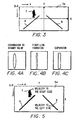
- Figure 3 is a diagram of an image captured by the camera shown in Figure 2A ;
- Figure 4A shows an image in which an edge in a stored image has been extracted
- Figure 4B shows the image of Figure 4A after it has been subjected to a line-thinning process
- Figure 4C shows the image of Figure 4B after it has been expanded to a fixed width
- Figure 5 is a diagram of an image captured by the camera shown in Figure 2A , including a depiction of a velocity image;
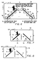
- Figure 6 is a diagram of an image captured by the camera shown in Figure 2A , including a road edge detecting region that is established in the velocity image;
- Figure 7 is a diagram of the image shown in Figure 6 , illustrating the extraction of the pixels having a velocity component towards the center of the two dimensional road model;
- Figure 8 is a diagram of the image shown in Figure 6 , illustrating the detection of an object field containing a pedestrian moving towards center of the two dimensional road model, by grouping the pixels having the same velocity component towards center in the two dimensional road model in the velocity image;
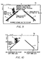
- Figure 9 is a diagram of the image shown in Figure 6 , illustrating the direction of movement of the oblique lines in the velocity image when pitching takes place;
- Figure 10 is a diagram of the image shown in Figure 6 , illustrating the transformation of a two dimensional road model into a three dimensional road model;
- Figure 11 is a diagram of the relative positional relationships among the vehicle shown in Figure 2A , the road edges and the object detected in real space;
- Figure 12A is a flow chart of the operation of the object detection device shown in Figure 1 ;
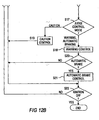
- Figure 12B is a continuation of the flow chart shown in Figure 12A ;
- Figure 13 is a diagram of an image captured by the camera shown in Figure 2A , in accordance with a second embodiment of the invention.
- Figure 14 is a diagram of the image shown in Figure 13 , illustrating a depiction of the velocity component
- Figure 15 is a diagram of the image shown in Figure 13 , illustrating the formation of regions for detecting boundary lines in the velocity image;
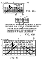
- Figure 16A is a diagram of the image shown in Figure 13 , illustrating the detection of candidates for oblique lines and the application of a spatial filter;
- Figure 16B is a chart showing the identification of an oblique line candidate in accordance with the second embodiment of the invention.
- Figure 17 is a diagram of the image shown in Figure 13 , illustrating the detection of boundary lines on the road;
- Figure 18A is the flow chart illustrating the processing of object detecting device in accordance with the second embodiment of the invention.
- Figure 18B is a continuation of the flow chart of Figure 18A ;
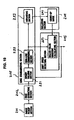
- Figure 19 is a block diagram showing a detailed structure an edge-width standardizing section
- Figure 20 is a view illustrating thin-line condensing operation and expanding operation by the edge-width standardizing section shown in Figure 19 ;
- Figure 21 is a view illustrating a count up operation of a balloting module.
- FIG. 1 is a block diagram illustrating an object detection device in accordance with a first embodiment of the present invention.
- Object detecting device 100 is mounted on the vehicle. It has the following parts: camera 101, image memory 102 that stores the images taken with the camera 101, controller 103 that executes image processing of the images taken with camera 101 and stored in image memory 102, counter memory 104 that stores the count value of the pixel counter to be explained later, speaker 105 that outputs sounds, automatic braking device 106 that controls the vehicle brakes, and vehicle speed sensor 107 that detects the speed of the vehicle.
- Camera 101 is a high speed camera having CCD, CMOS or other image pickup elements, and it can take consecutive images of objects from ahead of the vehicle.
- the image frames are output to image memory 102.
- the camera 101 is arranged on the upper front portion of the vehicle, as shown in Figures 2A and 2B . Its sight of view axial direction Z is in front of the vehicle. It is set such that horizontal axis X of the imaging area is parallel to the ground surface, and vertical axis Y of the imaging area is perpendicular to the ground surface.
- the images taken by camera 101 are consecutively output and stored in image memory 102.
- Figure 3 is a diagram illustrating an example of the image taken with camera 101.
- Image 3a is taken with camera 101 in an xy coordinate system (camera coordinates) with the origin at the upper left portion of the image, and with the X axis defined from left to right and Y axis defined from upper to lower.
- image 3a includes road edges A and B formed as edge bumps, white lines or guard rails or the like positioned on the left/right sides of the road, and pedestrian C present in front of the vehicle.
- Controller 103 processes image 3a stored in image memory 102, as will be explained later, detects the object present ahead of the vehicle, and when there is a danger of collision of the vehicle with the object present ahead of the vehicle, it outputs an alarm (alarm sound) to the driver by means of speaker 105, and automatic braking device 106 is controlled to automatically brake or stop the vehicle.
- an alarm alarm sound
- automatic braking device 106 is controlled to automatically brake or stop the vehicle.
- the image taken with camera 101 is read from image memory 102, and the edges of the object present in image 3a are extracted by means of transformation to binary values with a prescribed threshold. For each extracted edge in the image, finer line processing is performed to determine the center of the edge correctly. The edge in fine line form is then expanded so that the edge has a prescribed width, such as that corresponding to 3 pixels. By normalizing the extracted edge, it is possible to obtain an edge image with a uniform width of the edges.
- Figures 4A -4C are diagrams illustrating an example of the processing performed to normalize the extracted edges to obtain an edge image.
- the obtained edge in binary form is subjected to finer line processing to obtain an edge in a finer line form, as shown in Figure 4B .
- the edge in finer line form is then expanded to have a constant edge width as shown in Figure 4C .
- the count value of the pixel counter corresponding to the pixels with an edge present in them in the current edge image is then refreshed in the pixel counter stored in counter memory 104.
- the pixel counter is a counter corresponding to the pixels of the edge image; the count value of the pixel counter corresponding to a pixel where an edge is present is incremented by 1, and the count value of the pixel counter corresponding to a pixel where the edge is absent is initialized to 0.
- the refreshing processing of the count value is carried out for each of the frames taken consecutively with camera 101. As a result, the pixels with a longer edge presence time have a larger count value, and the pixels with a shorter edge presence time have a smaller count value.
- the difference in count values of the pixel counter for pixels adjacent to each other in the lateral direction is taken so that the difference in edge presence time is computed at each pixel, and the time needed to move the edge by 1 pixel is obtained. Then, obtaining the reciprocal of this value enables computing the velocity in the lateral direction in the image space for each pixel.
- the velocity in the lateral direction in the image space at each pixel corresponds to the movement velocity in the lateral direction of the edge contained in each pixel.
- it is possible to compute the velocity component of the edge in each pixel of the image that is, the movement direction and movement velocity of the edge.
- a velocity image is formed, with the velocity component of the object present in image 3a computed in the processing represented by the prescribed grade value.
- the pixels for which the velocity has been detected are represented by round dots, with higher movement velocities being represented by larger dots.
- the velocity towards the right side is represented by solid dots, while the velocity towards the left side is represented by circles. That is, as shown in Figure 5 , a velocity from road edge B on the right hand side of the road to the left hand side of the image is detected, and the velocity to the right hand side of the image is detected from road edge A on the left hand side of the road and from pedestrian C. Also, it is possible to judge from the size of the dots that the movement velocity detected for pedestrian C is higher than that detected for road edges A and B.
- a region for detecting the boundary line is then established for detecting the road edge or other boundary line on the road on computed velocity image 5a.
- the position where the road edge is present as the boundary line on the road on velocity image 5a is predicted, and a region with a prescribed size is set at that position.
- regions 6a 6h for detecting the boundary line are symmetrically arranged left/right so that the road edges present in velocity image 5a can be detected.
- a judgment is then made as to whether oblique lines having a velocity component exist in the regions 6a 6h for detecting the boundary line. That is, a judgment is then made as to whether pixels having a velocity component are obliquely arranged side by side in the regions 6a 6h for detecting the boundary line.
- the start point and the end point, etc. are extracted from the oblique lines, detected as road edges in the regions for detecting the boundary line, as the representative points.
- representative point 6i is extracted from region 6a for detecting the boundary line
- left representative point 6j is extracted from region 6e for detecting the boundary line.
- Double regression analysis is carried out on the basis of the extracted representative points, and the equation of the oblique lines in the XY coordinate system is derived.
- the two dimensional road model represented by Equation (1) that is, the imaged road model, is obtained.
- x a ⁇ 1 ⁇ y 2 + b ⁇ 1 ⁇ y + c ⁇ 1
- center 7a of the two dimensional road model corresponding to the predicted movement path of the vehicle is computed.
- pixels having a velocity component toward center 7a of the two dimensional road model are extracted.
- pixels having the same velocity component are grouped and are detected as an individual object.
- a region in the velocity image covering a prescribed range such as a region of 1 pixel in the longitudinal direction and 3 pixels in the lateral direction, is established as small region 7b for detecting the lower end, and the small region 7b for detecting the lower end is scanned in the velocity image from the lower side upward in the Y axis direction.
- the points where two or more pixels in small region 7b for detecting the lower end are present (distributed) with the same velocity component towards center 7a of the two dimensional road model are then detected.
- pixels positioned at the lower end of the small region 7b for detecting the lower end are detected as object lower end position 7c.
- the histogram of the velocity image is then computed from object lower end position 7c in the Y axis direction. That is, the histogram that represents the distribution of number of degrees in the X-axis direction of the pixels having the same velocity component towards center 7a of the two dimensional road model and present from object lower end position 7c in the Y axis direction is computed. Assuming the coordinate of the object lower end position 7c is y d and the degree number of the pixels having the same velocity component towards center 7a in the two dimensional road model in the Y coordinate value is V (yi) , the sum of the degree numbers in the range of the preset standard height y m of pedestrian C is computed using following Equation (2). ⁇ i - m d V y i > T ⁇ 1
- a straight line is drawn parallel to the Y axis and passing through the outermost pixel of the pixels having the same velocity component towards center 7a of the two dimensional road model and present continuously in the X axis direction.
- the region defined by the straight line parallel to the Y axis as well as object lower end position 7c and object upper end position 8a is defined as region 8b where the moving object is present (object presence range).
- the positions of road edges A, B and object presence range 8b are transformed to positions in real space.
- the pitching generated by running of the vehicle itself is taken into consideration, and it is transformed into the position in real space, as will be explained later.
- the point of change in the velocity direction of the oblique lines indicating road edges A and B in the image of the oblique lines is the pitching balance point, that is, the line of sight orientation of camera 101 is horizontal with respect to the road surface. Since the line of sight orientation of camera 101 is parallel to the road surface in velocity image 5a at the pitching balance point, as explained above, it is possible to compute the three dimensional coordinates of the representative points by means of triangulation based on the coordinates of the representative points arbitrarily set on road edges A and B, and on the camera parameters of camera 101.
- any representative points 10a and 10b are set on road edges A and B in velocity image 5a, and based on the coordinates of the representative points and the camera parameters of camera 101, the three dimensional coordinates of the representative points can be computed by means of triangulation.
- the positions of the oblique lines indicating road edges A and B are transformed to positions in real space, and the three dimensional road model, that is, the real space road model, is computed.
- the three dimensional road model that is, the real space road model
- the position of pedestrian C contained in object presence range 8b in real space is computed based on the coordinates of object central point 10c established in object presence range 8b in velocity image 5a, and on the camera parameters of camera 101. As a result, it is possible to transform the position of pedestrian C in velocity image 5a to the position in real space. Also, based on the relative positional relationships among road edges A and B and pedestrian C in real space, the distance from the vehicle itself to pedestrian C and the distance from pedestrian C to the road edge are computed. Also, the distance from the vehicle itself to pedestrian C is not the linear distance from the vehicle itself to pedestrian C. Instead, it is the distance between the position on the vehicle line corresponding to the position of pedestrian C and the position of the vehicle itself.
- the degree of collision danger between the vehicle itself and pedestrian C is judged using the following three levels 1 3.
- Level 3 When it is judged that the degree of collision danger between the vehicle and pedestrian C is the highest from the relative position relationships between the road edges and pedestrian C, the degree of collision danger is taken to be level 3. That is, as shown in Figure 11 , when pedestrian C moves inside the road edge present on the left/right sides indicated by portion 11a, that is, when the pedestrian moves inside the vehicle lines where vehicle 11d is running, the degree of collision danger between vehicle 11d and pedestrian C is judged to be at level 3.
- Level 2 When it is judged that the degree of collision danger between the vehicle and pedestrian C is not as high as level 3 yet there is still the danger of collision from the relative position relationships between the road edges and pedestrian C, the degree of collision danger is taken to be level 2.
- the degree of collision danger between vehicle 11d and pedestrian C is judged to be at level 2.
- the distance of x0 (m) is computed from the movement velocity of pedestrian C detected in the processing, the distance between vehicle 11d and pedestrian C, and the vehicle speed detected with vehicle speed sensor 107.
- Level 1 When it is judged that there is no collision danger between the vehicle and pedestrian C, the degree of collision danger for pedestrian C is taken to be level 1. In other words, when pedestrian C moves in the range indicated by portion 11c, that is, when the pedestrian moves out beyond the range of x0 (m) from the road edge, the degree of collision danger between vehicle 11d and pedestrian C is judged to be at level 1. When the judgment result of the degree of collision danger is level 1, there is no need to perform vehicle control to avoid collision, to be explained later, because there is no danger of collision between the vehicle and pedestrian C.
- Equations (3) (5) V represents the speed of the vehicle 11d
- g represents the gravitational acceleration
- z0 represents the distance 11e from the position on the vehicle line corresponding to the position of pedestrian C and the target stop line.
- vehicle control is performed to avoid collision between the vehicle and pedestrian C according to the following listed three control modes (A) (C).
- (A) Caution When the degree of collision danger is level 3, and the distance between the vehicle and pedestrian C is longer than z2 and shorter than z3, the control mode is "Caution.” When the control mode is "Caution,” a caution alarm is output from speaker 105 to alert the driver to the presence of a moving object ahead of the vehicle with which there is a danger of collision.
- (B) Warning When the degree of collision danger is level 2, or when the degree of collision danger is level 3 and the distance between the vehicle and pedestrian C is shorter than z2, the control mode is "Warning.” When the control mode is "Warning,” a warning alarm is output from speaker 105 to alert the driver to the presence of a moving object ahead of the vehicle with which there is a high danger of collision. Also, this warning alarm is different from that for "Caution" in control mode (A). For example, the volume for the warning alarm may be higher than that for the caution alarm, or, the caution alarm and warning alarm may have different rhythms.
- (C) Automatic braking When the degree of collision danger is level 3, and the distance between the vehicle and pedestrian C is shorter than z1, the control mode is "Automatic braking.” When the control mode is “Automatic braking,” automatic braking device 106 is controlled to forcibly brake the vehicle itself. That is, when there is a high danger of a collision with pedestrian C, there may be no time for the driver to perform the braking operation after hearing the caution or warning alarm. Consequently, automatic braking device 106 is in this case forcibly controlled to brake the vehicle to stop it. Also, a "warning" is issued while the control mode is "Automatic braking.”
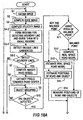
- FIGS 12A and 12B are a flow chart illustrating the processing performed by object detecting device 100 in the first embodiment.
- the ignition switch of the vehicle is turned on.
- the power of object detecting device 100 is turned on, and the operation is executed by the program started by controller 103.
- step S1 image 3a captured with camera 101 from in front of the vehicle is fetched from image memory 102.
- step S2 edge extraction processing is performed on image 3a to extract the contour of the object present in image 3a to generate an edge image.
- Process flow then proceeds to step S3.
- step S3 the edge velocity information for each pixel is computed, and the computed velocity information is transformed into a prescribed grade value to get the velocity image.
- process flow continues to step S4.
- step S4 the region for detecting the boundary line in the computed velocity image is established, and process flow continues to step S5.
- the oblique line is detected by judging whether the pixels having the velocity component in the region for detecting the boundary line are arranged side by side to form an oblique line. Then, process flow continues to step S6, and it is determined whether the oblique lines detected in the region for detecting the boundary line and forming a left/right pair have velocity components in the different directions that indicate they are the road edges. If it is determined that the detected oblique lines are not road edges, process flow continues to step S22, to be explained below. On the other hand, if it is determined that the detected oblique lines are the road edges, process flow continues to step S7.
- step S7 the two dimensional road model, that is, the imaged road model, is computed, and process flow continues to step S8.
- step S8 the pixels having a velocity component towards the center of the two dimensional road model are extracted. Then, process flow continues to step S9. Among the extracted pixels, the pixels having the same velocity component are grouped and the group is detected as an individual object. Process flow then proceeds to step S10. In step S10, grouping of the extracted pixels is completed, and a judgment is made as to whether all of the objects present in the velocity image have been detected. When it is judged that all of the objects present in the velocity image have been detected, process flow continues to step S11.
- step S11 a change in the velocity direction in the image of the oblique lines indicating the road edges is detected, and a judgment is made as to whether this is the pitching balance point.
- step S12 the positions of the oblique lines indicating the road edges are transformed to positions in real space, and the three dimensional road model is computed.
- step S 14 the relative positional relationship between the road edge and the detected object in real space, that is, the distance between the road edge and the detected object and the distance between the vehicle and the detected object, is computed.
- Process flow then proceeds to step S16, as will be explained later.
- step S13 when it is judged not to be the pitching balance point in step S11, process flow continues to step S 13.
- step S13 as explained above, based on the image pickup time interval between the velocity image at the pitching balance point and the current velocity image, the three dimensional road model is estimated, and process flow continues to step S 15.
- step S15 the relative positional relationship between the road edge and the detected object, that is, the distance between the road edge and the detected object and the distance between the vehicle and the detected object, is estimated, and process flow continues to step S16.
- step S16 based on the relative positional relationship between the road edge and the detected object, the degree of collision danger between the vehicle and the detected object is judged as one of the levels 1 3. If the degree of collision danger is judged to be level 1, no vehicle control to avoid collision is performed since there is no danger of collision between the vehicle and the detected object, and process flow continues to step S22, to be explained later. On the other hand, when it is judged that the degree of collision danger is level 2 or 3, process flow continues to step S17. In step S 17, based on the distance between the vehicle and the detected object, the mode of vehicle control for avoiding collision is assessed.
- step S19 When the control mode is the "Caution” mode, process flow continues to step S19. In this step, the caution alarm is output from speaker 105, and process flow then proceeds to step S22, to be explained later.
- step S18 In this step, a warning alarm is output from speaker 105, and process flow continues to step S20.
- step S20 a judgment is made as to whether the control mode is "Automatic brake.” If the control mode is not “Automatic brake,” process flow continues to step S22, to be explained later. On the other hand, if the control mode is "Automatic brake,” process flow continues to step S21.
- step S21 automatic braking device 106 is controlled to forcibly brake the vehicle. Then, process flow continues to step S22.
- step S22 a judgment is made as to whether the ignition switch of the vehicle itself is OFF. If it is not OFF, flow returns to step S1, and the processing is repeated. On the other hand, if it is judged that the ignition switch of the vehicle itself is OFF, the processing comes to an end.
- the region for detecting the boundary lines is established in the computed velocity image on the basis of the image captured by camera 101. If the oblique lines detected in the region for detecting the boundary lines form a pair and have velocity components in different directions, it is determined that the left/right pair of oblique lines detected in the region for detecting the boundary lines are the boundary lines on the road, that is, the road edges. As a result, the road edges contained in the image captured by camera 101 have a linear component parallel to the optical axis, so that they can definitely be picked up as oblique lines on the image. In addition, taking into consideration the fact that a moving object can easily appear within the oblique lines, it is possible to detect the road edges with high accuracy.
- the three-dimensional coordinates of the representative points can be computed by means of triangulation. Also, at the pitch balance point, the camera parameters are in approximate agreement with those in the initial state of mounting, and the precision with which distance can be measured using a triangulation scheme is high. Taking this fact into consideration, it is possible to compute three-dimensional coordinates with great accuracy.
- the degree of collision danger between the vehicle and pedestrian C can be assessed, and when the distance between the vehicle and pedestrian C is also taken into consideration, it is possible to control the vehicle to avoid a collision with pedestrian C. As a result, it is possible to make a correct judgment of the degree of danger, and it is possible to avoid a collision with pedestrian C.
- the road edges present on both sides of the vehicle and detected in the first embodiment but also various types of boundary lines on the road, such as the boundary lines of multiple lane dividing lines on a multi-lane road or the boundary lines of road and buildings, are detected.
- the block diagram shown in Figure 1 the diagrams shown in Figures 2A and 2B for illustrating an arrangement example of camera 101 on a vehicle, and the diagrams shown in Figures 4A to 4C for illustrating an example of edge normalization are the same as in the first embodiment and will not be explained again.
- Calculation of the 2-dimensional road model on the basis of the detected road edges, detection of the object field including the object facing the center of the 2 dimensional road model, the judgment of the degree of risk on the basis of the positional relationship between the object and the boundary lines on the road transformed on the 3 dimensional road model, and the vehicle control or warning operation on the basis of the result of the degree of risk judgment explained on the basis of Figures 7 11 are also carried out in the same way as described in the first embodiment and will not be explained again.
- Figure 13 shows a detailed example of an image picked by camera 101 in the second embodiment.
- image 13a is taken with the origin in the upper left corner of the image and is represented with an xy coordinate system (camera coordinates) with the x axis defined from left to right and the y axis defined from top to bottom.
- image 13a includes road edges D and E formed as lane markers, white lines or guardrails or the like positioned on the left/right sides of the road, boundary line F with the adjacent lane dividing line, and pedestrian G present in front of the vehicle.
- Velocity image 14a shown in Figure 14 is formed by carrying out the same image processing as described in the first embodiment on image 13a shown in Figure 13 .
- Multiple regions for detecting boundary lines are formed by dividing a prescribed field in the velocity image 14a.
- a prescribed field in front the vehicle for example, a distance of 20 60 m from the vehicle in real space is divided into 6 parts having prescribed height in the vertical direction (y axis direction) of the image.
- Each region divided in the vertical direction is divided at equal intervals in the horizontal direction of the image to form multiple regions 15a for detecting boundary lines in a field on the image corresponding to the prescribed field in front of the vehicle.
- Each region 15a for detecting boundary lines formed as described above is further divided into small regions having a prescribed size.
- each region 15a for detecting boundary lines is equally divided into 64 small regions.
- each region 15a for detecting boundary lines is comprised of 8x8 small regions. The candidates for the boundary lines on the road present in velocity image 14a in each divided small region are detected.
- the road edges or other boundary lines on the road are detected as oblique lines in velocity image 14a.
- the candidates for the oblique lines in each small region that is, the candidates for the boundary lines on the road can be detected by detecting the pixels having parallel velocity components in the oblique direction to form the oblique lines in each small region.
- any pixel present in each small region is taken as a target pixel. It is determined whether the target pixel constitutes an oblique line with the adjacent pixels in the oblique direction.
- the spatial filter for detecting candidates for oblique lines shown in Figure 16B is used on the target pixel. In this case, the spatial filter is applied such that the center 16a of the spatial filter matches the target pixel.
- the image of a boundary line on the road present on the right side of the vehicle is usually taken as an oblique line with a higher left end as shown by road edge E or boundary line F with the adjacent lane dividing line, and the image of a boundary line on the road present on the left side of the vehicle is usually taken as an oblique line with a higher right end as shown by road edge D.
- a spatial filter used for detecting an oblique line with a higher left end that is, the spatial filter shown in Figure 16B is applied to the target pixel present in the right half of velocity image 14a
- a spatial filter used for detecting an oblique line with a higher right end that is, a spatial filter obtained by reversing the spatial filter shown in Figure 16B in the left and right direction is applied to a target pixel present in the left side of velocity image 14a.
- the straight line formed by connecting these dot candidates is detected as a candidate for a boundary line on the road (boundary line candidate).
- the slope condition for detecting a boundary line candidate will be explained.
- the slope of a boundary line close to the vehicle is larger than the slope of a boundary line away from the vehicle.
- a boundary line close to the vehicle has a larger angle formed with the x axis than a boundary line away from the vehicle.
- the slope of road edge E present on the right side of the vehicle is smaller than the slope of boundary line F with the adjacent lane dividing line.
- a straight line formed by connecting the dot candidates detected as described above is a boundary line candidate can be determined as follows. For example, as shown in Figure 16A , when a straight line formed by connecting dot candidates is detected from small region 16b, it is determined whether straight lines formed by connecting dot candidates are detected from other small regions on the same side viewed from the vehicle and at the same height. If no straight line formed by connecting dot candidates is detected from other small regions on the same side viewed from the vehicle and at the same height as small region 16b, the straight line formed by connecting the dot candidates in small region 16b is detected as a boundary line candidate.
- a straight line formed by connecting dot candidates is detected from another region on the same side viewed from the vehicle and at the same height as small region 16b, such as, small region 16c
- the slopes of the straight lines formed by connecting the dot candidates detected in these small regions are compared to determine whether the slope of the straight line close to the vehicle is larger than the slope of the straight line away from the vehicle. If the slope of the straight line close to the vehicle is larger than the slope of the straight line away from the vehicle, both are detected as boundary line candidates that constitute part of the boundary line on the road. On the other hand, if the slope of the straight line close to the vehicle is smaller than the slope of the straight line away from the vehicle, both are excluded as boundary line candidates.
- each of the detected boundary line candidates is judged as an oblique line in the vertical direction in velocity image 14a. If continuity is confirmed for multiple boundary line candidates, the straight line formed by connecting these boundary line candidates is detected as a boundary line on the road. In this way, as shown in Figure 17 , boundary lines D, E, and F on the road can be detected from velocity image 14a.
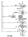
- Figures 18A and 18B are a flow chart illustrating the processing of object detecting device 100 in the second embodiment. The processing is carried out as a program started by control device 103 when the ignition switch of the vehicle is turned on and the power object for detecting device 100 is turned on.
- the same step numbers are assigned to the same processes as those that are described in the first embodiment shown in Figures 12A and 12B , and the explanation focuses on the differences of these embodiments.
- step S4-2 multiple regions 15a for detecting a boundary line are set on velocity image 14a as described above, and each region 15a for detecting a boundary line is further divided into small regions with a prescribed size. Then, process control goes to step S5-2.
- the spatial filter shown in Figure 16B is applied to the target pixel in each small region to detect the dot candidates. If 3 or more detected candidates are side by side in the oblique direction to form an oblique line in the small region and the straight line formed by connecting these dot candidates satisfies the slope condition, the straight line formed by connecting these dot candidates is detected as a boundary line candidate.
- Process control then goes to step S6 2.
- the continuity of each of the boundary line candidates detected on velocity image 14a is judged as an oblique line in the vertical direction in velocity image 14a to determine whether the straight line formed by connecting these boundary line candidates is detected as a boundary line on the road. If a boundary line on the road is detected, process control goes to step S7. If no boundary line is detected, process control goes to step S22.
- multiple regions for detecting a boundary line are formed in a prescribed field of velocity image 14a, for example, a distance of 20 60 m from the vehicle in real space.
- Candidates for the oblique lines are detected in each of the regions for detection of boundary lines, and the boundary lines on the road are detected. Consequently, in addition to the effects described in the first embodiment, in addition to the road edges present on both sides of the vehicle, various types of boundary lines on the road, such as the boundary lines of multiple lane dividing lines on a multi lane road or the boundary lines of road and buildings, can also be detected.
- the edge extracting section 202 extracts an edge of an image using a SOBEL filter for the frame image inputted from the camera 101as part of an image pickup section 201.
- the edge standardizing section 203 standardizes an edge width of the edge, extracted by the edge extracting section 202, to a given pixel number in a shift direction of the object.
- the edge-width standardizing section 203 is comprised of a binary valuing section 231 that allows the edge image, generated by the edge extracting section 202, to be valued in a binary state, a thin-line condensing section 232 that converts the edge width of the edge that is valued in the binary state by the binary valuing section 231 in a thin line to a given pixel number, and an expanding section 233 that expands the edge width of the edge, which is formed in the thin line by the thin-line condensing section 232, to a given pixel number.
- the edge standardizing section 203 configured in such a structure, if the edge image is inputted from the edge extracting section 202, the binary valuing section 231 executes binary valuing operation on the edge image. During this binary valuing operation, a pixel of a pixel area whose edge is detected is allocated to take "1" while allocating a pixel of a pixel area whose edge is not detected to be "0", upon which a binary valued image is generated as shown in a frame image (a) in Figure 20 .
- the thin-line condensing section 232 executes a thin-line condensing operation for the binary valued image that is valued by the binary valuing section 231 in a binary state.
- the thin-line condensing operation is an operation in which the edge width of the detected edge is contracted to a given pixel number. With the frame image (b) shown in Figure 20 , the edge width of the edge is condensed to a given pixel number of one pixel. Upon condensing the line of the edge to the given pixel width in such a way, the thin-line condensing section 232 sets a center position to be a center of the edge.
- the expanding section 233 executes an expanding operation for expanding the edge width of the edge whose line is condensed by the thin-line condensing section 232.
- the edge width is expanded in both shift directions of the edge, that is, in one shift direction away from a center position of the edge, set by the thin-line condensing operation, and in the other direction opposite to the one shift direction.
- the edge width is expanded in both directions by one pixel, i.e., in the shift direction (positively on the x-axis) away from the pixel position X, forming the center of the edge, and the other direction (negatively on the x-axis) opposite to the shift direction, thereby standardizing the edge width of the edge in three pixels with respect to the shift direction.
- the edge-width standardizing section 203 standardizes the edge width of the edge, extracted by the edge extracting section 202, in a given pixel number toward the shift directions of the edge.
- the edge width is standardized, an alternative may be such that the edge extracting section 202 detects a peak position of the detected edge after which the edge width is standardized in a way to cause the edge width to have pixel widths each by a given pixel number in the shift direction of the edge and in the other direction opposite the shift direction with respect to the edge peak position.
- the balloting section 204 executes the operation to count up the standardized edges standardized in the way set forth above.
- This count-up operation is implemented such that values of memory addresses of memory regions whose standardized edges are detected are counted up while initializing the values of memory addresses of pixel areas whose standardized edges are not detected.
- the edge width is expanded from a pixel position X-1 to the other pixel direction X+1 in both directions, including a shift direction of the edge and the other direction opposite to the shift direction, by one pixel, respectively.
- the balloting section 204 counts up ballot values of the pixel positions X-1, X and X+1, whose standardized edges are detected by the count-up mask 141 one by one, and a ballot value of the pixel areas, whose standardized edges are not detected, is reset.
- the standardized edges are detected at the pixel positions X-1, X and X+1 and, as shown in the frame image (e) in Figure 21 , the ballot values of the pixel positions X-1, X and X+1 are further counted up one by one such that the pixel position X-1 takes the ballot value of 2, the pixel position X takes the ballot value of 4 and the pixel position X+1 takes the ballot value of 6.
- the edge shifts in a positive direction on the x-axis by one pixel upon which the standardized edges are detected at the pixel positions X, X+1 and X+2. Accordingly, the ballot values of the pixel positions X, X+1 and X+2, whose standardized edges are detected, are counted up, while resetting ballot value of the pixel area X-1 whose standardized edge is not detected.
- the pixel position X+2 takes the ballot value of 1
- the pixel position X+1 takes the ballot value of 3
- the pixel position X takes the ballot value of 5.
- the ballot value of the pixel position X-1 whose standardized edge is not detected, is reset to "0".
- the balloting section 204 counts up the ballot values of the pixel positions whose standardized edges are detected, while resetting ballot values of the pixel areas whose standardized edges are not detected.
- the ballot values are detected at a sum of three positions, i.e., the pixel positions X-1, X and X+1, as the pixel areas of the standardized edges, the ballot values of any positions may be detected provided that the gradient of the ballot values is obtained as will be described below.
- the standardized edges are detected a number of times on the same pixel areas for frame images successively appearing in time series.
- the standardized edge in the pixel position X is detected two times, at times t and t+1. Consequently, the ballot value resulting when the ballot values of the pixel areas whose standardized edges are detected is substantially equivalent to a time interval (frame number) during which the standardized edges are detected in the relevant pixel area. Particularly, this means how many number of frames are needed after the edge has shifted for the minimum ballot value h, among the ballot values of the pixel areas on which the standardized edges are located, to be located on the same pixel area.
- the shift speed detecting section 205 calculates a shift speed, a shift direction and a position of the edge.
- the shift speed detecting section 205 initially calculates a gradient of the ballot values of the pixel areas of the standardized edges and depending on the gradient of the ballot value, calculates the shift direction, the shift speed and the position of the edge.
- the gradient H of the ballot values is substantially equivalent to the time interval (frame number) needed for the standardized edges to pass across the pixel position X. That is, the gradient H of the ballot values is equivalent to obtain information about how many number of frames are needed for the standardized edge to shift by one pixel and the shift speed 1/H of the edge can be calculated based on the gradient H of the ballot value.
- the shift direction of the edge can be judged on a size of the ballot value.
- the pixel area, appearing when the edge shifts and a new standardized edge is detected, has a ballot value of 1 that forms a minimal value among the ballot values of the respective pixel positions. Consequently, the ballot value in a direction in which the edge shifts is small and the ballot value in a direction opposite to the direction in which the edge shifts is large, whereby it becomes possible to judge the shift direction of the edge.
- the minimal ballot value "h" means that the standardized edge is located on the same position for a time interval in which the standardized edge is detected at the relevant pixel position, that is, the given number of frames needed after the edge has shifted.
- the shift speed detecting section 205 transmits the calculated shift speed to the edge standardizing section 203.
- the edge standardizing section 203 alters the edge width of the edge to be standardized.
- the edge width in respect of the shift direction of the edge is altered to be greater than the three pixels when the received shift speed is high.
- the edge width with respect of the shift direction of the edge is altered to be smaller than the three pixels.
- altering the edge width for standardization enables the edge width to be standardized such that the standardized edges overlap one another between the frame images successive in time series in accordance with the shift speed, making it possible to expand a range of the shift speed available for detection.
- the motion detection apparatus and motion detection method of the second embodiment have advantageous effects, in addition to those of the first embodiment, wherein the edge-width standardizing section 203 is structured to allow the standardized edge width to be altered depending on the shift speed calculated by the shift speed detecting section 205. Accordingly, even in the presence of variation in the shift speed of the object, the edge width can be standardized to allow the standardized edges to overlap one another between the successive frames, thereby expanding the range for the shift speed of the object available for detection.
- object detecting device 100 in the embodiments.
- object detecting device 100 of the present invention is mounted on a vehicle.
- the present invention is not limited to this scheme.
- it can be mounted on other moving bodies.
- multiple regions for detecting boundary lines are formed in a prescribed field of velocity image 14a, for example, a distance of 20 60 m from the vehicle in real space.
- the present invention is not limited to this scheme. It is also possible to form the region for detecting boundary lines from the entire velocity image 14a or form regions for detecting boundary lines only in fields with a high probability of containing boundary lines on the road, such as a prescribed field to the left and right of velocity image 14a.
- the camera 101 corresponds to the image pickup means; speaker 105 and automatic braking device 106 correspond to the risk avoidance means; controller 103 corresponds to the velocity information computing means, pixel extracting means, oblique line detecting means, boundary line detecting means, balance point judgment means, object detecting means, transformation means, and degree of collision danger judgment means. Also, such correspondences are merely examples, and the correspondences can change depending on the constitution of the embodiment.
Landscapes
- Engineering & Computer Science (AREA)
- Physics & Mathematics (AREA)
- General Physics & Mathematics (AREA)
- Theoretical Computer Science (AREA)
- Multimedia (AREA)
- Computer Vision & Pattern Recognition (AREA)
- Human Computer Interaction (AREA)
- Traffic Control Systems (AREA)
- Image Processing (AREA)
- Image Analysis (AREA)
- User Interface Of Digital Computer (AREA)
- Mobile Radio Communication Systems (AREA)
Claims (11)
- Appareil pour détecter des objets (C) dans des images (3a) capturées par un appareil de lecture d'image (101) monté sur un véhicule, comprenant :une mémoire (102) dans laquelle les pixels d'une séquence d'images (3a) capturée par l'appareil de lecture d'image (101) sont mémorisés ; etun contrôleur (103) couplé fonctionnellement à la mémoire (102), l'invention étant caractérisée en ce que le contrôleur (103) est conçu pour :extraire les bords des objets (C) dans les images au moyen d'une transformation en des valeurs binaires avec un seuil prescrit ;calculer des informations de vitesse pour chaque pixel des bords dans les images ;établir des régions pour détecter une limite de route des côtés gauche et droit des images ;extraire les pixels des bords ayant une composante de vitesse latérale sur la base des informations de vitesse dans les régions ;détecter une paire de lignes obliques (A, B) dans les régions, les lignes obliques étant composées des pixels extraits ayant une composante de vitesse latérale et étant agencées obliquement côte à côte ; etjuger que les lignes obliques sont une limite de route lorsque les lignes obliques détectées dans chacune des régions ont des composantes de vitesse latérales dans différentes directions.
- Appareil selon la revendication 1, dans lequel le contrôleur (103) est conçu pour juger que des lignes obliques (A, B) dans les images sont des limites de route lorsque le véhicule se déplace et que les lignes obliques (A, B) sont positionnées sur les images (3a) avec une symétrie bilatérale et différentes directions de vitesse.
- Appareil selon la revendication 1, dans lequel le contrôleur (103) est conçu pour juger que des lignes obliques (A, B) dans les images (3a) sont des limites de route lorsque les pentes des lignes obliques diminuent du centre des images (3a) vers l'extérieur.
- Appareil selon la revendication 1, dans lequel le contrôleur (103) est conçu pour calculer la direction de vitesse des lignes obliques (A, B) sur la base des composantes de vitesse latérales des pixels extraits et pour détecter un point de changement où la direction de vitesse d'une ligne oblique (A, B) change, et pour juger que le point de changement est le point d'équilibre du tangage généré par le mouvement du véhicule.
- Appareil selon la revendication 4, dans lequel le contrôleur (103) est conçu pour identifier un objet mobile (C) qui s'approche du trajet prédit du véhicule en groupant les pixels ayant des informations de vitesse orientées du côté vers le trajet de mouvement prédit du véhicule parmi les pixels extraits ; et pour générer un signal de danger de collision indicatif du risque de collision entre le véhicule et l'objet mobile.
- Appareil selon la revendication 5, dans lequel le contrôleur (103) est conçu pour transformer en un modèle de route d'espace réel les lignes obliques (A, B) jugées comme étant la limite de route et l'objet mobile jugé comme étant au point d'équilibre et pour déterminer le risque de collision entre le véhicule et l'objet mobile (C) sur la base de la relation de position relative entre la limite de route et l'objet mobile (C) telle qu'établie dans le modèle de route d'espace réel.
- Appareil selon la revendication 5, dans lequel le contrôleur (103) est conçu pour générer le signal de danger de collision à l'une d'une pluralité de valeurs correspondant à des niveaux de risque de collision.
- Appareil selon la revendication 5, comprenant en outre une alerte audio (105) couplée fonctionnellement au contrôleur (103) et activée par le signal de danger de collision.
- Appareil selon la revendication 5, comprenant en outre un dispositif de freinage automatique (106) couplé fonctionnellement au contrôleur (103) et activé par le signal de danger de collision.
- Véhicule comprenant : une caméra (101) comprenant un élément de lecture d'image générant, en tant que sortie, une pluralité d'images (3a) ; et un appareil selon l'une quelconque des revendications précédentes.
- Procédé pour détecter des objets (C) dans une séquence d'images (3a) capturées du trajet d'un véhicule, l'invention étant caractérisée par les étapes consistant à :extraire les bords des objets (C) dans les images au moyen d'une transformation en des valeurs binaires avec un seuil prescrit ;calculer la composante de vitesse pour chaque pixel des bords dans les images (3a) ;établir des régions pour détecter une limite de route des côtés gauche et droit de l'image ;extraire de l'image les pixels des bords ayant une composante de vitesse latérale sur la base des informations de vitesse dans les régions ;détecter une paire de lignes obliques (A, B) dans les régions, les lignes obliques étant composées des pixels extraits ayant une composante de vitesse latérale et étant agencées obliquement côte à côte ; etjuger que les lignes obliques sont une limite de route lorsque les lignes obliques détectées dans chacune des régions ont des composantes de vitesse latérales dans différentes directions.
Applications Claiming Priority (3)
| Application Number | Priority Date | Filing Date | Title |
|---|---|---|---|
| JP2004346670 | 2004-11-30 | ||
| JP2005123494A JP4650079B2 (ja) | 2004-11-30 | 2005-04-21 | 物体検出装置、および方法 |
| PCT/IB2005/003579 WO2006059201A2 (fr) | 2004-11-30 | 2005-11-29 | Appareil et procede de detection automatique d'objets |
Publications (3)
| Publication Number | Publication Date |
|---|---|
| EP1817761A2 EP1817761A2 (fr) | 2007-08-15 |
| EP1817761A4 EP1817761A4 (fr) | 2009-03-25 |
| EP1817761B1 true EP1817761B1 (fr) | 2011-03-09 |
Family
ID=36565405
Family Applications (1)
| Application Number | Title | Priority Date | Filing Date |
|---|---|---|---|
| EP05810778A Ceased EP1817761B1 (fr) | 2004-11-30 | 2005-11-29 | Appareil et methode pour la detection automatique d`objets |
Country Status (5)
| Country | Link |
|---|---|
| US (1) | US7747039B2 (fr) |
| EP (1) | EP1817761B1 (fr) |
| JP (1) | JP4650079B2 (fr) |
| DE (1) | DE602005026847D1 (fr) |
| WO (1) | WO2006059201A2 (fr) |
Families Citing this family (51)
| Publication number | Priority date | Publication date | Assignee | Title |
|---|---|---|---|---|
| ES2277087T3 (es) * | 2002-07-09 | 2007-07-01 | Aecc Enterprises Limited | Metodo para representacion con imagenes el movimiento relativo de segmentos esqueleticos. |
| JP4026641B2 (ja) * | 2004-12-03 | 2007-12-26 | 日産自動車株式会社 | 物体検出装置、および物体検出方法 |
| DE102005030838A1 (de) * | 2005-07-01 | 2007-01-04 | Siemens Ag | Nightvisionsystem |
| JP4811201B2 (ja) * | 2005-12-06 | 2011-11-09 | 日産自動車株式会社 | 走路境界線検出装置、および走路境界線検出方法 |
| EP1796042B1 (fr) * | 2005-12-06 | 2011-02-23 | Nissan Motor Co., Ltd. | Appareil et procédé de détection |
| JP4830822B2 (ja) * | 2005-12-07 | 2011-12-07 | 日産自動車株式会社 | 物体検出装置および物体検出方法 |
| US8164628B2 (en) * | 2006-01-04 | 2012-04-24 | Mobileye Technologies Ltd. | Estimating distance to an object using a sequence of images recorded by a monocular camera |
| JP4426535B2 (ja) * | 2006-01-17 | 2010-03-03 | 本田技研工業株式会社 | 車両の周辺監視装置 |
| DE102006058308A1 (de) * | 2006-12-11 | 2008-06-12 | Robert Bosch Gmbh | Verfahren und Vorrichtung zum Erfassen eines Hindernisses in einem Umgebungsbereich eines Kraftfahrzeugs und Kraftfahrzeug |
| DE102007022524A1 (de) * | 2007-05-14 | 2008-11-20 | Bayerische Motoren Werke Aktiengesellschaft | Kraftfahrzeug |
| JP5014237B2 (ja) * | 2008-04-23 | 2012-08-29 | 本田技研工業株式会社 | レーンマーカ認識装置、車両、及びレーンマーカ認識用プログラム |
| EP2291836B1 (fr) * | 2008-05-21 | 2018-09-12 | ADC Automotive Distance Control Systems GmbH | Système d'aide à la conduite destiné à éviter des collisions entre un véhicule motorisé et des piétons |
| TW201002073A (en) * | 2008-06-23 | 2010-01-01 | Huper Lab Co Ltd | Method of vehicle segmentation and counting for nighttime video frames |
| NL1035766C2 (nl) * | 2008-07-29 | 2009-08-12 | Melchior Frederik Leipoldt | Sensoren die elke 20 cm geplaatst aan de zijkanten van een vrachtwagen en geactiveerd en gedeactiveerd worden door de richtingaanwijzers en welke bij benadering binnen 50 cm een signaal in de cabine afgeven en binnen 25 cm de remmen in werking stellen. |
| JP5089545B2 (ja) * | 2008-09-17 | 2012-12-05 | 日立オートモティブシステムズ株式会社 | 道路境界検出判断装置 |
| JP5150527B2 (ja) * | 2009-02-03 | 2013-02-20 | 株式会社日立製作所 | 車両用衝突回避支援装置 |
| JP5401257B2 (ja) * | 2009-10-23 | 2014-01-29 | クラリオン株式会社 | 遠赤外線歩行者検知装置 |
| JP5321497B2 (ja) * | 2010-02-22 | 2013-10-23 | 株式会社デンソー | 白線認識装置 |
| DE102010020984A1 (de) * | 2010-04-20 | 2011-10-20 | Conti Temic Microelectronic Gmbh | Verfahren zur Bestimmung des Fahrbahnverlaufes für ein Kraftfahrzeug |
| US9077958B2 (en) | 2010-08-30 | 2015-07-07 | Honda Motor Co., Ltd. | Road departure warning system |
| JP2012058827A (ja) * | 2010-09-06 | 2012-03-22 | Denso Corp | 運転支援装置 |
| JP5389002B2 (ja) * | 2010-12-07 | 2014-01-15 | 日立オートモティブシステムズ株式会社 | 走行環境認識装置 |
| JP5566871B2 (ja) * | 2010-12-15 | 2014-08-06 | 株式会社東海理化電機製作所 | 回転検出装置 |
| US8520895B2 (en) * | 2010-12-29 | 2013-08-27 | Honeywell International Inc. | System and method for range and velocity estimation in video data as a function of anthropometric measures |
| DE102011050668B4 (de) * | 2011-05-27 | 2017-10-19 | Visteon Global Technologies, Inc. | Verfahren und Vorrichtung zur Erzeugung von richtungsabhängigen Audiodaten |
| KR101279712B1 (ko) * | 2011-09-09 | 2013-06-27 | 연세대학교 산학협력단 | 실시간 차선 검출 장치 및 방법과 이에 관한 기록매체 |
| WO2013042767A1 (fr) * | 2011-09-21 | 2013-03-28 | 本田技研工業株式会社 | Appareil de surveillance de l'environnement d'un véhicule |
| JP5492242B2 (ja) * | 2012-03-29 | 2014-05-14 | 富士重工業株式会社 | 車両用運転支援装置 |
| JP5863607B2 (ja) * | 2012-09-07 | 2016-02-16 | オートリブ ディベロップメント エービー | 歩行者警告装置 |
| JP6441558B2 (ja) * | 2013-07-23 | 2018-12-19 | 株式会社Soken | 物体位置判定装置 |
| US9767571B2 (en) * | 2013-07-29 | 2017-09-19 | Samsung Electronics Co., Ltd. | Apparatus and method for analyzing image including event information |
| JP5842110B2 (ja) * | 2013-10-10 | 2016-01-13 | パナソニックIpマネジメント株式会社 | 表示制御装置、表示制御プログラム、および記録媒体 |
| US9809219B2 (en) * | 2014-01-29 | 2017-11-07 | Continental Automotive Systems, Inc. | System for accommodating a pedestrian during autonomous vehicle operation |
| FR3018940B1 (fr) * | 2014-03-24 | 2018-03-09 | Survision | Systeme de classification automatique de vehicules automobiles |
| EP3107069A4 (fr) * | 2014-03-24 | 2017-10-04 | Hitachi, Ltd. | Appareil de détection d'objet, procédé de détection d'objet et robot mobile |
| JP6193819B2 (ja) * | 2014-07-11 | 2017-09-06 | 株式会社Soken | 走行区画線認識装置 |
| US10215851B2 (en) * | 2014-09-19 | 2019-02-26 | GM Global Technology Operations LLC | Doppler-based segmentation and optical flow in radar images |
| EP3007099B1 (fr) * | 2014-10-10 | 2022-12-07 | Continental Autonomous Mobility Germany GmbH | Système de reconnaissance d'image pour véhicule et procédé correspondant |
| KR20160075135A (ko) * | 2014-12-19 | 2016-06-29 | 현대모비스 주식회사 | 자동차 물체인식 시스템 및 그 동작방법 |
| DE102015207896A1 (de) * | 2015-04-29 | 2016-11-03 | Mando Corporation | System und Verfahren zum Erfassen eines interessierenden Bereichs um eine geneigte Linie herum |
| CN108027976B (zh) | 2015-09-11 | 2021-10-29 | 富士胶片株式会社 | 行驶支援装置以及基于行驶支援装置的行驶支援方法 |
| JP6696213B2 (ja) * | 2016-02-22 | 2020-05-20 | 富士ゼロックス株式会社 | 監視装置、監視システム |
| WO2018020680A1 (fr) * | 2016-07-29 | 2018-02-01 | パイオニア株式会社 | Dispositif, procédé et programme de mesure |
| JP6794243B2 (ja) * | 2016-12-19 | 2020-12-02 | 日立オートモティブシステムズ株式会社 | 物体検出装置 |
| CN109426771A (zh) * | 2017-08-24 | 2019-03-05 | 日立汽车系统株式会社 | 对车辆周围的小物体区域进行识别的装置和方法 |
| JP7250573B2 (ja) * | 2019-03-11 | 2023-04-03 | 本田技研工業株式会社 | 倒立振子型ロボット |
| DE112021003371T8 (de) * | 2020-06-23 | 2023-06-07 | Denso Corporation | Fahrzeugpositionsschätzvorrichtung und Fahrpositionsschätzverfahren |
| KR20230055722A (ko) * | 2021-10-19 | 2023-04-26 | 현대모비스 주식회사 | 차량의 타겟 감지 시스템 및 방법 |
| JP7713869B2 (ja) * | 2021-12-07 | 2025-07-28 | 本田技研工業株式会社 | 移動体制御装置、移動体制御方法、およびプログラム |
| JP2024011505A (ja) * | 2022-07-14 | 2024-01-25 | 株式会社Subaru | 車外リスクの視認誘導装置 |
| CN118205575B (zh) * | 2024-03-11 | 2025-10-28 | 大卓智能科技有限公司 | 行人意图的预测方法、装置、车辆及存储介质 |
Family Cites Families (20)
| Publication number | Priority date | Publication date | Assignee | Title |
|---|---|---|---|---|
| US4970653A (en) * | 1989-04-06 | 1990-11-13 | General Motors Corporation | Vision method of detecting lane boundaries and obstacles |
| JP3822275B2 (ja) * | 1996-02-02 | 2006-09-13 | 三菱電機株式会社 | 移動体用画像センサおよび移動体用走行制御装置 |
| JPH10214326A (ja) | 1997-01-29 | 1998-08-11 | Yamaha Motor Co Ltd | 自動走行車両の走行制御装置 |
| JPH11353565A (ja) | 1998-06-09 | 1999-12-24 | Yazaki Corp | 車両用衝突警報方法及び装置 |
| JP3580475B2 (ja) * | 1998-09-14 | 2004-10-20 | 矢崎総業株式会社 | 周辺監視装置 |
| JP3596314B2 (ja) * | 1998-11-02 | 2004-12-02 | 日産自動車株式会社 | 物体端の位置計測装置および移動体の通行判断装置 |
| JP2001134769A (ja) * | 1999-11-04 | 2001-05-18 | Honda Motor Co Ltd | 対象物認識装置 |
| US6317691B1 (en) * | 2000-02-16 | 2001-11-13 | Hrl Laboratories, Llc | Collision avoidance system utilizing machine vision taillight tracking |
| JP4861574B2 (ja) * | 2001-03-28 | 2012-01-25 | パナソニック株式会社 | 運転支援装置 |
| JP4752158B2 (ja) * | 2001-08-28 | 2011-08-17 | 株式会社豊田中央研究所 | 環境複雑度演算装置、環境認識度合推定装置及び障害物警報装置 |
| JP2003067752A (ja) * | 2001-08-28 | 2003-03-07 | Yazaki Corp | 車両周辺監視装置 |
| US6944543B2 (en) * | 2001-09-21 | 2005-09-13 | Ford Global Technologies Llc | Integrated collision prediction and safety systems control for improved vehicle safety |
| JP3603836B2 (ja) * | 2001-11-20 | 2004-12-22 | 日産自動車株式会社 | 道路白線認識装置 |
| JP4070448B2 (ja) * | 2001-11-27 | 2008-04-02 | ダイハツ工業株式会社 | 移動物体の認識装置及び認識方法 |
| JP4067340B2 (ja) * | 2002-06-05 | 2008-03-26 | 富士重工業株式会社 | 対象物認識装置および対象物認識方法 |
| JP3922194B2 (ja) | 2003-03-11 | 2007-05-30 | 日産自動車株式会社 | 車線逸脱警報装置 |
| JP3977802B2 (ja) * | 2003-12-16 | 2007-09-19 | 株式会社東芝 | 障害物検出装置、障害物検出方法および障害物検出プログラム |
| JP2006268097A (ja) * | 2005-03-22 | 2006-10-05 | Nissan Motor Co Ltd | 車載物体検出装置、および物体検出方法 |
| JP4659631B2 (ja) * | 2005-04-26 | 2011-03-30 | 富士重工業株式会社 | 車線認識装置 |
| JP4811201B2 (ja) * | 2005-12-06 | 2011-11-09 | 日産自動車株式会社 | 走路境界線検出装置、および走路境界線検出方法 |
-
2005
- 2005-04-21 JP JP2005123494A patent/JP4650079B2/ja not_active Expired - Fee Related
- 2005-11-29 EP EP05810778A patent/EP1817761B1/fr not_active Ceased
- 2005-11-29 DE DE602005026847T patent/DE602005026847D1/de not_active Expired - Lifetime
- 2005-11-29 US US10/575,283 patent/US7747039B2/en not_active Expired - Lifetime
- 2005-11-29 WO PCT/IB2005/003579 patent/WO2006059201A2/fr not_active Ceased
Also Published As
| Publication number | Publication date |
|---|---|
| EP1817761A2 (fr) | 2007-08-15 |
| WO2006059201A3 (fr) | 2008-01-03 |
| EP1817761A4 (fr) | 2009-03-25 |
| US7747039B2 (en) | 2010-06-29 |
| WO2006059201A2 (fr) | 2006-06-08 |
| US20080273750A1 (en) | 2008-11-06 |
| JP2006185406A (ja) | 2006-07-13 |
| JP4650079B2 (ja) | 2011-03-16 |
| DE602005026847D1 (de) | 2011-04-21 |
Similar Documents
| Publication | Publication Date | Title |
|---|---|---|
| EP1817761B1 (fr) | Appareil et methode pour la detection automatique d`objets | |
| US7046822B1 (en) | Method of detecting objects within a wide range of a road vehicle | |
| EP2993654B1 (fr) | Procédé et système d'avertissement de collision | |
| JP5939357B2 (ja) | 移動軌跡予測装置及び移動軌跡予測方法 | |
| EP2243125B1 (fr) | Surveillance de trafic en temps réel à partir de la vision | |
| US7437243B2 (en) | Detecting device and method to detect an object based on a road boundary | |
| JP5297078B2 (ja) | 車両の死角における移動物体を検知するための方法、および死角検知装置 | |
| JP3596314B2 (ja) | 物体端の位置計測装置および移動体の通行判断装置 | |
| US8406472B2 (en) | Method and system for processing image data | |
| EP2884476A1 (fr) | Appareil de détection d'objet et appareil d'aide à la conduite | |
| JP6315308B2 (ja) | 制御用対象物識別装置、移動体機器制御システム及び制御用対象物認識用プログラム | |
| Ke et al. | A cost-effective framework for automated vehicle-pedestrian near-miss detection through onboard monocular vision | |
| US20250285298A1 (en) | Speed estimation systems and methods without camera calibration | |
| CN115240471B (zh) | 一种基于图像采集的智慧厂区避撞预警方法和系统 | |
| Kowsari et al. | Real-time vehicle detection and tracking using stereo vision and multi-view AdaBoost | |
| Kanhere et al. | Real-time detection and tracking of vehicle base fronts for measuring traffic counts and speeds on highways | |
| CN112215109A (zh) | 基于场景分析的车辆检测方法及系统 | |
| Lee et al. | A cumulative distribution function of edge direction for road-lane detection | |
| Huang | Real-time multi-vehicle detection and sub-feature based tracking for traffic surveillance systems | |
| Al-Refai et al. | A framework for background modeling using vehicle-to-infrastructure communication for improved candidate generation in pedestrian detection | |
| JP2005078231A (ja) | 交通流計測装置 | |
| JP2000315255A (ja) | 車両用後側方監視装置及び車両用後側方監視警報装置 | |
| Rosebrock et al. | Real-time vehicle detection with a single camera using shadow segmentation and temporal verification | |
| Wu et al. | Image processing techniques for lane-related information extraction and multi-vehicle detection in intelligent highway vehicles | |
| Palinginis et al. | Full-body occlusion handling and density analysis in traffic video-surveillance systems |
Legal Events
| Date | Code | Title | Description |
|---|---|---|---|
| PUAI | Public reference made under article 153(3) epc to a published international application that has entered the european phase |
Free format text: ORIGINAL CODE: 0009012 |
|
| 17P | Request for examination filed |
Effective date: 20060327 |
|
| AK | Designated contracting states |
Kind code of ref document: A2 Designated state(s): AT BE BG CH CY CZ DE DK EE ES FI FR GB GR HU IE IS IT LI LT LU LV MC NL PL PT RO SE SI SK TR |
|
| AX | Request for extension of the european patent |
Extension state: AL BA HR MK YU |
|
| R17D | Deferred search report published (corrected) |
Effective date: 20080103 |
|
| DAX | Request for extension of the european patent (deleted) | ||
| RBV | Designated contracting states (corrected) |
Designated state(s): AT BE BG DE FR GB |
|
| RBV | Designated contracting states (corrected) |
Designated state(s): DE FR GB |
|
| RIC1 | Information provided on ipc code assigned before grant |
Ipc: G06G 7/78 20060101ALI20080508BHEP Ipc: H04N 7/18 20060101AFI20080508BHEP |
|
| A4 | Supplementary search report drawn up and despatched |
Effective date: 20090223 |
|
| RIC1 | Information provided on ipc code assigned before grant |
Ipc: G06T 7/20 20060101ALI20090217BHEP Ipc: G08G 1/16 20060101ALI20090217BHEP Ipc: G06K 9/00 20060101AFI20090217BHEP |
|
| 17Q | First examination report despatched |
Effective date: 20090421 |
|
| GRAP | Despatch of communication of intention to grant a patent |
Free format text: ORIGINAL CODE: EPIDOSNIGR1 |
|
| RTI1 | Title (correction) |
Free format text: APPARATUS AND METHOD FOR AUTOMATICALLY DETECTING OBJECTS |
|
| GRAS | Grant fee paid |
Free format text: ORIGINAL CODE: EPIDOSNIGR3 |
|
| GRAA | (expected) grant |
Free format text: ORIGINAL CODE: 0009210 |
|
| AK | Designated contracting states |
Kind code of ref document: B1 Designated state(s): DE FR GB |
|
| REG | Reference to a national code |
Ref country code: GB Ref legal event code: FG4D |
|
| REF | Corresponds to: |
Ref document number: 602005026847 Country of ref document: DE Date of ref document: 20110421 Kind code of ref document: P |
|
| REG | Reference to a national code |
Ref country code: DE Ref legal event code: R096 Ref document number: 602005026847 Country of ref document: DE Effective date: 20110421 |
|
| PLBE | No opposition filed within time limit |
Free format text: ORIGINAL CODE: 0009261 |
|
| STAA | Information on the status of an ep patent application or granted ep patent |
Free format text: STATUS: NO OPPOSITION FILED WITHIN TIME LIMIT |
|
| 26N | No opposition filed |
Effective date: 20111212 |
|
| REG | Reference to a national code |
Ref country code: DE Ref legal event code: R097 Ref document number: 602005026847 Country of ref document: DE Effective date: 20111212 |
|
| REG | Reference to a national code |
Ref country code: FR Ref legal event code: PLFP Year of fee payment: 11 |
|
| REG | Reference to a national code |
Ref country code: FR Ref legal event code: PLFP Year of fee payment: 12 |
|
| REG | Reference to a national code |
Ref country code: FR Ref legal event code: PLFP Year of fee payment: 13 |
|
| REG | Reference to a national code |
Ref country code: FR Ref legal event code: PLFP Year of fee payment: 14 |
|
| REG | Reference to a national code |
Ref country code: DE Ref legal event code: R084 Ref document number: 602005026847 Country of ref document: DE |
|
| REG | Reference to a national code |
Ref country code: GB Ref legal event code: 746 Effective date: 20230922 |
|
| PGFP | Annual fee paid to national office [announced via postgrant information from national office to epo] |
Ref country code: GB Payment date: 20231019 Year of fee payment: 19 |
|
| PGFP | Annual fee paid to national office [announced via postgrant information from national office to epo] |
Ref country code: FR Payment date: 20231020 Year of fee payment: 19 Ref country code: DE Payment date: 20231019 Year of fee payment: 19 |
|
| REG | Reference to a national code |
Ref country code: DE Ref legal event code: R119 Ref document number: 602005026847 Country of ref document: DE |
|
| GBPC | Gb: european patent ceased through non-payment of renewal fee |
Effective date: 20241129 |
|
| PG25 | Lapsed in a contracting state [announced via postgrant information from national office to epo] |
Ref country code: DE Free format text: LAPSE BECAUSE OF NON-PAYMENT OF DUE FEES Effective date: 20250603 |
|
| PG25 | Lapsed in a contracting state [announced via postgrant information from national office to epo] |
Ref country code: GB Free format text: LAPSE BECAUSE OF NON-PAYMENT OF DUE FEES Effective date: 20241129 |
|
| PG25 | Lapsed in a contracting state [announced via postgrant information from national office to epo] |
Ref country code: FR Free format text: LAPSE BECAUSE OF NON-PAYMENT OF DUE FEES Effective date: 20241130 |