EP1817814B1 - Verfahren zur bestimmung einer luftzahl bei einem brenner für ein brennstoffzellenheizgerät sowie brennstoffzellenheizgerät - Google Patents
Verfahren zur bestimmung einer luftzahl bei einem brenner für ein brennstoffzellenheizgerät sowie brennstoffzellenheizgerät Download PDFInfo
- Publication number
- EP1817814B1 EP1817814B1 EP05850243A EP05850243A EP1817814B1 EP 1817814 B1 EP1817814 B1 EP 1817814B1 EP 05850243 A EP05850243 A EP 05850243A EP 05850243 A EP05850243 A EP 05850243A EP 1817814 B1 EP1817814 B1 EP 1817814B1
- Authority
- EP
- European Patent Office
- Prior art keywords
- gas
- fuel cell
- air ratio
- burner
- cell heater
- Prior art date
- Legal status (The legal status is an assumption and is not a legal conclusion. Google has not performed a legal analysis and makes no representation as to the accuracy of the status listed.)
- Expired - Lifetime
Links
Images

Classifications
-
- H—ELECTRICITY
- H01—ELECTRIC ELEMENTS
- H01M—PROCESSES OR MEANS, e.g. BATTERIES, FOR THE DIRECT CONVERSION OF CHEMICAL ENERGY INTO ELECTRICAL ENERGY
- H01M8/00—Fuel cells; Manufacture thereof
- H01M8/04—Auxiliary arrangements, e.g. for control of pressure or for circulation of fluids
- H01M8/04007—Auxiliary arrangements, e.g. for control of pressure or for circulation of fluids related to heat exchange
- H01M8/04014—Heat exchange using gaseous fluids; Heat exchange by combustion of reactants
- H01M8/04022—Heating by combustion
-
- H—ELECTRICITY
- H01—ELECTRIC ELEMENTS
- H01M—PROCESSES OR MEANS, e.g. BATTERIES, FOR THE DIRECT CONVERSION OF CHEMICAL ENERGY INTO ELECTRICAL ENERGY
- H01M8/00—Fuel cells; Manufacture thereof
- H01M8/04—Auxiliary arrangements, e.g. for control of pressure or for circulation of fluids
-
- F—MECHANICAL ENGINEERING; LIGHTING; HEATING; WEAPONS; BLASTING
- F23—COMBUSTION APPARATUS; COMBUSTION PROCESSES
- F23N—REGULATING OR CONTROLLING COMBUSTION
- F23N5/00—Systems for controlling combustion
- F23N5/02—Systems for controlling combustion using devices responsive to thermal changes or to thermal expansion of a medium
- F23N5/12—Systems for controlling combustion using devices responsive to thermal changes or to thermal expansion of a medium using ionisation-sensitive elements, i.e. flame rods
- F23N5/123—Systems for controlling combustion using devices responsive to thermal changes or to thermal expansion of a medium using ionisation-sensitive elements, i.e. flame rods using electronic means
-
- H—ELECTRICITY
- H01—ELECTRIC ELEMENTS
- H01M—PROCESSES OR MEANS, e.g. BATTERIES, FOR THE DIRECT CONVERSION OF CHEMICAL ENERGY INTO ELECTRICAL ENERGY
- H01M8/00—Fuel cells; Manufacture thereof
- H01M8/04—Auxiliary arrangements, e.g. for control of pressure or for circulation of fluids
- H01M8/04298—Processes for controlling fuel cells or fuel cell systems
- H01M8/04313—Processes for controlling fuel cells or fuel cell systems characterised by the detection or assessment of variables; characterised by the detection or assessment of failure or abnormal function
- H01M8/0432—Temperature; Ambient temperature
- H01M8/04373—Temperature; Ambient temperature of auxiliary devices, e.g. reformers, compressors, burners
-
- H—ELECTRICITY
- H01—ELECTRIC ELEMENTS
- H01M—PROCESSES OR MEANS, e.g. BATTERIES, FOR THE DIRECT CONVERSION OF CHEMICAL ENERGY INTO ELECTRICAL ENERGY
- H01M8/00—Fuel cells; Manufacture thereof
- H01M8/04—Auxiliary arrangements, e.g. for control of pressure or for circulation of fluids
- H01M8/04298—Processes for controlling fuel cells or fuel cell systems
- H01M8/04313—Processes for controlling fuel cells or fuel cell systems characterised by the detection or assessment of variables; characterised by the detection or assessment of failure or abnormal function
- H01M8/0444—Concentration; Density
-
- H—ELECTRICITY
- H01—ELECTRIC ELEMENTS
- H01M—PROCESSES OR MEANS, e.g. BATTERIES, FOR THE DIRECT CONVERSION OF CHEMICAL ENERGY INTO ELECTRICAL ENERGY
- H01M8/00—Fuel cells; Manufacture thereof
- H01M8/04—Auxiliary arrangements, e.g. for control of pressure or for circulation of fluids
- H01M8/04298—Processes for controlling fuel cells or fuel cell systems
- H01M8/04694—Processes for controlling fuel cells or fuel cell systems characterised by variables to be controlled
- H01M8/04746—Pressure; Flow
- H01M8/04776—Pressure; Flow at auxiliary devices, e.g. reformer, compressor, burner
-
- H—ELECTRICITY
- H01—ELECTRIC ELEMENTS
- H01M—PROCESSES OR MEANS, e.g. BATTERIES, FOR THE DIRECT CONVERSION OF CHEMICAL ENERGY INTO ELECTRICAL ENERGY
- H01M8/00—Fuel cells; Manufacture thereof
- H01M8/06—Combination of fuel cells with means for production of reactants or for treatment of residues
- H01M8/0606—Combination of fuel cells with means for production of reactants or for treatment of residues with means for production of gaseous reactants
- H01M8/0612—Combination of fuel cells with means for production of reactants or for treatment of residues with means for production of gaseous reactants from carbon-containing material
- H01M8/0618—Reforming processes, e.g. autothermal, partial oxidation or steam reforming
-
- H—ELECTRICITY
- H01—ELECTRIC ELEMENTS
- H01M—PROCESSES OR MEANS, e.g. BATTERIES, FOR THE DIRECT CONVERSION OF CHEMICAL ENERGY INTO ELECTRICAL ENERGY
- H01M8/00—Fuel cells; Manufacture thereof
- H01M8/06—Combination of fuel cells with means for production of reactants or for treatment of residues
- H01M8/0662—Treatment of gaseous reactants or gaseous residues, e.g. cleaning
-
- F—MECHANICAL ENGINEERING; LIGHTING; HEATING; WEAPONS; BLASTING
- F23—COMBUSTION APPARATUS; COMBUSTION PROCESSES
- F23N—REGULATING OR CONTROLLING COMBUSTION
- F23N2225/00—Measuring
- F23N2225/26—Measuring humidity
- F23N2225/30—Measuring humidity measuring lambda
-
- F—MECHANICAL ENGINEERING; LIGHTING; HEATING; WEAPONS; BLASTING
- F23—COMBUSTION APPARATUS; COMBUSTION PROCESSES
- F23N—REGULATING OR CONTROLLING COMBUSTION
- F23N2227/00—Ignition or checking
- F23N2227/02—Starting or ignition cycles
-
- H—ELECTRICITY
- H01—ELECTRIC ELEMENTS
- H01M—PROCESSES OR MEANS, e.g. BATTERIES, FOR THE DIRECT CONVERSION OF CHEMICAL ENERGY INTO ELECTRICAL ENERGY
- H01M8/00—Fuel cells; Manufacture thereof
- H01M8/10—Fuel cells with solid electrolytes
- H01M2008/1095—Fuel cells with polymeric electrolytes
-
- H—ELECTRICITY
- H01—ELECTRIC ELEMENTS
- H01M—PROCESSES OR MEANS, e.g. BATTERIES, FOR THE DIRECT CONVERSION OF CHEMICAL ENERGY INTO ELECTRICAL ENERGY
- H01M8/00—Fuel cells; Manufacture thereof
- H01M8/04—Auxiliary arrangements, e.g. for control of pressure or for circulation of fluids
- H01M8/04298—Processes for controlling fuel cells or fuel cell systems
-
- Y—GENERAL TAGGING OF NEW TECHNOLOGICAL DEVELOPMENTS; GENERAL TAGGING OF CROSS-SECTIONAL TECHNOLOGIES SPANNING OVER SEVERAL SECTIONS OF THE IPC; TECHNICAL SUBJECTS COVERED BY FORMER USPC CROSS-REFERENCE ART COLLECTIONS [XRACs] AND DIGESTS
- Y02—TECHNOLOGIES OR APPLICATIONS FOR MITIGATION OR ADAPTATION AGAINST CLIMATE CHANGE
- Y02E—REDUCTION OF GREENHOUSE GAS [GHG] EMISSIONS, RELATED TO ENERGY GENERATION, TRANSMISSION OR DISTRIBUTION
- Y02E60/00—Enabling technologies; Technologies with a potential or indirect contribution to GHG emissions mitigation
- Y02E60/30—Hydrogen technology
- Y02E60/50—Fuel cells
Definitions
- the present invention relates to a method for determining an air ratio in a burner for a fuel cell heater as well as a fuel cell heater.
- Fuel cells such as polymer membrane fuel cells, are well known. Fuel cell heaters for decentralized energy supply are supplied via a gas connection with natural gas, wherein the hydrogen is reformed from hydrogen-containing compounds of the natural gas. In a reformer, in the presence of a catalyst, the hydrocarbons (C n H m ) of the natural gas are reformed endothermically with the addition of steam, carbon dioxide (CO 2 ) and hydrogen (H 2 ) being formed.
- the reformate also contains residues of carbon monoxide (CO), which is exothermally selectively oxidized in a subsequent gas fine cleaning with the addition of oxygen (O 2 ). This produces carbon dioxide (CO 2 ) and water (H 2 O).
- CO carbon monoxide
- O 2 oxygen
- CO 2 carbon dioxide
- H 2 O water
- Such reformers are for example in EP 0 922 666 B1 .
- a method and a device for operating a forced-draft gas burner in which the gas-air ratio referred to as lambda is kept within a predetermined interval.
- an ionization electrode is arranged in the flame area of the burner, which is connected to an evaluation circuit for a current flowing between the burner and the ionization current.
- the evaluation circuit forms from an ionization current dependent on the combustion an ionization voltage, which is applied to a control circuit.
- the ionization voltage is then used to control a gas and / or air flow rate in the burner depending on whether a higher calorific gas or a low calorific gas is burned.
- Out EP 1 186 831 B1 is an air number regulator for a burner is known in which a sensor, the quality of the combustion is detected.
- a sensor evaluator generates a sensor signal which is applied to a control unit. Characteristics for the behavior of the actuators are stored in the control unit. If, during the start-up of the burner or for other reasons, the ionization signal is not representative of the combustion, the air-gas ratio is not controlled but controlled. After a pre-purge time, a fictitious control signal is then given in order to get as close as possible to the vicinity of the optimally regulated value.
- the invention has for its object to provide a method for determining an air ratio in a burner for a fuel cell heater, which allows reliable control of a burner in a fuel cell heater even during the startup phase of the system and when changing the gas composition.
- the object is achieved by a method having features of claim 1 and by a fuel cell heater with the features of claim 9.
- the inventive method relates to the determination of the air ratio in a burner for a fuel cell heater.
- the burner is equipped with an ionisation sensor in the flame area and is fed by at least two different gases.
- One of these gases is supplied to the burner from a gas treatment and its composition is variable over time, for example during a start-up of the device.
- a measurement signal of the ionization sensor is converted depending on one or more state variables of the gas treatment in an actual value for the air ratio.
- the variable gas comes essentially from the gas treatment.
- the invention is based on the finding that the signals detected by an ionization electrode provide reliable and reproducible signals for the actual value of the air ratio with a corresponding consideration of at least one further state variable of the gas treatment, even when working with a variable gas mixture.
- an evaluation of the measurement signal takes place in order to obtain an actual value for the current air ratio in the case of a variable gas mixture.
- the thus determined actual value of the air ratio is forwarded to a control for the air / gas mixture in the burner.
- the composition of the variable gas from the gas treatment is taken into account, in particular the methane content of the gas.
- the methane content is determined depending on the temperature of a reformer in the inventive method.
- the method according to the invention thus results in that a lambda actual value can be reliably determined from the measurement signal of the ionization sensor and a temperature value for the reformer.
- the state variable of the gas treatment which can be used for the determination of the actual value of the air ratio, is the N 2 content from a gas fine cleaning and the expected fuel gas quantity as well as the hydrogen conversion in the fuel cell or the fuel cell suitable.
- the present object is also achieved by a fuel cell heater with a burner having an ionization sensor in the flame region.
- the burner is fed two different gases, one of these gases comes from the gas treatment and is variable in its composition.
- a signal evaluation unit evaluates the measurement signal of the ionization sensor and determines an actual value for the air ratio, wherein applied to the signal evaluation unit signals for the size of one or more state variables of the gas treatment.
- the fuel cell heater according to the invention makes it possible to use the ionization sensor in the burner, which can also be used, for example, for flame monitoring, as a sensor for the actual value of the air ratio.
- oxygen sensors in the exhaust duct, temperature sensors on the burner surface or expensive UV sensors in the combustion chamber can be avoided for a reliable actual value determination of the air ratio.
- the fuel cell heater has a control unit which adjusts an amount of air supplied to the combustion and / or a supplied gas quantity depending on the determined actual value for the air ratio.
- the fuel cell heater in a reformer has at least one temperature sensor for determining a methane content in the variable gas.
- the magnitude of the temperature value is present as an input signal to the signal evaluation unit, so that the temperature value and the resulting methane content in the gas can be taken into account in the evaluation of the measurement signals of the ionization sensor.
- maps for the air ratio are stored as a function of the measurement signal of the ionization sensor for operation of the burner at a different load. Also, alternatively or additionally, maps may be provided for different hydrogen conversions in the fuel cell (s). It is also expedient to provide in the signal evaluation unit maps for the air ratio depending on the measurement signal of the ionization for different types of fuel gas used, expediently natural gas is used as the fuel gas.
- the burner is provided as a surface burner, in which the flame passes, for example, through a fabric or through a metal fabric nonwoven.
- These burners have a large allowable lambda range without instability of the flame.
- a preferred embodiment of the fuel cell heater is shown below in a simplified block diagram.
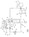
- Fig. 1 shows a schematic block diagram of a fuel cell heater 10, which generates electricity by the conversion of H 2 in a fuel cell 12. The conversion also creates heat that is available for further use.
- the hydrogen required for the fuel cell 12 is recovered from natural gas.
- natural gas is converted under supply of liquid water 14 at temperatures of 500 ° C to 800 ° C in a hydrogen-rich reformate.
- the hydrogen-rich reformate is commonly referred to as gas 2 and has, for example, the following composition: Gas components (%) H 2 74.81 CH 4 0.56 C 2 H 6 0.00 C 3 H 8 0.00 C 4 H 10 0.00 CO 0.00 CO 2 19.72 N 2 proxy 4.91 N 2 anode 0.00
- a burner 16 is used for the provision of the process heat in the reformer.
- This burner can be designed as an integral part of the reformer 18 or as a separate component.
- Fig. 1 shows the amount of heat 20 transferred from the burner 16 to the reformer.
- a gas fine cleaning 22 which is also referred to as selective oxidation (Selox) or as preferential oxidation (PrOx), with the addition of atmospheric oxygen 24, the remaining CO content is reduced to a harmless for the catalyst range, which is in the range of a few ppm .
- the selective oxidation which occurs at about 100 ° C, water exits as a product and is discharged to 26.
- the gas quality thus obtained can be added to the fuel cell 12 without the risk of degeneration of the catalyst.
- the gas 3 is returned to the reformer burner 16 for thermal utilization.
- the gas path from a gas connection via reformer, PrOx stage and possibly via the fuel cell is referred to as gas treatment.
- an ionization sensor 30 having an ionization electrode in the flame area.
- the ionization current flowing via the electrode 30 is applied to a signal evaluation unit 32.
- a signal evaluation unit 32 At the signal evaluation unit is also a measured at the reformer 18 temperature value 34 at.
- the signal evaluation unit 32 determines from the incoming input variables, of which only the ionization current and the reformer temperature 34 in FIG Fig. 1 are shown by way of example, an actual lambda value for the air / gas mixture in the burner 16.
- a control unit 38 determines manipulated variables for the air and gas supply from the incoming actual value 36 and a desired value 38 specified by a control unit (not shown).
- the air is supplied via the air channel 42, wherein the actuating signal 46 controls a fan 44 in the air passage 42.
- the actuating signal 48 activates a valve 50 in the gas supply 52 for the burner 16.
- the gas conditioning system undergoes various operating conditions.
- the burner 16 is supplied with pure natural gas to warm up the system.
- the warm-up phase is maintained until the reformer 18 has reached a temperature from which water 14 can be added to the reformer 18, without the risk of Auskondensierens.
- water 14 and process gas are added via the gas line 54 to the reformer 18.
- the valve 56 is activated accordingly.
- the reformate formed in the reformer displaces the hitherto in the reformer inert gas and supplies the inert gas via the Proxch 22 and the three-way valve 58 to the burner 16.
- the three-way valve 58 is hereby set so that no gas enters the fuel cell 12, but the displaced from the reformer 18 gas is supplied to the burner 16. Consequently, a dilution occurs at the burner due to the supply of the inert gas, which is perceived as a change in the air ratio.
- the gas composition is dependent on the reformer temperature.
- the burner is supplied with gas 2 until the gas quality is at a level to be supplied to the fuel cell. This period can range from a few seconds to several minutes, but it is also possible to direct the reformate to the fuel cell immediately.
- the three-way valve 58 is set to supply it to the fuel cell 12.
- inert gas is also initially present in the fuel cell for safety reasons. This must also be displaced from the reformate and is fed via the line 28 to the burner 16. During this displacement, the burner is further supplied with gas 1 via the line 52, the valve 50 and the line 60 in order to prevent the flame being torn off.
- the inert gas from the fuel cell 12 can be generated by reacting H 2 with this stream. Since the fuel cell only converts part of the H 2 into electricity, gas 3 is available at the anode. In the normal operating state, the heat requirement of the reformer 18 is covered with the gas 3, which is supplied via the line 28 to the burner 16. Here then the gas supply 50 is closed.
- the degree of conversion of H 2 in the fuel cell is also referred to as fuel utilization (FU) and can usually be in the range between 60% and 100%. At a certain degree of conversion, the burner 16 is still enough gas 3 available to cover the heat demand of the reformer 18. In contrast, at a high hydrogen conversion, the energy content of gas 3 is too low to provide the reforming process with sufficient heat. In this case, the burner is additionally supplied with gas 1. It can the Reformer temperature can be used as a control variable for the additional amount of gas gas 1.
- the reformer burner is supplied with different fuel gases during the various phases of operation, which can change suddenly or continuously merge. Also, the burner pure natural gas various quality can be supplied as well as hydrogen-rich reformate with different proportions of H 2 CH 4 , CO 2 and N 2 .
- the ionization sensor 30 For each fuel gas or gas composition, which is supplied to the burner, in each case an air ratio is set, which ensures a complete and clean combustion.
- the ionization sensor 30 To monitor the air ratio, the ionization sensor 30 is used. Its output signal shows a characteristic change in the air ratio.
- the ionization signal For the pure natural gas operation, there is a simple relationship for the height of the signal and the air ratio, which in Fig. 2 is shown by way of example.
- the ionization signal also changes in connection with the methane content. This course prevents an unambiguous assignment of a specific lambda value (cf. Fig. 3 ). So the signal at different Load levels and different methane content have quite identical values. In order to be able to make a clear assignment of the signal, additional boundary conditions are considered according to the invention.
- the reformer temperature is decisive for the degree of conversion of methane. From the degree of conversion can be reversed the Restmethangehalt determine so that the dependence of this Restmethangehalts of the reformer temperature with sufficient accuracy allows a clear resolution of the air ratio.
- the reformate is fed with air-oxygen 24 in the selective oxidation 22.
- the unwanted CO is reacted with air-oxygen to H 2 O 26 and CO 2 .
- the reaction educts and the remaining air-nitrogen dilute the reformate, resulting, inter alia, in a percentage Restmethangehaltverschiebung. Due to the exact knowledge of the amount of Prox air, this dilution effect can be taken into account in the evaluation of the ionization signal.
Landscapes
- Engineering & Computer Science (AREA)
- Chemical & Material Sciences (AREA)
- Sustainable Energy (AREA)
- Life Sciences & Earth Sciences (AREA)
- Manufacturing & Machinery (AREA)
- Sustainable Development (AREA)
- Chemical Kinetics & Catalysis (AREA)
- Electrochemistry (AREA)
- General Chemical & Material Sciences (AREA)
- Combustion & Propulsion (AREA)
- Mechanical Engineering (AREA)
- General Engineering & Computer Science (AREA)
- Fuel Cell (AREA)
- Hydrogen, Water And Hydrids (AREA)
- Regulation And Control Of Combustion (AREA)
Description
- Die vorliegende Erfindung betrifft ein Verfahren zur Bestimmung einer Luftzahl bei einem Brenner für ein Brennstoffzellenheizgerät ebenso wie ein Brennstoffzellenheizgerät.
- Brennstoffzellen, wie beispielsweise Polymermembranbrennstoffzellen, sind hinreichend bekannt. Brennstoffzellenheizgeräte zur dezentralen Energieversorgung werden über einen Gasanschluß mit Erdgas versorgt, wobei der Wasserstoff aus wasserstoffhaltigen Verbindungen des Erdgases reformiert wird. In einem Reformator werden in Anwesenheit eines Katalysators die· Kohlenwasserstoffe (CnHm) des Erdgases endotherm unter Zugabe von Wasserdampf reformiert, wobei Kohlendioxid (CO2) und Wasserstoff (H2) entsteht.
- Das Reformat enthält auch Reste von Kohlenmonoxid (CO), welches in einer nachgeschalteten Gasfeinreinigung unter Zugabe von Sauerstoff (O2) exotherm selektiv oxidiert wird. Dabei entsteht Kohlendioxid (CO2) und Wasser (H2O). Für die endotherme Dampfreformation wird ein Gasbrenner eingesetzt.
- Derartige Reformatoren sind beispielsweise in
EP 0 922 666 B1 ,DE 102 13 326 A1 undEP 1094 031 beschrieben. - Aus
DE 196 18 573 C1 ist ein Verfahren und eine Einrichtung zum Betrieb eines Gasgebläsebrenners bekannt, bei dem das als Lambda bezeichnete Gas-LuftVerhältnis innerhalb eines vorgegebenen Intervalls gehalten wird. Zur Regelung der Luftzahl ist im Flammenbereich des Brenners eine Ionisationselektrode angeordnet, die an eine Auswerteschaltung für einen zwischen Brenner und Ionisationselektrode fließenden Strom angeschlossen ist. Die Auswerteschaltung bildet aus einem von der Verbrennung abhängigen Ionisationsstrom eine Ionisationsspannung, die an eine Regelschaltung angelegt wird. Die Ionisationsspannung wird dann abhängig davon, ob ein höherkälorisches Gas oder ein niederkalorisches Gas verbrannt wird, zur Regelung eines Gas- und/oder Luftvolumenstroms in dem Brenner verwendet. - Aus
EP 1 186 831 B1 ist ein Luftzahlregler für einen Brenner bekannt, bei dem mit einem Sensor die Qualität der Verbrennung erfaßt wird. Ein Sensorauswerter erzeugt ein Sensorsignal, das an einer Steuereinheit anliegt. In der Steuereinheit sind Kenndaten zu dem Verhalten der Stellglieder gespeichert. Wenn während des Startvorgangs des Brenners oder aus anderen Gründen das Ionisationssignal nicht repräsentativ für die Verbrennung ist, wird das Luft-Gasverhältnis nicht geregelt, sondern gesteuert. Nach einer Vorspülzeit wird dann ein fiktives Stellsignal vorgegeben, um möglichst schnell in die Nähe des optimal geregelten Werts zu gelangen. - Der Erfindung liegt die Aufgabe zugrunde, ein Verfahren zur Bestimmung einer Luftzahl bei einem Brenner für ein Brennstoffzellenheizgerät bereitzustellen, das auch während der Startphase des Systems und bei Änderung der Gaszusammensetzung eine zuverlässige Steuerung eines Brenners in einem Brennstoffzellenheizgerät erlaubt.
- Erfindungsgemäß wird die Aufgabe durch ein Verfahren mit Merkmalen aus Anspruch 1 sowie durch ein Brennstoffzellenheizgerät mit den Merkmalen aus Anspruch 9 gelöst.
- Das erfindungsgemäße Verfahren betrifft die Bestimmung der Luftzahl bei einem Brenner für ein Brennstoffzellenheizgerät. Der Brenner ist mit einem Ionisationssensor im Flammenbereich versehen und wird durch mindestens zwei unterschiedliche Gase gespeist. Eines dieser Gase wird dem Brenner aus einer Gasaufbereitung zugeführt und ist in seiner Zusammensetzung zeitlich veränderlich, beispielsweise während eines Startvorgangs des Geräts. Ein Meßsignal des Ionisationssensors wird abhängig von einer oder mehreren Zustandsgrößen der Gasaufbereitung in einen Ist-Wert für die Luftzahl umgerechnet. Das veränderliche Gas stammt im wesentlichen aus der Gasaufbereitung. Der Erfindung liegt die Erkenntnis zugrunde, daß die von einer Ionisationselektrode erfaßten Signale bei einer entsprechenden Berücksichtigung mindestens einer weiteren Zustandsgröße der Gasaufbereitung zuverlässige und reproduzierbare Signale für den Ist-Wert der Luftzahl liefern, auch wenn mit einem veränderlichen Gasgemisch gearbeitet wird. Im Gegensatz zu den bekannten Brennern mit Ionisationssensor erfolgt bei dem erfindungsgemäßen Verfahren eine Auswertung des Meßsignals, um einen Ist-Wert für die aktuelle Luftzahl bei einer veränderlichen Gasmischung zu gewinnen. Bevorzugt wird der so ermittelte Ist-Wert der Luftzahl an eine Regelung für das Luft-/Gasgemisch in dem Brenner weitergeleitet.
- Als Zustandsgröße bei der Ermittlung des Ist-Werts der Luftzahl wird die Zusammensetzung des veränderlichen Gases aus der Gasaufbereitung berücksichtigt, insbesondere der Methangehalt des Gases. In einer bevorzugten Ausgestaltung wird bei dem erfindungsgemäßen Verfahren der Methangehalt abhängig von der Temperatur eines Reformers bestimmt. Im Ergebnis führt das erfindungsgemäße Verfahren also dazu, daß sich aus dem Meßsignal des Ionisationssensors und einem Temperaturwert für den Reformer zuverlässig ein Lambda-Ist-Wert bestimmen läßt. Als weitere Zustandsgröße der Gasaufbereitung, die für die Bestimmung des Ist-Wertes der Luftzahl herangezogen werden kann, ist der N2-Anteil aus einer Gasfeinreinigung sowie die zu erwartende Brenngasmenge ebenso wie der Wasserstoffumsatz in der Brennstoffzelle bzw. den Brennstoffzellen geeignet.
- Die vorliegende Aufgabe wird ebenfalls durch ein Brennstoffzellenheizgerät gelöst, mit einem Brenner, der einen Ionisationssensor im Flammenbereich aufweist. Dem Brenner werden zwei verschiedene Gase zugeführt, wobei eines dieser Gase aus der Gasaufbereitung stammt und in seiner Zusammensetzung veränderlich ist. Eine Signalauswerteeinheit wertet das Meßsignal des Ionisationssensors aus und ermittelt einen Ist-Wert für die Luftzahl, wobei an der Signalauswerteeinheit Signale für die Größe einer oder mehrerer Zustandsgrößen der Gasaufbereitung anliegen. Das erfindungsgemäße Brennstoffzellenheizgerät erlaubt es, den Ionisationssensor in dem Brenner, der beispielsweise auch zur Flammenüberwachung eingesetzt werden kann, als Sensor für den Ist-Wert der Luftzahl zu verwenden. Hierdurch können für eine zuverlässige Ist-Wert-Bestimmung der Luftzahl beispielsweise Sauerstoffsensoren im Abgaskanal, Temperatursensoren auf der Brenneroberfläche oder aufwendige UV-Sensoren in der Brennkammer vermieden werden.
- In einer bevorzugten Weiterbildung besitzt das Brennstoffzellenheizgerät eine Regelungseinheit, die abhängig von dem ermittelten Ist-Wert für die Luftzahl eine der Verbrennung zugeführte Luftmenge und/oder eine zugeführte Gasmenge einstellt.
- In einer bevorzugten Weiterführung besitzt das Brennstoffzellenheizgerät in einem Reformer mindestens einen Temperatursensor zur Bestimmung eines Methangehalts in dem veränderlichen Gas. Die Größe des Temperaturwerts liegt als Eingangssignal an der Signalauswerteeinheit an, so daß der Temperaturwert und der sich daraus ergebende Methangehalt in dem Gas bei der Auswertung der Meßsignale des Ionisationssensors berücksichtigt werden können.
- Zweckmäßigerweise sind in der Signalauswerteeinheit Kennfelder für die Luftzahl abhängig von dem Meßsignal des Ionisationssensors für einen Betrieb des Brenners bei unterschiedlicher Last abgelegt. Ebenfalls können alternativ oder zusätzlich Kennfelder für unterschiedliche Wasserstoffumsätze in der bzw. den Brennstoffzellen vorgesehen sein. Auch ist es zweckmäßig, in der Signalauswerteeinheit Kennfelder für die Luftzahl abhängig von dem Meßsignal des Ionisationssensors für unterschiedliche Arten des verwendeten Brenngases vorzusehen, zweckmäßigerweise wird Erdgas als Brenngas eingesetzt.
- Bevorzugt ist der Brenner als ein Flächenbrenner vorgesehen, bei dem die Flamme beispielsweise durch ein Gewebe bzw. durch ein Metallgewebe-Vlies hindurchtritt. Diese Brenner besitzen einen großen zulässigen Lambda-Bereich, ohne daß eine Instabilität der Flamme auftritt.
- Eine bevorzugte Ausführungsform des Brennstoffzellenheizgeräts wird nachfolgend in einem vereinfachten Blockschaltbild dargestellt.
- Es zeigt:
- Fig. 1
- eine schematische Blockansicht des Brennstoffzellenheizgeräts,
- Fig. 2
- das Ionisationssignal in Abhängigkeit von der Luftzahl Lambda,
- Fig. 3
- das Ionisationssignal in Abhängigkeit vom Methangehalt und
- Fig. 4
- den Ionisationsstrom in Abhängigkeit von einer Brenngasmenge.
-
Fig. 1 zeigt eine schematische Blockansicht eines Brennstoffzellenheizgeräts 10, das durch den Umsatz von H2 in einer Brennstoffzelle 12 elektrischen Strom erzeugt. Bei der Umwandlung entsteht zusätzlich Wärme, die für eine weitere Nutzung zur Verfügung steht. Der für die Brennstoffzelle 12 benötigte Wasserstoff wird aus Erdgas gewonnen. In einem Dampfreformer wird Erdgas unter Zuführung von flüssigem Wasser 14 bei Temperaturen von 500 °C bis 800 °C in ein wasserstoffreiches Reformat umgewandelt. Das wasserstoffreiche Reformat wird üblicherweise als Gas 2 bezeichnet und besitzt beispielsweise die folgende Zusammensetzung:Gasbestandteile (%) H2 74,81 CH4 0,56 C2H6 0,00 C3H8 0,00 C4H10 0,00 CO 0,00 CO2 19,72 N2-Prox 4,91 N2-Anode 0,00 - Für die Bereitstellung der Prozeßwärme im Reformer wird ein Brenner 16 verwendet. Dieser Brenner kann als integraler Bestandteil des Reformers 18 oder als eigenständige Komponente ausgeführt sein.
Fig. 1 zeigt die vom Brenner 16 in den Reformer übertragene Wärmemenge 20. - Bei der Reformierung erfolgt keine vollständige Umsetzung von Erdgas in H2 und CO2, vielmehr bildet sich als Zwischenprodukt auch Kohlenmonoxid. Da Kohlenmonoxid am Katalysator der Brennstoffzelle 12 zur Vergiftungserscheinungen führt, wird in mehreren nachgeschalteten Prozeßstufen der Kohlenmonoxidgehalt schrittweise reduziert, indem eine Umsetzung zu Kohlendioxid erfolgt. Diese Prozeßstufen werden auch als Shift-Stufen bezeichnet, wobei unter zusätzlicher Bildung von H2 der CO-Gehalt auf unter 1 % reduziert werden kann. In einer Gasfeinreinigung 22, die auch als selektive Oxidation (Selox) oder als Preferential Oxidation (PrOx) bezeichnet wird, wird unter Zugabe von Luftsauerstoff 24 der verbleibende CO-Gehalt auf einen für den Katalysator unschädlichen Bereich reduziert, der im Bereich von wenigen ppm liegt. Bei der selektiven Oxidation, die bei ungefähr 100 °C erfolgt, tritt Wasser als Produkt aus und wird an 26 abgeführt. Die so gewonnene Gasqualität kann der Brennstoffzelle 12 zugefügt werden, ohne daß die Gefahr einer Degeneration des Katalysators besteht.
- In Brennstoffzellen wird, unter Freisetzung von Wärme, Wasserstoff in elektrische Energie umgewandelt (nicht dargestellt). Dieser Umsatz wird auch als Wasserstoffumsatz bezeichnet und hängt von der konstruktiven Ausgestaltung der Brennstoffzelle ab. Das in der Brennstoffzelle nicht umgesetzte Reformat verläßt über Leitung 28 anodenseitig die Brennstoffzelle 12. Das nicht umgesetzte Reformat wird als Gas 3 bezeichnet und besitzt im wesentlichen die nachfolgend angegebene Zusammensetzung.
Gasbestandteile (%) H2 52,73 CH4 0,99 C2H6 0,00 C3H8 0,00 C4H10 0,00 CO 0,00 CO2 34,76 N2-Prox 8,64 N2-Anode 2,88 - Das Gas 3 wird zur thermischen Verwertung dem Reformerbrenner 16 wieder zugeführt. Der Gasweg von einem Gasanschluß über Reformer, PrOx-Stufe und eventuell über die Brennstoffzelle wird als Gasaufbereitung bezeichnet.
- In dem Reformerbrenner 16 ist ein Ionisationssensor 30 vorgesehen, der eine Ionisationselektrode im Flammenbereich besitzt. Der über die Elektrode 30 fließende Ionisationsstrom liegt an einer Signalauswerteeinheit 32 an. An der Signalauswerteeinheit liegt ebenfalls ein am Reformer 18 gemessener Temperaturwert 34 an. Die Signalauswerteeinheit 32 bestimmt aus den eingehenden Eingangsgrößen, von denen lediglich der Ionisationsstrom und die Reformertemperatur 34 in
Fig. 1 beispielhaft dargestellt sind, einen Lambda-Ist-Wert für das Luft-/Gasgemisch im Brenner 16. - Eine Regelungseinheit 38 bestimmt aus dem eingehenden Ist-Wert 36 und einem von einer Steuereinheit (nicht dargestellt) vorgegebenen Soll-Wert 38 Stellgrößen für die Luft- und Gaszufuhr. Die Luftzufuhr erfolgt über den Luftkanal 42, wobei das Stellsignal 46 ein Gebläse 44 in dem Luftkanal 42 ansteuert. Das Stellsignal 48 steuert ein Ventil 50 in der Gaszufuhr 52 für den Brenner 16 an.
- Das Gasaufbereitungssystem durchläuft verschiedene Betriebszustände. In der Startphase des Systems, in der ein Aufwärmen des Reformers und der Shiftstufen erfolgt, wird der Brenner 16 mit reinem Erdgas versorgt, um das System aufzuwärmen. Die Aufwärmphase wird solange beibehalten, bis der Reformer 18 eine Temperatur erreicht hat, ab der Wasser 14 dem Reformer 18 zugegeben werden kann, ohne daß die Gefahr eines Auskondensierens besteht.
- Nachdem die Startphase des Systems und das Aufwärmen des Reformers abgeschlossen ist, wird Wasser 14 und Prozeßgas über die Gasleitung 54 dem Reformer 18 zugegeben. Das Ventil 56 wird entsprechend angesteuert. Das im Reformer gebildete Reformat verdrängt das bis dahin im Reformer befindliche Inertgas und führt das Inertgas über die Proxstufe 22 und des Dreiwegeventils 58 dem Brenner 16 zu. Das Dreiwegeventil 58 wird hierbei so gestellt, daß kein Gas in die Brennstoffzelle 12 eintritt, sondern das aus dem Reformer 18 verdrängte Gas dem Brenner 16 zugeführt wird. Am Brenner tritt folglich durch die Zuleitung des Inertgases eine Verdünnung auf, die wie eine Veränderung der Luftzahl wahrgenommen wird.
- Die Versorgung des Brenners mit Gas 1 über Leitung 52, Ventil 50 und Leitung 60 bleibt während des Verdrängungsvorgangs erhalten, bis das Inertgas verdrängt wurde und nur noch Reformat dem Brenner zugeführt wird.
- Bei vollständiger Verdrängung des Inertgases wird dem Brenner Reformat zur Verfügung gestellt. Die Gaszusammensetzung ist dabei abhängig von der Reformertemperatur. Der Brenner wird solange mit Gas 2 versorgt, bis die Gasqualität sich auf einem Niveau befindet, um der Brennstoffzelle zugeführt zu werden. Dieser Zeitraum kann sich von wenigen Sekunden bis mehreren Minuten erstrecken, es ist aber auch möglich das Reformat sofort an die Brennstoffzelle zu leiten.
- Sobald Gas 2 die erforderliche Qualität erreicht hat, wird das Dreiwegeventil 58 gestellt, um es der Brennstoffzelle 12 zuzuführen. Auch in der Brennstoffzelle befindet sich wie bei dem Reformer 18 aus Sicherheitsgründen zunächst Inertgas. Dieses muß ebenfalls vom Reformat verdrängt werden und wird über die Leitung 28 dem Brenner 16 zugeführt. Während dieser Verdrängung wird der Brenner weiter mit Gas 1 über die Leitung 52, das Ventil 50 und die Leitung 60 versorgt, damit ein Abreißen der Flamme verhindert wird.
- Nach dem Verdrängen des Inertgases aus der Brennstoffzelle 12 kann durch Umsetzen von H2 mit dieser Strom erzeugt werden. Da die Brennstoffzelle nur einen Teil des H2 in Strom umsetzt, steht an der Anode Gas 3 zur Verfügung. Im normalen Betriebszustand wird der Wärmebedarf des Reformers 18 mit dem Gas 3 gedeckt, das über die Leitung 28 dem Brenner 16 zugeführt wird. Hierbei ist dann die Gaszufuhr 50 geschlossen. Der Umsatzgrad von H2 in der Brennstoffzelle wird auch als Fuel Utilisation (FU) bezeichnet und kann üblicherweise im Bereich zwischen 60 % und 100 % liegen. Bei einem bestimmten Umsetzungsgrad steht dem Brenner 16 noch genügend Gas 3 zur Verfügung, um den Wärmebedarf des Reformers 18 zu decken. Dagegen ist bei einer hohen Wasserstoffumsetzung der Energiegehalt von Gas 3 zu gering, um den Reformerprozeß mit ausreichender Wärme zu versorgen. In diesem Fall wird dem Brenner zusätzlich Gas 1 zugeführt. Dabei kann die Reformertemperatur als Regelgröße für die zusätzliche Gasmenge von Gas 1 genutzt werden.
- Für den einwandfreien Betrieb der Brennstoffzelle muß eine Mindestgasqualität gewährleistet werden. Wird dieser Wert überschritten, muß der Reformatfluß von der Zelle weg geschaltet werden. Dieser Wechsel beim Überschreiten eines CO-Werts erfolgt innerhalb der Schaltzeit der entsprechenden Ventile, beispielsweise 58, findet also ohne Übergang statt. Bei jedem anderen kurzzeitigen Störfall, wie er beispielsweise durch einen Lastabwurf oder dergleichen auftritt, wird analog das gesamte produzierte Reformat an der Brennstoffzelle vorbei auf den Brenner geführt.
- Der Reformerbrenner wird während der verschiedenen Betriebsphasen mit unterschiedlichen Brenngasen versorgt, welche plötzlich wechseln können oder kontinuierlich ineinander übergehen. Ebenfalls kann dem Brenner reines Erdgas verschiedener Qualität ebenso zugeführt werden, wie wasserstoffreiches Reformat mit unterschiedlichen Anteilen von H2CH4, CO2 und N2.
- Für jedes Brenngas bzw. Gaszusammensetzung, welches dem Brenner zugeführt wird, ist jeweils eine Luftzahl einzustellen, welche eine vollständige und saubere Verbrennung sicherstellt. Zur Überwachung der Luftzahl wird der Ionisationssensor 30 eingesetzt. Dessen Ausgangssignal zeigt eine charakteristische Veränderung in der Luftzahl. Für den reinen Erdgasbetrieb ergibt sich ein einfacher Zusammenhang für die Höhe des Signals und die Luftzahl, der in
Fig. 2 beispielhaft dargestellt ist. Bei der Verwendung von Brenngas mit unterschiedlichen Zusammensetzungen ändert sich das Ionisationssignal zusätzlich im Zusammenhang mit dem Methangehalt. Dieser Verlauf verhindert eine eindeutige Zuordnung eines bestimmten Lambda-Werts (vgl.Fig. 3 ). So kann das Signal bei verschiedenen Laststufen und unterschiedlichem Methangehalt durchaus identische Werte aufweisen. Um eine eindeutige Zuordnung des Signals vornehmen zu können, werden gemäß der Erfindung zusätzliche Randbedingungen berücksichtigt. - Die Reformertemperatur ist hierbei maßgeblich bestimmend für den Umsatzgrad an Methan. Aus dem Umsatzgrad läßt sich im Umkehrschluß der Restmethangehalt bestimmen, so daß die Abhängigkeit dieses Restmethangehalts von der Reformertemperatur mit hinreichender Genauigkeit eine eindeutig Auflösung der Luftzahl erlaubt.
- Zur Gasfeinreinigung des Reformats wird bei der selektiven Oxidation 22 dem Reformat Luft-Sauerstoff 24 zugeführt. An einem Katalysator wird das unerwünschte CO mit Luft-Sauerstoff zu H2O 26 und CO2 abreagiert. Die Reaktionsedukte und der verbleibende Luft-Stickstoff verdünnen das Reformat, wodurch sich u.a. auch eine prozentuale Restmethangehaltverschiebung ergibt. Durch die genaue Kenntnis der Prox-Luftmenge kann dieser Verdünnungseffekt bei der Auswertung des Ionisationssignals mit berücksichtigt werden.
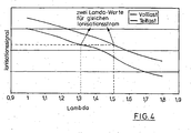
- Neben dem prozentualen Methangehalt im Brenngas hat auch die absolute Brenngasmenge einen Einfluß auf die Höhe des Ionisationssignals, wie in
Fig. 4 für einen Vollastbetrieb und einen Teillastbetrieb des Brenners 16 beispielhaft dargestellt ist. Über die Auswertung der zugeführten Prozeßgasmenge kann ermittelt werden, wieviel Reformat erzeugt wird. Aus der Stromproduktion der Brennstoffzelle läßt sich dann rechnerisch in Kombination mit der angebotenen Reformatmenge die zu erwartende Brenngasmenge ermitteln, so daß wieder eine eindeutige Auflösung des Ionisationssignals zu genau einem Lambda-Wert möglich ist.
Claims (14)
- Verfahren zur Bestimmung einer Luftzahl bei einem Brenner für ein Brennstoffzellenheizgerät, der einen Ionisationssensor (30) im Flammbereich aufweist und dem zwei unterschiedliche Gase zur Verbrennung zugeführt werden, von denen ein Gas aus einer Gasaufbereitung stammt, dadurch gekennzeichnet, daß ein Meßsignal des Ionisationssensors (30) abhängig von einer oder mehreren Zustandsgrößen (34) der Gasaufbereitung in einen Ist-Wert (36) für die Luftzahl umgewandelt wird und abhängig von dem Ist-Wert für die Luftzahl eine Regelung des Luft-Gasgemisches in dem Brenner erfolgt.
- Verfahren nach Anspruch 1, dadurch gekennzeichnet, daß als Zustandsgröße zur Ermittlung des Ist-Werts der Luftzahl die Zusammensetzung des Gases aus der Gasaufbereitung berücksichtigt wird.
- Verfahren nach einem der Ansprüche 1 oder 2, dadurch gekennzeichnet, daß als Zustandsgröße der Methangehalt des Gases aus der Gasaufbereitung berücksichtigt wird.
- Verfahren nach Anspruch 3, dadurch gekennzeichnet, daß der Methangehalt abhängig von der Temperatur eines Reformers (18) und/oder der Prozeßgasmenge bestimmt wird.
- Verfahren nach einem der Ansprüche 1 bis 4, dadurch gekennzeichnet, daß als Zustandsgröße der N2-Anteil des Gases aus einer Gasfeinreinigung (22) bestimmt wird.
- Verfahren nach einem der Ansprüche 1 bis 5, dadurch gekennzeichnet, daß bei der Bestimmung des Ist-Werts für die Luftzahl die zu erwartende Gasmenge des Gases aus der Gasaufbereitung berücksichtigt wird.
- Verfahren nach einem der Ansprüche 1 bis 6, dadurch gekennzeichnet, daß als Zustandsgröße der Wasserstoffumsatz in der Brennstoffzelle berücksichtigt wird.
- Brennstoffzellenheizgerät mit einem Brenner, der einen Ionisationssensor (30) im Flammenbereich aufweist und dem zwei unterschiedliche Gases zur Verbrennung zugeführt werden, von denen ein Gas aus einer Gasaufbereitung stammt, dadurch gekennzeichnet, daß eine Signalauswerteeinheit (32) vorgesehen ist, die das Meßsignal des Ionisationssensors (30) auswertet und einen Ist-Wert für die Luftzahl ermittelt, wobei an der Signalauswerteeinheit (32) Signale (34) einer oder mehrerer Zustandsgrößen der Gasaufbereitungseinrichtung anliegen und das Meßsignal des Ionisationssensors (30) abhängig von der einen oder den mehreren Zustandsgrößen der Gasaufbereitungseinrichtung in einen Ist-Wert für die Luftzahl umgewandelt wird, und eine Regelungseinheit vorgesehen ist, die abhängig von dem so ermittelten Ist-Wert für die Luftzahl eine der Verbrennung zugeführte Luftmenge und/öder eine zugeführte Gasmenge einstellt.
- Brennstoffzellenheizgerät nach Anspruch 8, dadurch gekennzeichnet, daß in einem Reformer (18) mindestens ein Temperatursensor zur Bestimmung eines Methangehalts in dem Gas aus der Gasaufbereitung vorgesehen ist.
- Brennstoffzellenheizgerät nach einern der Ansprüche 8 oder 9, dadurch gekennzeichner, daß in der Auswerteeinheit (32) Kennfelder für die Luftzahl abhängig von dem Meßsignal des Ionisationssensors für unterschiedliche Lasten des Brenners abgelegt sind.
- Brennstoffzellenheizgerät nach einem der Ansprüche 8 bis 10, dadurch gekennzeichnet, daß in der Auswerteeinheit Kennfelder für die Luftzahl abhängig von dem Meßsignal des Ionisationssensors für unterschiedliche Methangehalte des Gases abgelegt sind.
- Brennstoffzellenheizgerät nach einem der Ansprüche 8 bis 11, dadurch gekennzeichnet, daß in der Auswerteeinheit (32) Kennfelder für die Luftzahl abhängig von dem Meßsignal des Ionisationssensors für unterschiedliche Wasserstoffumsätze in der Brennstoffzelle abgelegt sind.
- Brennstoffzellenheizgerät nach einem der Ansprüche 8 bis 12, dadurch gekennzeichnet, daß in der Auswerteeinheit (32) Kennfelder für die Luftzahl abhängig von einem Meßsignal des Ionisationssensors abhängig von einer Art des verwendeten Erdgases abgelegt ist.
- Brennstoffzellenheizgerät nach einem der Ansprüche 8 bis 13, dadurch gekennzeichnet, daß als Brenner ein Flächenbrenner vorgesehen ist.
Applications Claiming Priority (2)
| Application Number | Priority Date | Filing Date | Title |
|---|---|---|---|
| DE102004059494A DE102004059494C5 (de) | 2004-12-10 | 2004-12-10 | Verfahren zur Bestimmung einer Luftzahl bei einem Brenner für ein Brennstoffzellenheizgerät sowie Brennstoffzellenheizgerät |
| PCT/EP2005/013175 WO2006061228A1 (de) | 2004-12-10 | 2005-12-08 | Verfahren zur bestimmung einer luftzahl bei einem brenner für ein brennstoffzellenheizgerät sowie brennstoffzellenheizgerät |
Publications (2)
| Publication Number | Publication Date |
|---|---|
| EP1817814A1 EP1817814A1 (de) | 2007-08-15 |
| EP1817814B1 true EP1817814B1 (de) | 2009-02-18 |
Family
ID=36097217
Family Applications (1)
| Application Number | Title | Priority Date | Filing Date |
|---|---|---|---|
| EP05850243A Expired - Lifetime EP1817814B1 (de) | 2004-12-10 | 2005-12-08 | Verfahren zur bestimmung einer luftzahl bei einem brenner für ein brennstoffzellenheizgerät sowie brennstoffzellenheizgerät |
Country Status (12)
| Country | Link |
|---|---|
| US (1) | US7931467B2 (de) |
| EP (1) | EP1817814B1 (de) |
| JP (1) | JP4988590B2 (de) |
| KR (2) | KR100986246B1 (de) |
| AT (1) | ATE423398T1 (de) |
| CA (1) | CA2602059C (de) |
| DE (3) | DE202004020319U1 (de) |
| DK (1) | DK1817814T3 (de) |
| ES (1) | ES2322488T3 (de) |
| NO (1) | NO20073517L (de) |
| PT (1) | PT1817814E (de) |
| WO (1) | WO2006061228A1 (de) |
Families Citing this family (10)
| Publication number | Priority date | Publication date | Assignee | Title |
|---|---|---|---|---|
| DE102006042995A1 (de) * | 2006-09-13 | 2008-03-27 | Enerday Gmbh | Verfahren zur Ermittlung eines Anodenumsatzgrads in einem Brennstoffzellensystem |
| DE102006043350B3 (de) * | 2006-09-15 | 2008-04-17 | Enerday Gmbh | Verfahren und System zur Regelung/Steuerung einer Gesamtluftverhältniszahl eines Reformers |
| DE102009004278A1 (de) * | 2009-01-05 | 2010-07-15 | Synthesechemie Dr. Penth Gmbh | Messgerät für geringe Kohlenwasserstoffkonzentrationen |
| JP4759656B2 (ja) | 2009-09-04 | 2011-08-31 | パナソニック株式会社 | 水素発生装置とその起動方法 |
| US9222410B2 (en) | 2011-04-13 | 2015-12-29 | General Electric Company | Power plant |
| WO2012153483A1 (ja) * | 2011-05-06 | 2012-11-15 | パナソニック株式会社 | 発電装置及びその運転方法 |
| DE102012023438B4 (de) * | 2012-11-30 | 2015-06-03 | Robert Bosch Gmbh | Verfahren zum Betrieb eines Brennstoffzellensystems und Brennstoffzellensystem für die Durchführung des Verfahrens |
| EP2843214B1 (de) | 2013-05-29 | 2021-06-23 | Mems Ag | Verfahren, Sensor und Regelvorrichtung zur Regelung gasbetriebener Energiewandleranlagen |
| DE102020104084A1 (de) * | 2020-02-17 | 2021-08-19 | Ebm-Papst Landshut Gmbh | Verfahren zur Überwachung und Regelung eines Prozesses einer Gastherme und Gastherme |
| DE102021118406A1 (de) | 2021-07-16 | 2023-01-19 | Viessmann Climate Solutions Se | Brennervorrichtung und Verfahren zum Betrieb einer Brennervorrichtung |
Family Cites Families (21)
| Publication number | Priority date | Publication date | Assignee | Title |
|---|---|---|---|---|
| JPS5899614A (ja) * | 1981-12-07 | 1983-06-14 | Matsushita Electric Ind Co Ltd | 燃焼検知装置 |
| DE10213326A1 (de) | 2002-03-25 | 2003-10-16 | Viessmann Werke Kg | Apparat zur Erzeugung von Wasserstoff |
| DE4433425C2 (de) * | 1994-09-20 | 1998-04-30 | Stiebel Eltron Gmbh & Co Kg | Regeleinrichtung zum Einstellen eines Gas-Verbrennungsluft-Gemisches bei einem Gasbrenner |
| DE59604283D1 (de) * | 1995-10-25 | 2000-03-02 | Stiebel Eltron Gmbh & Co Kg | Verfahren und Schaltung zur Regelung eines Gasbrenners |
| DE19618573C1 (de) * | 1996-05-09 | 1997-06-26 | Stiebel Eltron Gmbh & Co Kg | Verfahren und Einrichtung zum Betrieb eines Gasbrenners |
| JP3403416B2 (ja) | 1996-06-28 | 2003-05-06 | 松下電工株式会社 | 改質装置 |
| CA2335483C (en) | 1999-04-20 | 2005-03-29 | Tokyo Gas Co., Ltd. | Single-pipe cylindrical reformer and operation method therefor |
| DE19941978B4 (de) * | 1999-09-03 | 2005-09-22 | Stiebel Eltron Gmbh & Co. Kg | Verfahren und Einrichtung zur Erzeugung eines Synthesegases |
| US6299433B1 (en) * | 1999-11-05 | 2001-10-09 | Gas Research Institute | Burner control |
| DE10006006B4 (de) * | 1999-12-07 | 2008-12-18 | Stiebel Eltron Gmbh & Co. Kg | Kraft-Wärme-Kopplungsapparat |
| DE10001251B4 (de) * | 2000-01-14 | 2005-01-27 | Robert Bosch Gmbh | Verfahren zum Steuern oder Regeln eines Gasbrenners |
| WO2002017425A1 (en) * | 2000-08-18 | 2002-02-28 | Matsushita Electric Industrial Co., Ltd. | Fuel cell electricity generator |
| DE10059892B4 (de) | 2000-12-01 | 2010-04-08 | Stiebel Eltron Gmbh & Co. Kg | Verfahren zum Betrieb eines Kraft-Wärme-Kopplungsapparats und Kraft-Wärme-Kopplungsapparat |
| DE10125588C1 (de) * | 2001-05-25 | 2002-06-06 | Webasto Thermosysteme Gmbh | Zusatzheizgerät für ein Fahrzeug mit Erfassung der Brennstoffqualität |
| DE10132708A1 (de) * | 2001-07-05 | 2003-01-30 | Stiebel Eltron Gmbh & Co Kg | Einrichtung zum Betrieb einer Brennstoffzelle |
| JP3785380B2 (ja) * | 2002-06-28 | 2006-06-14 | 株式会社ノーリツ | 燃焼装置 |
| JP4278366B2 (ja) * | 2002-11-22 | 2009-06-10 | 荏原バラード株式会社 | 燃料処理装置、燃料処理方法および燃料電池発電システム |
| DE10324315A1 (de) | 2003-05-27 | 2004-12-16 | Siemens Building Technologies Ag | Verfahren zur Überwachung der Qualität eines von einem Reformer für den Betrieb von Brennstoffzellen gelieferten Gasgemisches |
| JP2005090856A (ja) * | 2003-09-17 | 2005-04-07 | Matsushita Electric Ind Co Ltd | 燃焼装置 |
| US7521140B2 (en) | 2004-04-19 | 2009-04-21 | Eksigent Technologies, Llc | Fuel cell system with electrokinetic pump |
| US7951500B2 (en) * | 2006-05-25 | 2011-05-31 | Siemens Energy, Inc. | Anode gas stack start-up heater and purge gas generator |
-
2004
- 2004-12-10 DE DE202004020319U patent/DE202004020319U1/de not_active Expired - Lifetime
- 2004-12-10 DE DE102004059494A patent/DE102004059494C5/de not_active Expired - Fee Related
-
2005
- 2005-12-08 KR KR1020097020812A patent/KR100986246B1/ko not_active Expired - Fee Related
- 2005-12-08 KR KR1020077015802A patent/KR20070089999A/ko not_active Ceased
- 2005-12-08 US US11/721,214 patent/US7931467B2/en not_active Expired - Fee Related
- 2005-12-08 JP JP2007544823A patent/JP4988590B2/ja not_active Expired - Fee Related
- 2005-12-08 DK DK05850243T patent/DK1817814T3/da active
- 2005-12-08 EP EP05850243A patent/EP1817814B1/de not_active Expired - Lifetime
- 2005-12-08 WO PCT/EP2005/013175 patent/WO2006061228A1/de not_active Ceased
- 2005-12-08 CA CA2602059A patent/CA2602059C/en not_active Expired - Fee Related
- 2005-12-08 ES ES05850243T patent/ES2322488T3/es not_active Expired - Lifetime
- 2005-12-08 PT PT05850243T patent/PT1817814E/pt unknown
- 2005-12-08 AT AT05850243T patent/ATE423398T1/de active
- 2005-12-08 DE DE502005006669T patent/DE502005006669D1/de not_active Expired - Lifetime
-
2007
- 2007-07-09 NO NO20073517A patent/NO20073517L/no not_active Application Discontinuation
Also Published As
| Publication number | Publication date |
|---|---|
| DE102004059494B4 (de) | 2006-10-12 |
| KR20090108673A (ko) | 2009-10-15 |
| US20090130616A1 (en) | 2009-05-21 |
| DE102004059494C5 (de) | 2008-07-24 |
| KR20070089999A (ko) | 2007-09-04 |
| EP1817814A1 (de) | 2007-08-15 |
| JP2008523549A (ja) | 2008-07-03 |
| DE202004020319U1 (de) | 2005-04-21 |
| NO20073517L (no) | 2007-07-09 |
| WO2006061228A1 (de) | 2006-06-15 |
| DK1817814T3 (da) | 2009-06-08 |
| PT1817814E (pt) | 2009-05-21 |
| US7931467B2 (en) | 2011-04-26 |
| ES2322488T3 (es) | 2009-06-22 |
| DE502005006669D1 (de) | 2009-04-02 |
| JP4988590B2 (ja) | 2012-08-01 |
| CA2602059C (en) | 2011-04-26 |
| DE102004059494A1 (de) | 2006-06-22 |
| ATE423398T1 (de) | 2009-03-15 |
| CA2602059A1 (en) | 2006-06-15 |
| KR100986246B1 (ko) | 2010-10-07 |
Similar Documents
| Publication | Publication Date | Title |
|---|---|---|
| EP0790657B1 (de) | Verfahren zum Betreiben eines Brennstoffzellensystems | |
| EP1835240B1 (de) | Verfahren zum Betreiben einer Kombination eines Heizgeräts mit einer Brennstoffzellenanlage | |
| EP1817814B1 (de) | Verfahren zur bestimmung einer luftzahl bei einem brenner für ein brennstoffzellenheizgerät sowie brennstoffzellenheizgerät | |
| DE60222962T2 (de) | Brennstoffzellenkraftanlage mit Reformer | |
| WO2006061245A1 (de) | Brennstoffzellenheizgerät sowie verfahren zum betreiben eines brennstoffzellenheizgeräts | |
| DE102016123106B4 (de) | Brennstoffzellenvorrichtung | |
| DE19847211C1 (de) | Verfahren zum Betreiben einer Reformer/CO-Oxidationseinheit | |
| DE102007019359A1 (de) | Brennstoffzellensystem und zugehöriges Startverfahren | |
| EP1519894A2 (de) | Verfahren zum starten eines gaserzeugungssystems | |
| AT407314B (de) | Brennstoffzellenanordnung | |
| EP1205991B1 (de) | Verfahren zur elektrischen Inbetriebnahme einer Brennstoffzelle | |
| DE102008004291A1 (de) | Brennstoffzellenanlage sowie Steuerungsvorrichtung und Betriebsverfahren hierfür | |
| EP1753061B1 (de) | Verfahren zum Starten einer Brennstoffzellenanlage | |
| DE102004001310A1 (de) | Verfahren zum Betrieb einer Anlage zur Wasserdampfreformierung eines Kohlenwasserstoffgases | |
| EP1986262B1 (de) | Kalibrierverfahren für eine Brennstoffzellensteuerung | |
| EP1906478A1 (de) | Brennstoffzellensystem | |
| AT413440B (de) | Verfahren zur anpassung des brenngas-luft- verhältnisses an die gasart bei einem gasbrenner | |
| EP1139473B1 (de) | Brennstoffzellensystem und Verfahren zum Betreiben eines Brennstoffzellensystems | |
| EP1207134B1 (de) | Gaserzeugungssystem für einen Reformer | |
| WO2012076136A1 (de) | Verfahren zum betrieb eines brennstoffzellensystems und brennstoffzellensystem | |
| DE10209681A1 (de) | Verfahren zum Betrieb einer Reformeranlage sowie Reformeranlage | |
| DE10054437A1 (de) | Vorrichtung und Verfahren zur Feinreinigung des Brennstoffgases für eine Brennstoffzelle | |
| WO2012062403A1 (de) | Verfahren zum betrieb eines brennstoffzellensystems | |
| DE102012201632A1 (de) | Verfahren zum Betreiben eines Brennstoffzellensystems | |
| WO2008125086A1 (de) | Verfahren zum überprüfen eines reformers und elektrische steuereinheit |
Legal Events
| Date | Code | Title | Description |
|---|---|---|---|
| PUAI | Public reference made under article 153(3) epc to a published international application that has entered the european phase |
Free format text: ORIGINAL CODE: 0009012 |
|
| 17P | Request for examination filed |
Effective date: 20070605 |
|
| AK | Designated contracting states |
Kind code of ref document: A1 Designated state(s): AT BE BG CH CY CZ DE DK EE ES FI FR GB GR HU IE IS IT LI LT LU LV MC NL PL PT RO SE SI SK TR |
|
| RIN1 | Information on inventor provided before grant (corrected) |
Inventor name: SCHILLING, LUTZ Inventor name: HOFFMANN, CHRISTIAN Inventor name: KLOSE, PHILIPP |
|
| DAX | Request for extension of the european patent (deleted) | ||
| GRAP | Despatch of communication of intention to grant a patent |
Free format text: ORIGINAL CODE: EPIDOSNIGR1 |
|
| GRAS | Grant fee paid |
Free format text: ORIGINAL CODE: EPIDOSNIGR3 |
|
| GRAA | (expected) grant |
Free format text: ORIGINAL CODE: 0009210 |
|
| AK | Designated contracting states |
Kind code of ref document: B1 Designated state(s): AT BE BG CH CY CZ DE DK EE ES FI FR GB GR HU IE IS IT LI LT LU LV MC NL PL PT RO SE SI SK TR |
|
| REG | Reference to a national code |
Ref country code: GB Ref legal event code: FG4D Free format text: NOT ENGLISH |
|
| REG | Reference to a national code |
Ref country code: CH Ref legal event code: EP |
|
| REG | Reference to a national code |
Ref country code: IE Ref legal event code: FG4D Free format text: LANGUAGE OF EP DOCUMENT: GERMAN |
|
| REF | Corresponds to: |
Ref document number: 502005006669 Country of ref document: DE Date of ref document: 20090402 Kind code of ref document: P |
|
| REG | Reference to a national code |
Ref country code: CH Ref legal event code: NV Representative=s name: ISLER & PEDRAZZINI AG |
|
| REG | Reference to a national code |
Ref country code: PT Ref legal event code: SC4A Free format text: AVAILABILITY OF NATIONAL TRANSLATION Effective date: 20090513 |
|
| REG | Reference to a national code |
Ref country code: DK Ref legal event code: T3 |
|
| REG | Reference to a national code |
Ref country code: SE Ref legal event code: TRGR |
|
| REG | Reference to a national code |
Ref country code: ES Ref legal event code: FG2A Ref document number: 2322488 Country of ref document: ES Kind code of ref document: T3 |
|
| PG25 | Lapsed in a contracting state [announced via postgrant information from national office to epo] |
Ref country code: LT Free format text: LAPSE BECAUSE OF FAILURE TO SUBMIT A TRANSLATION OF THE DESCRIPTION OR TO PAY THE FEE WITHIN THE PRESCRIBED TIME-LIMIT Effective date: 20090218 Ref country code: SI Free format text: LAPSE BECAUSE OF FAILURE TO SUBMIT A TRANSLATION OF THE DESCRIPTION OR TO PAY THE FEE WITHIN THE PRESCRIBED TIME-LIMIT Effective date: 20090218 |
|
| PG25 | Lapsed in a contracting state [announced via postgrant information from national office to epo] |
Ref country code: IS Free format text: LAPSE BECAUSE OF FAILURE TO SUBMIT A TRANSLATION OF THE DESCRIPTION OR TO PAY THE FEE WITHIN THE PRESCRIBED TIME-LIMIT Effective date: 20090618 Ref country code: LV Free format text: LAPSE BECAUSE OF FAILURE TO SUBMIT A TRANSLATION OF THE DESCRIPTION OR TO PAY THE FEE WITHIN THE PRESCRIBED TIME-LIMIT Effective date: 20090218 Ref country code: PL Free format text: LAPSE BECAUSE OF FAILURE TO SUBMIT A TRANSLATION OF THE DESCRIPTION OR TO PAY THE FEE WITHIN THE PRESCRIBED TIME-LIMIT Effective date: 20090218 |
|
| PG25 | Lapsed in a contracting state [announced via postgrant information from national office to epo] |
Ref country code: EE Free format text: LAPSE BECAUSE OF FAILURE TO SUBMIT A TRANSLATION OF THE DESCRIPTION OR TO PAY THE FEE WITHIN THE PRESCRIBED TIME-LIMIT Effective date: 20090218 |
|
| PG25 | Lapsed in a contracting state [announced via postgrant information from national office to epo] |
Ref country code: RO Free format text: LAPSE BECAUSE OF FAILURE TO SUBMIT A TRANSLATION OF THE DESCRIPTION OR TO PAY THE FEE WITHIN THE PRESCRIBED TIME-LIMIT Effective date: 20090218 Ref country code: SK Free format text: LAPSE BECAUSE OF FAILURE TO SUBMIT A TRANSLATION OF THE DESCRIPTION OR TO PAY THE FEE WITHIN THE PRESCRIBED TIME-LIMIT Effective date: 20090218 |
|
| PLBE | No opposition filed within time limit |
Free format text: ORIGINAL CODE: 0009261 |
|
| STAA | Information on the status of an ep patent application or granted ep patent |
Free format text: STATUS: NO OPPOSITION FILED WITHIN TIME LIMIT |
|
| 26N | No opposition filed |
Effective date: 20091119 |
|
| PG25 | Lapsed in a contracting state [announced via postgrant information from national office to epo] |
Ref country code: BG Free format text: LAPSE BECAUSE OF FAILURE TO SUBMIT A TRANSLATION OF THE DESCRIPTION OR TO PAY THE FEE WITHIN THE PRESCRIBED TIME-LIMIT Effective date: 20090518 |
|
| PG25 | Lapsed in a contracting state [announced via postgrant information from national office to epo] |
Ref country code: MC Free format text: LAPSE BECAUSE OF NON-PAYMENT OF DUE FEES Effective date: 20100701 |
|
| PG25 | Lapsed in a contracting state [announced via postgrant information from national office to epo] |
Ref country code: GR Free format text: LAPSE BECAUSE OF FAILURE TO SUBMIT A TRANSLATION OF THE DESCRIPTION OR TO PAY THE FEE WITHIN THE PRESCRIBED TIME-LIMIT Effective date: 20090519 |
|
| PG25 | Lapsed in a contracting state [announced via postgrant information from national office to epo] |
Ref country code: LU Free format text: LAPSE BECAUSE OF NON-PAYMENT OF DUE FEES Effective date: 20091208 |
|
| PG25 | Lapsed in a contracting state [announced via postgrant information from national office to epo] |
Ref country code: HU Free format text: LAPSE BECAUSE OF FAILURE TO SUBMIT A TRANSLATION OF THE DESCRIPTION OR TO PAY THE FEE WITHIN THE PRESCRIBED TIME-LIMIT Effective date: 20090819 |
|
| PG25 | Lapsed in a contracting state [announced via postgrant information from national office to epo] |
Ref country code: CY Free format text: LAPSE BECAUSE OF FAILURE TO SUBMIT A TRANSLATION OF THE DESCRIPTION OR TO PAY THE FEE WITHIN THE PRESCRIBED TIME-LIMIT Effective date: 20090218 |
|
| PGFP | Annual fee paid to national office [announced via postgrant information from national office to epo] |
Ref country code: CZ Payment date: 20131127 Year of fee payment: 9 Ref country code: SE Payment date: 20131217 Year of fee payment: 9 Ref country code: IE Payment date: 20131213 Year of fee payment: 9 Ref country code: PT Payment date: 20130611 Year of fee payment: 9 |
|
| PGFP | Annual fee paid to national office [announced via postgrant information from national office to epo] |
Ref country code: ES Payment date: 20131216 Year of fee payment: 9 Ref country code: TR Payment date: 20131202 Year of fee payment: 9 Ref country code: IT Payment date: 20131217 Year of fee payment: 9 Ref country code: FI Payment date: 20131216 Year of fee payment: 9 |
|
| PGFP | Annual fee paid to national office [announced via postgrant information from national office to epo] |
Ref country code: BE Payment date: 20131216 Year of fee payment: 9 |
|
| PGFP | Annual fee paid to national office [announced via postgrant information from national office to epo] |
Ref country code: GB Payment date: 20141216 Year of fee payment: 10 Ref country code: DK Payment date: 20141215 Year of fee payment: 10 Ref country code: CH Payment date: 20141216 Year of fee payment: 10 |
|
| PGFP | Annual fee paid to national office [announced via postgrant information from national office to epo] |
Ref country code: AT Payment date: 20141219 Year of fee payment: 10 Ref country code: NL Payment date: 20141215 Year of fee payment: 10 |
|
| PGFP | Annual fee paid to national office [announced via postgrant information from national office to epo] |
Ref country code: DE Payment date: 20150210 Year of fee payment: 10 |
|
| PGFP | Annual fee paid to national office [announced via postgrant information from national office to epo] |
Ref country code: FR Payment date: 20141229 Year of fee payment: 10 |
|
| REG | Reference to a national code |
Ref country code: PT Ref legal event code: MM4A Free format text: LAPSE DUE TO NON-PAYMENT OF FEES Effective date: 20150608 |
|
| PG25 | Lapsed in a contracting state [announced via postgrant information from national office to epo] |
Ref country code: BE Free format text: LAPSE BECAUSE OF NON-PAYMENT OF DUE FEES Effective date: 20141231 |
|
| PG25 | Lapsed in a contracting state [announced via postgrant information from national office to epo] |
Ref country code: FI Free format text: LAPSE BECAUSE OF NON-PAYMENT OF DUE FEES Effective date: 20141208 Ref country code: SE Free format text: LAPSE BECAUSE OF NON-PAYMENT OF DUE FEES Effective date: 20141209 Ref country code: PT Free format text: LAPSE BECAUSE OF NON-PAYMENT OF DUE FEES Effective date: 20150608 Ref country code: CZ Free format text: LAPSE BECAUSE OF NON-PAYMENT OF DUE FEES Effective date: 20141208 |
|
| REG | Reference to a national code |
Ref country code: SE Ref legal event code: EUG |
|
| REG | Reference to a national code |
Ref country code: IE Ref legal event code: MM4A |
|
| PG25 | Lapsed in a contracting state [announced via postgrant information from national office to epo] |
Ref country code: IE Free format text: LAPSE BECAUSE OF NON-PAYMENT OF DUE FEES Effective date: 20141208 |
|
| PG25 | Lapsed in a contracting state [announced via postgrant information from national office to epo] |
Ref country code: IT Free format text: LAPSE BECAUSE OF NON-PAYMENT OF DUE FEES Effective date: 20141208 |
|
| REG | Reference to a national code |
Ref country code: ES Ref legal event code: FD2A Effective date: 20160127 |
|
| PG25 | Lapsed in a contracting state [announced via postgrant information from national office to epo] |
Ref country code: ES Free format text: LAPSE BECAUSE OF NON-PAYMENT OF DUE FEES Effective date: 20141209 |
|
| REG | Reference to a national code |
Ref country code: DE Ref legal event code: R119 Ref document number: 502005006669 Country of ref document: DE |
|
| REG | Reference to a national code |
Ref country code: DK Ref legal event code: EBP Effective date: 20151231 |
|
| REG | Reference to a national code |
Ref country code: CH Ref legal event code: PL |
|
| REG | Reference to a national code |
Ref country code: AT Ref legal event code: MM01 Ref document number: 423398 Country of ref document: AT Kind code of ref document: T Effective date: 20151208 |
|
| GBPC | Gb: european patent ceased through non-payment of renewal fee |
Effective date: 20151208 |
|
| REG | Reference to a national code |
Ref country code: NL Ref legal event code: MM Effective date: 20160101 |
|
| REG | Reference to a national code |
Ref country code: FR Ref legal event code: ST Effective date: 20160831 |
|
| PG25 | Lapsed in a contracting state [announced via postgrant information from national office to epo] |
Ref country code: LI Free format text: LAPSE BECAUSE OF NON-PAYMENT OF DUE FEES Effective date: 20151231 Ref country code: GB Free format text: LAPSE BECAUSE OF NON-PAYMENT OF DUE FEES Effective date: 20151208 Ref country code: NL Free format text: LAPSE BECAUSE OF NON-PAYMENT OF DUE FEES Effective date: 20160101 Ref country code: CH Free format text: LAPSE BECAUSE OF NON-PAYMENT OF DUE FEES Effective date: 20151231 Ref country code: DE Free format text: LAPSE BECAUSE OF NON-PAYMENT OF DUE FEES Effective date: 20160701 |
|
| PG25 | Lapsed in a contracting state [announced via postgrant information from national office to epo] |
Ref country code: FR Free format text: LAPSE BECAUSE OF NON-PAYMENT OF DUE FEES Effective date: 20151231 Ref country code: AT Free format text: LAPSE BECAUSE OF NON-PAYMENT OF DUE FEES Effective date: 20151208 |
|
| PG25 | Lapsed in a contracting state [announced via postgrant information from national office to epo] |
Ref country code: DK Free format text: LAPSE BECAUSE OF NON-PAYMENT OF DUE FEES Effective date: 20151231 |
|
| PG25 | Lapsed in a contracting state [announced via postgrant information from national office to epo] |
Ref country code: TR Free format text: LAPSE BECAUSE OF NON-PAYMENT OF DUE FEES Effective date: 20141208 |