EP1818537A2 - Pompe à plateau en biais - Google Patents
Pompe à plateau en biais Download PDFInfo
- Publication number
- EP1818537A2 EP1818537A2 EP07109078A EP07109078A EP1818537A2 EP 1818537 A2 EP1818537 A2 EP 1818537A2 EP 07109078 A EP07109078 A EP 07109078A EP 07109078 A EP07109078 A EP 07109078A EP 1818537 A2 EP1818537 A2 EP 1818537A2
- Authority
- EP
- European Patent Office
- Prior art keywords
- rotor
- spigot
- valve
- rotary pump
- cover
- Prior art date
- Legal status (The legal status is an assumption and is not a legal conclusion. Google has not performed a legal analysis and makes no representation as to the accuracy of the status listed.)
- Withdrawn
Links
Images



Classifications
-
- F—MECHANICAL ENGINEERING; LIGHTING; HEATING; WEAPONS; BLASTING
- F04—POSITIVE - DISPLACEMENT MACHINES FOR LIQUIDS; PUMPS FOR LIQUIDS OR ELASTIC FLUIDS
- F04B—POSITIVE-DISPLACEMENT MACHINES FOR LIQUIDS; PUMPS
- F04B1/00—Multi-cylinder machines or pumps characterised by number or arrangement of cylinders
- F04B1/12—Multi-cylinder machines or pumps characterised by number or arrangement of cylinders having cylinder axes coaxial with, or parallel or inclined to, main shaft axis
- F04B1/20—Multi-cylinder machines or pumps characterised by number or arrangement of cylinders having cylinder axes coaxial with, or parallel or inclined to, main shaft axis having rotary cylinder block
- F04B1/2014—Details or component parts
- F04B1/2064—Housings
-
- F—MECHANICAL ENGINEERING; LIGHTING; HEATING; WEAPONS; BLASTING
- F04—POSITIVE - DISPLACEMENT MACHINES FOR LIQUIDS; PUMPS FOR LIQUIDS OR ELASTIC FLUIDS
- F04B—POSITIVE-DISPLACEMENT MACHINES FOR LIQUIDS; PUMPS
- F04B1/00—Multi-cylinder machines or pumps characterised by number or arrangement of cylinders
- F04B1/12—Multi-cylinder machines or pumps characterised by number or arrangement of cylinders having cylinder axes coaxial with, or parallel or inclined to, main shaft axis
- F04B1/20—Multi-cylinder machines or pumps characterised by number or arrangement of cylinders having cylinder axes coaxial with, or parallel or inclined to, main shaft axis having rotary cylinder block
- F04B1/2014—Details or component parts
-
- F—MECHANICAL ENGINEERING; LIGHTING; HEATING; WEAPONS; BLASTING
- F04—POSITIVE - DISPLACEMENT MACHINES FOR LIQUIDS; PUMPS FOR LIQUIDS OR ELASTIC FLUIDS
- F04B—POSITIVE-DISPLACEMENT MACHINES FOR LIQUIDS; PUMPS
- F04B1/00—Multi-cylinder machines or pumps characterised by number or arrangement of cylinders
- F04B1/12—Multi-cylinder machines or pumps characterised by number or arrangement of cylinders having cylinder axes coaxial with, or parallel or inclined to, main shaft axis
- F04B1/20—Multi-cylinder machines or pumps characterised by number or arrangement of cylinders having cylinder axes coaxial with, or parallel or inclined to, main shaft axis having rotary cylinder block
- F04B1/2014—Details or component parts
- F04B1/2035—Cylinder barrels
-
- F—MECHANICAL ENGINEERING; LIGHTING; HEATING; WEAPONS; BLASTING
- F04—POSITIVE - DISPLACEMENT MACHINES FOR LIQUIDS; PUMPS FOR LIQUIDS OR ELASTIC FLUIDS
- F04B—POSITIVE-DISPLACEMENT MACHINES FOR LIQUIDS; PUMPS
- F04B1/00—Multi-cylinder machines or pumps characterised by number or arrangement of cylinders
- F04B1/12—Multi-cylinder machines or pumps characterised by number or arrangement of cylinders having cylinder axes coaxial with, or parallel or inclined to, main shaft axis
- F04B1/20—Multi-cylinder machines or pumps characterised by number or arrangement of cylinders having cylinder axes coaxial with, or parallel or inclined to, main shaft axis having rotary cylinder block
- F04B1/2014—Details or component parts
- F04B1/2042—Valves
- F04B1/205—Cylindrical
Definitions
- This invention relates to swash plate pumps and, in particular, to swash plate pumps used for steering pumps on marine craft.
- Swash plate pumps are conventionally used in marine steering systems. Such a pump is physically mounted to the helm and has a drive shaft which is rotated by the helm. When the helm is rotated, the pump forces hydraulic fluid to the stern of the boat where the pressurized fluid moves a steering cylinder connected to the rudder, or propulsion unit in the case of outboard motor drives or inboard/outboard drives.
- swash plate pumps typically have a swash plate mounted on a member with a spigot extending outwardly therefrom.
- a rotor is rotatably mounted about the spigot and has a plurality of cylinder bores. Pistons are reciprocatingly mounted within the cylinder bores.
- the ends of the cylinder bores opposite the swash plate are conventionally configured to seal the cylinder bores against high-pressure hydraulic fluid.
- a rotary pump having a rotor with a first end, a second end opposite the first end, a central bore and a plurality of cylinder bores arranged about the central bore and extending completely through the rotor from the first end to the second end.
- a swash plate member has a swash plate adjacent to the second end of the rotor.
- a spigot extends through the swash plate member and the central bore of the rotor.
- the rotor is rotatably supported on the spigot.
- the end cap closes off the bores at the first end of the rotor.
- a drive shaft is rigidly connected to the end cap and extends away from the rotor.
- the cover has a plurality of spaced-apart tabs and the swash plate member has a plurality of spaced-apart recesses.
- the tabs engage the recesses to connect the cover to the swash plate member.
- Rotary pumps according to the invention offer significant advantages when compared with the prior art. They are easy to assemble and economical to produce, but provide reliable operation This has been achieved in part by providing a rotor with cylinder bores which extend completely through the rotor. Such rotors are easier to machine and are more economical to produce than rotors having cylinder bores with one end closed by blind drilling. At the same time, the invention allows the use of relatively light weight and lightly stressed covers. This feature offers a more economical design and easier assembly compared with pumps having covers which must withstand relatively high hydraulic pressures. Furthermore, by using a special seal, the cover does not require a machined aperture to receive the drive shaft.
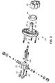
- FIG. 1 and Figure 2 show a rotary, swash plate pump 20 of the type used for marine steering systems, although the pump could be used for other purposes or adapted for other purposes.
- the pump includes a drive shaft 22.
- the steering wheel (not shown) is mounted on the shaft.
- the shaft in this example is fixedly mounted on an end cap 24.
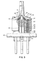
- the pump include a rotor 26 which has a first end 28 and a second end 30. There is a central bore 32 and a plurality of cylinder bores 34 which are arranged about the central bore and extend completely through the rotor from the first end 28 to the second end 30 as seen in Figure 3. There is a plurality of pistons 40, each being reciprocatingly received in one of the cylinder bores as seen in Figures 3 and 7. A passageway 41 extends through the rotor from each cylinder bore 34 to the central bore 32 of the rotor.
- a swash plate member 44 with a ball thrust bearing 46 there is a swash plate member 44 with a ball thrust bearing 46.
- a spigot 50 is rigidly connected to the center of the swash plate member and extends outwardly therefrom. The spigot extends through the central bore 32 of the rotor as shown in Figures 3 and 7.
- Each of the pistons has a rounded end 43 with slidingly engages the swash plate.
- End cap 24 is connected to the first end 28 of the rotor, by a plurality of Allen-head bolts 54 in this example.
- the bolts pass through apertures 56 in the end cap and are threadedly received in apertures 58 of the rotor. As may be seen in Figure 3 and 7. the end cap 24 closes off the cylinder bores at the first end of the rotor.
- Each of the cylinder bores 34 has an annular recess 60 adjacent the first end 28 of the rotor.
- An O-ring 62 is conceived within each recess and is compressed between the end cap 24 and the rotor 26 to hydraulically seal each cylinder bore between the rotor and the end cap.
- a bearing in this case a needle thrust bearing race 70, which is positioned against the end cap 24 as seen in Figure 3 and 7.
- annular recess 72 on the end of the end cap facing the rotor which receives the bearing.
- Spigot 50 has a narrower projection 76 which extends through the bearing and is rotatably supports the bearing.
- a cir-clip 80 is received on groove 82 on the end the spigot to secure the bearing, and therefore the router and end cap assembly, to the spigot in proper relationship.
- the pump has a cover 86. shown in Figure 1 and 7, which extends about the end cap 24 and the rotor.
- the cover is a hollow housing with an open end 88 and an opposite end 90 which is closed, apart from central aperture 92.
- the cover is of glass fiber reinforced polyamide, though other materials could be substituted.
- the drive shaft 22 extends through the central aperture and is sealed by a seal assembly 94 held in position by a washer 96.
- the washer is held in place by a plurality of screws 97. shown in Figure 1, extending through apertures 98 in the washer and apertures 100 in the cover.
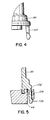
- a plurality of tabs 102 extend outwardly from the cover about the open end 88 as seen in Figure 1 and Figure 4
- the seal assembly 94 is shown in better detail.
- This includes an annular seal retainer 99 with an inwardly facing, annular channel 101.
- the retainer in this example is of rigid plastic and is of two components 103 and 105 which are connected together by welding in this embodiment.
- a resilient, annular seal 107. square in section in this example, is received within the channel 101.
- the retainer 99 is received within recess 109 on the cover.
- the recess is larger in diameter than the retainer 99. leaving a gap 111 which permits limited shifting of the seal assembly 94 relative to the cover.
- An O-ring 113 is received in an annular recess 115 formed in the cover and is compressed between the recess 115 in the cover and the retainer 99.
- the limited shifting of the seal assembly permitted by the gap 111 means that the drive shaft and the central aperture 92 in the cover do not have to be precisely machined because the retainer can shift relative to the housing so the seal 107 is tightly held against the drive shaft 22 to prevent leakage of fluid outwardly along the drive shaft. Leakage about the retainer 99 is prevented by the O-ring 113.
- Swash plate member 44 has a plurality of recesses 106 at shown in Figure 2. These correspond in number and position to the tabs 102 on the cover. As shown in Figure 5, the tabs 102 engage the recesses 106 to secure the cover to the swash plate member. Wedges 108 prevent disengagement of the tabs from the recesses.
- the cover 86 is not subject to high hydraulic pressure, nor does it physically take other significant stresses. Its function is chiefly as a protective cover and to prevent leakage of low-pressure hydraulic fluid. Accordingly, in this example, it is made of relatively lightweight plastic only. Other materials could be substituted, for example aluminum, other metals or composites. Also, because the cover is not subject to significant forces, it can be connected to the swash plate member by the tabs 102 which simply snap over the recesses 106. More significant connectors such as bolts are not required. Thus during assembly of the pump, the cover can simply be snapped in place by pushing it onto the swash plate member, saving in assembly time and cost compared to assemblies requiring bolts or other such fasteners.
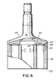
- the spigot 50 has a pair of longitudinal bores 120 and 122 extending therethrough. Slots 124 and 126 extend through the wall of the spigot from bores 120 and 122 respectively The slots align with the passageways 41 in the rotor, when the cylinder bores 34 arc rotated to a position in alignment with the slots, to permit fluid communication between the cylinder bores and the bores 120 and 122 in the spigot, the bores have inner ends 128 and 130 equipped with check valves 132 and 133. Each of the check valves includes a ball 136 biased against a passageway 138 by spring 140.
- a longitudinal member 141 extends through each of the passageways 120 and 122 to support the spring 140.
- the member is x-shaped in section although it could be tubular or another shape in alternative embodiments.
- a lock valve 150 is connected to the swash plate member 44 by a plurality of bolts 152 shown in Figure 2.
- a resilient seal 154 is received in recess 156 of the swash plate member as seen in Figure 7 and is compressed between the swash plate member and the valve by the bolts in this embodiment.
- a pair of O-rings 160 and 162 are compressed between the valve and the spigot about the passageways 120 and 122 respectively.
- the longitudinal members 141 extend from the springs 140 to the valve.
- the valve 150 is generally conventional in structure and includes a body 164 with a valve spool 166 reciprocatingly mounted in bore 168 thereof.
- the valve is generally conventional and similar to the valve disclosed in United States Patent No. 4.669.494 to McBeth and accordingly is described only briefly including the differences between this valve in the valve disclosed in McBeth.
- the spool has projections 170 and 172 on opposite ends thereof which can engage balls 180 and 182 of check valves 184 and 186. depending upon the position of the spool.
- Passageways 190 and 192 extend through the body and communicate with the bores 120 and 122 at one end and with the bore 168 as the opposite end.
- the valve 150 differs from the valve in United States Patent No. 4,669,494 in that it does not require a separate return port to allow fluid to flow to or from the tank passage.
- the valve body has an edge 171 adjacent the passageway 192 and the bore 166 as seen in Figure 9 When the edge 169 on land 167 of the spool clears edge 171 of the body as the Spool is shifted to the left from the point of view of Figure 9, returning fluid, indicated by arrows 177, can enter tank passageway 173. This removed the need for a separate return port for the tank passage and makes the valve easier and less expensive to manufacture.
- Passageways 200 and 202 extend from the check valves 184 and 186 to the swash plate member 44 where they communicate with passageways 204 and 206 which communicate with space 210 between the cover and the rotor.
- Each of the passageways 200 and 202 is provided with a check valve 220 which includes a ball 222 biased by a spring 224.
- the drive shaft 22 is rotated by the helm, depending upon the direction the boat is steered, this causes some of the pistons 40, for example piston 40.1 of Figure 7. to move upwardly, from the point of view or the drawing, as curved end 43 rides on the angled swash plate.
- the piston moves towards end cap 24 and pumps fluid through the passageway 41 and slot 126 into the longitudinal passageway 120.
- the pressurized fluid passes through passageway 190 in the valve 150 to communicate with the bore 168. This pressurized fluid unseats the ball 180 and allows the pressurized fluid to exit the valve through port 250 which is connected to the appropriate steering cylinder of the boat.
- the steering cylinder in some instances may be unbalanced. This occurs when the piston rod extends from its piston through one end of the cylinder only. Thus the effective areas of the piston are different on opposite sides. Therefore the volume of fluid flowing into one side is different from the volume flowing out of the opposite side.
- the invention is capable of accommodating this difference. If the volume of fluid returning to one of the cylinder bores 34 in the rotor is insufficient, then the appropriate ball 136 opens to admit fluid through passageway 138 from reservoir.
- the invention effectively eliminates leakage of fluid which has occurred with prior art devices.
- the cover 86 may he made of plastic, all of the high-pressure fluid from the pump may be confined within metallic parts including rotor 26, the spigot and the valve 150.
- the rotor in this example is of metal as are the pistons 34 so the fluid above the pistons is confined by the metal components.
- the fluid extends through the passageways 41 into the spigot which is also of metal.
- Within the spigot the fluid is confined within the bores 120 and 122.
- the outer end of the spigot is sealed against the body 164 of the valve which is also of metal.
- the high-pressure fluid within the valve is accordingly confined within metal components.
- Low-pressure fluid is confined within the system. It is located in the space 210 between the cover 84 and the rotor, within the passageways 128 and 130 as well as the cavities above and about the ball race 70. within the passageways 204 and 206 as well as the space between the swash plate and the spigot and the check valves below, between the pistons and the rotor and between the spigot and the rotor and swash plate member. Seal 154 prevents any leakage where the valve body is connected to the swash plate member. The only potential path for fluid to leak out of the pump, once the valve is attached, is along the drive shaft 22 about aperture 92. However this leakage is prevented by seal 99. This assumes a tight connection at port 250 together with the corresponding port on the other side of the valve. Unlike some prior art pumps of the type, there is no ready path for fluid to leak from the pump, for example between the spigot and the swash plate member.
Landscapes
- Engineering & Computer Science (AREA)
- Mechanical Engineering (AREA)
- General Engineering & Computer Science (AREA)
- Reciprocating Pumps (AREA)
- Eye Examination Apparatus (AREA)
- Details Of Reciprocating Pumps (AREA)
Applications Claiming Priority (2)
| Application Number | Priority Date | Filing Date | Title |
|---|---|---|---|
| US09/916,199 US6579072B2 (en) | 2001-07-27 | 2001-07-27 | Swash plate pump with low stress housing |
| EP01120932A EP1279830B1 (fr) | 2001-07-27 | 2001-08-31 | Pompe à plateau en biais |
Related Parent Applications (1)
| Application Number | Title | Priority Date | Filing Date |
|---|---|---|---|
| EP01120932A Division EP1279830B1 (fr) | 2001-07-27 | 2001-08-31 | Pompe à plateau en biais |
Publications (1)
| Publication Number | Publication Date |
|---|---|
| EP1818537A2 true EP1818537A2 (fr) | 2007-08-15 |
Family
ID=25436859
Family Applications (2)
| Application Number | Title | Priority Date | Filing Date |
|---|---|---|---|
| EP01120932A Expired - Lifetime EP1279830B1 (fr) | 2001-07-27 | 2001-08-31 | Pompe à plateau en biais |
| EP07109078A Withdrawn EP1818537A2 (fr) | 2001-07-27 | 2001-08-31 | Pompe à plateau en biais |
Family Applications Before (1)
| Application Number | Title | Priority Date | Filing Date |
|---|---|---|---|
| EP01120932A Expired - Lifetime EP1279830B1 (fr) | 2001-07-27 | 2001-08-31 | Pompe à plateau en biais |
Country Status (6)
| Country | Link |
|---|---|
| US (1) | US6579072B2 (fr) |
| EP (2) | EP1279830B1 (fr) |
| AT (1) | ATE363597T1 (fr) |
| AU (1) | AU783746B2 (fr) |
| CA (1) | CA2355911C (fr) |
| DE (1) | DE60128680T2 (fr) |
Families Citing this family (11)
| Publication number | Priority date | Publication date | Assignee | Title |
|---|---|---|---|---|
| US6692240B1 (en) * | 1999-11-29 | 2004-02-17 | Thomas Industries Inc. | Cylindrical pump housing with a fan guard mounted on each end of the housing with snap tabs engaging housing recesses |
| US20050220637A1 (en) * | 2004-04-01 | 2005-10-06 | Hydro-Gear Limited Partnership | Fan shroud for pump |
| DE102004052562B3 (de) * | 2004-10-29 | 2006-02-09 | Thyssen Krupp Automotive Ag | Kraftfahrzeuglenkung mit Überlagerungsgetriebe |
| WO2006130837A2 (fr) * | 2005-06-02 | 2006-12-07 | Kmt Waterjet Systems, Inc. | Pompe rotative haute pression |
| US8578838B2 (en) * | 2008-04-03 | 2013-11-12 | Marine Canada Acquisition Inc. | Lock valve with grooved porting in bore |
| US8534060B1 (en) | 2008-08-01 | 2013-09-17 | Hydro-Gear Limited Partnership | Drive device |
| US8984871B1 (en) | 2010-12-23 | 2015-03-24 | Hydro-Gear Limited Partnership | Transmission assembly |
| WO2017187228A1 (fr) * | 2016-04-27 | 2017-11-02 | Canada Metal (Pacific) Ltd. | Pompe hydraulique à commutateur isolé |
| US12326735B2 (en) | 2021-07-23 | 2025-06-10 | Seakeeper, Inc. | Dynamic active control system with engine control |
| WO2023023363A1 (fr) | 2021-08-19 | 2023-02-23 | Seakeeper, Inc. | Stratégie de mise en service |
| US12485998B2 (en) | 2021-08-23 | 2025-12-02 | Seakeeper, Inc. | Mounting plate assembly and system |
Family Cites Families (17)
| Publication number | Priority date | Publication date | Assignee | Title |
|---|---|---|---|---|
| GB1266155A (fr) | 1968-07-05 | 1972-03-08 | ||
| US4092905A (en) * | 1976-02-17 | 1978-06-06 | Teleflex Incorporated | Axial piston pump |
| US4211148A (en) | 1978-09-26 | 1980-07-08 | The United States Of America As Represented By The Secretary Of The Navy | Hot gas motor |
| JPS6165081A (ja) | 1984-09-05 | 1986-04-03 | Hitachi Ltd | 流体機械 |
| US4642032A (en) | 1985-08-07 | 1987-02-10 | Teleflex Incorporated | Axial piston pump including ball piston |
| US4669494A (en) | 1986-08-13 | 1987-06-02 | Teleflex Incorporated | Hydraulic lock valve with partial return to tank for marine steering |
| US4898077A (en) | 1988-09-06 | 1990-02-06 | Teleflex Incorporated | Self-bleeding hydraulic pumping apparatus |
| US5081908A (en) * | 1991-05-08 | 1992-01-21 | Teleflex Incorporated | Hydraulic pump having floating spigot valve |
| US5212995A (en) * | 1991-12-10 | 1993-05-25 | Robinson Melvin E | Profiler device |
| JPH06337072A (ja) * | 1993-05-28 | 1994-12-06 | Toyoda Gosei Co Ltd | 液圧ポンプ用メカニカルシール |
| US5349818A (en) | 1993-08-11 | 1994-09-27 | Teleflex (Canada) Limited | Low deadband marine hydraulic steering system |
| US5466130A (en) * | 1994-07-26 | 1995-11-14 | Kobelt; Jacob | Helm pump |
| IT1273698B (it) * | 1994-07-28 | 1997-07-09 | Dayco Europe Spa | Dispositivo di protezione per cuscinetti di pulegge in trasmissioni a cinghia |
| US5481871A (en) * | 1995-03-02 | 1996-01-09 | Teleflex (Canada) Ltd. | Hydraulic steering system with spool pressure equalization |
| US5655430A (en) * | 1995-06-26 | 1997-08-12 | Imo Industries, Inc. | Helm pump |
| US6055809A (en) * | 1998-02-10 | 2000-05-02 | Marol Kabushiki Kaisha | Remote steering system with a single rod cylinder and manual hydraulic piston pump for such a system |
| GB2326677A (en) | 1997-03-25 | 1998-12-30 | Lucas Ind Plc | Fuel pump |
-
2001
- 2001-07-27 US US09/916,199 patent/US6579072B2/en not_active Expired - Fee Related
- 2001-08-23 CA CA2355911A patent/CA2355911C/fr not_active Expired - Fee Related
- 2001-08-31 EP EP01120932A patent/EP1279830B1/fr not_active Expired - Lifetime
- 2001-08-31 DE DE60128680T patent/DE60128680T2/de not_active Expired - Lifetime
- 2001-08-31 EP EP07109078A patent/EP1818537A2/fr not_active Withdrawn
- 2001-08-31 AT AT01120932T patent/ATE363597T1/de not_active IP Right Cessation
-
2002
- 2002-06-20 AU AU48871/02A patent/AU783746B2/en not_active Ceased
Also Published As
| Publication number | Publication date |
|---|---|
| CA2355911A1 (fr) | 2003-01-27 |
| EP1279830A1 (fr) | 2003-01-29 |
| DE60128680T2 (de) | 2008-01-31 |
| AU4887102A (en) | 2003-01-30 |
| US20030021702A1 (en) | 2003-01-30 |
| DE60128680D1 (de) | 2007-07-12 |
| AU783746B2 (en) | 2005-12-01 |
| CA2355911C (fr) | 2005-05-24 |
| EP1279830B1 (fr) | 2007-05-30 |
| US6579072B2 (en) | 2003-06-17 |
| ATE363597T1 (de) | 2007-06-15 |
Similar Documents
| Publication | Publication Date | Title |
|---|---|---|
| US6579072B2 (en) | Swash plate pump with low stress housing | |
| USRE33135E (en) | Pump apparatus | |
| US11187214B2 (en) | Pump having a unitary body | |
| CA1056209A (fr) | Pompe a pistons axiaux | |
| CA1265976A (fr) | Pompe a piston axial, le piston etant de forme spherique | |
| HK1054583A (en) | Swash plate pump | |
| US5081908A (en) | Hydraulic pump having floating spigot valve | |
| US5638679A (en) | Hydraulic valve with dual-mode capability | |
| US4898077A (en) | Self-bleeding hydraulic pumping apparatus | |
| US3738228A (en) | Pump for hydraulic steering unit | |
| DE102006012986A1 (de) | Betätigungsvorrichtung | |
| US6273770B1 (en) | Hydraulic tilt system for marine propulsion | |
| US6446668B2 (en) | Multiway valve | |
| US5928041A (en) | Rotary valve actuated hydraulic steering system | |
| US20170298912A1 (en) | Hydrostatic pump barrel with sloped kidney ports | |
| US6487955B1 (en) | Piston structure of tilt apparatus for marine propulsion device | |
| US6500037B1 (en) | Servo steering mechanism for boats for example | |
| US7104613B2 (en) | Pump with reciprocating high pressure seal and valve for vehicle braking systems | |
| EP3515812B1 (fr) | Pompe de barre hydraulique dotée d'une pompe électrique intégrée | |
| US12448097B2 (en) | Balanced piston pump for subsea use | |
| US6662559B1 (en) | Hydraulic actuator | |
| US20080257432A1 (en) | Valve including a rotary spool and check valves | |
| WO2025068994A1 (fr) | Soupape de verrouillage et système de direction hydraulique comportant cette dernière | |
| AU2024350875A1 (en) | Lock valve and hydraulic steering system including same | |
| CA2405884C (fr) | Pompe bidirectionnelle pour l'entrainement de verins hydrauliques a piston unique a mouvement alternatif et rotatif simultanes |
Legal Events
| Date | Code | Title | Description |
|---|---|---|---|
| PUAI | Public reference made under article 153(3) epc to a published international application that has entered the european phase |
Free format text: ORIGINAL CODE: 0009012 |
|
| AC | Divisional application: reference to earlier application |
Ref document number: 1279830 Country of ref document: EP Kind code of ref document: P |
|
| AK | Designated contracting states |
Kind code of ref document: A2 Designated state(s): AT BE CH CY DE DK ES FI FR GB GR IE IT LI LU MC NL PT SE TR |
|
| RIN1 | Information on inventor provided before grant (corrected) |
Inventor name: TROUSIL, DANA Inventor name: KUYPER, JAN |
|
| STAA | Information on the status of an ep patent application or granted ep patent |
Free format text: STATUS: THE APPLICATION IS DEEMED TO BE WITHDRAWN |
|
| 18D | Application deemed to be withdrawn |
Effective date: 20120301 |