EP1819280B1 - Dispositif de tension de ligaments et gabarit de coupe pour procédé d'osteotomie - Google Patents
Dispositif de tension de ligaments et gabarit de coupe pour procédé d'osteotomie Download PDFInfo
- Publication number
- EP1819280B1 EP1819280B1 EP05797446.1A EP05797446A EP1819280B1 EP 1819280 B1 EP1819280 B1 EP 1819280B1 EP 05797446 A EP05797446 A EP 05797446A EP 1819280 B1 EP1819280 B1 EP 1819280B1
- Authority
- EP
- European Patent Office
- Prior art keywords
- ligament
- tensioning device
- medial
- lateral
- femur
- Prior art date
- Legal status (The legal status is an assumption and is not a legal conclusion. Google has not performed a legal analysis and makes no representation as to the accuracy of the status listed.)
- Ceased
Links
- 238000002271 resection Methods 0.000 claims description 31
- 210000000078 claw Anatomy 0.000 claims description 21
- 210000000988 bone and bone Anatomy 0.000 claims description 13
- 238000006073 displacement reaction Methods 0.000 claims description 9
- 238000005553 drilling Methods 0.000 claims description 9
- 238000002360 preparation method Methods 0.000 claims description 8
- 239000007943 implant Substances 0.000 claims description 5
- 238000002513 implantation Methods 0.000 claims description 2
- 230000000284 resting effect Effects 0.000 claims 2
- 210000000689 upper leg Anatomy 0.000 description 35
- 210000000629 knee joint Anatomy 0.000 description 15
- 210000002303 tibia Anatomy 0.000 description 6
- 210000003041 ligament Anatomy 0.000 description 5
- 238000000034 method Methods 0.000 description 5
- 238000003780 insertion Methods 0.000 description 4
- 230000037431 insertion Effects 0.000 description 4
- 238000011065 in-situ storage Methods 0.000 description 3
- 230000007480 spreading Effects 0.000 description 3
- 241001465754 Metazoa Species 0.000 description 2
- 238000013459 approach Methods 0.000 description 2
- 238000011066 ex-situ storage Methods 0.000 description 2
- 238000005259 measurement Methods 0.000 description 2
- 238000012545 processing Methods 0.000 description 2
- 230000008901 benefit Effects 0.000 description 1
- 238000006243 chemical reaction Methods 0.000 description 1
- 230000000694 effects Effects 0.000 description 1
- 238000010348 incorporation Methods 0.000 description 1
- 210000003127 knee Anatomy 0.000 description 1
- 239000003550 marker Substances 0.000 description 1
- 230000007246 mechanism Effects 0.000 description 1
- 230000008569 process Effects 0.000 description 1
- 230000003252 repetitive effect Effects 0.000 description 1
- 230000007704 transition Effects 0.000 description 1
Images



Classifications
-
- A—HUMAN NECESSITIES
- A61—MEDICAL OR VETERINARY SCIENCE; HYGIENE
- A61B—DIAGNOSIS; SURGERY; IDENTIFICATION
- A61B17/00—Surgical instruments, devices or methods
- A61B17/14—Surgical saws
- A61B17/15—Guides therefor
- A61B17/154—Guides therefor for preparing bone for knee prosthesis
- A61B17/155—Cutting femur
-
- A—HUMAN NECESSITIES
- A61—MEDICAL OR VETERINARY SCIENCE; HYGIENE
- A61B—DIAGNOSIS; SURGERY; IDENTIFICATION
- A61B17/00—Surgical instruments, devices or methods
- A61B17/02—Surgical instruments, devices or methods for holding wounds open, e.g. retractors; Tractors
- A61B17/025—Joint distractors
-
- A—HUMAN NECESSITIES
- A61—MEDICAL OR VETERINARY SCIENCE; HYGIENE
- A61B—DIAGNOSIS; SURGERY; IDENTIFICATION
- A61B17/00—Surgical instruments, devices or methods
- A61B17/16—Instruments for performing osteoclasis; Drills or chisels for bones; Trepans
- A61B17/17—Guides or aligning means for drills, mills, pins or wires
- A61B17/1732—Guides or aligning means for drills, mills, pins or wires for bone breaking devices
-
- A—HUMAN NECESSITIES
- A61—MEDICAL OR VETERINARY SCIENCE; HYGIENE
- A61B—DIAGNOSIS; SURGERY; IDENTIFICATION
- A61B17/00—Surgical instruments, devices or methods
- A61B17/16—Instruments for performing osteoclasis; Drills or chisels for bones; Trepans
- A61B17/17—Guides or aligning means for drills, mills, pins or wires
- A61B17/1739—Guides or aligning means for drills, mills, pins or wires specially adapted for particular parts of the body
- A61B17/1764—Guides or aligning means for drills, mills, pins or wires specially adapted for particular parts of the body for the knee
-
- A—HUMAN NECESSITIES
- A61—MEDICAL OR VETERINARY SCIENCE; HYGIENE
- A61B—DIAGNOSIS; SURGERY; IDENTIFICATION
- A61B17/00—Surgical instruments, devices or methods
- A61B17/02—Surgical instruments, devices or methods for holding wounds open, e.g. retractors; Tractors
- A61B17/025—Joint distractors
- A61B2017/0268—Joint distractors for the knee
-
- A—HUMAN NECESSITIES
- A61—MEDICAL OR VETERINARY SCIENCE; HYGIENE
- A61B—DIAGNOSIS; SURGERY; IDENTIFICATION
- A61B90/00—Instruments, implements or accessories specially adapted for surgery or diagnosis and not covered by any of the groups A61B1/00 - A61B50/00, e.g. for luxation treatment or for protecting wound edges
- A61B90/06—Measuring instruments not otherwise provided for
- A61B2090/061—Measuring instruments not otherwise provided for for measuring dimensions, e.g. length
-
- A—HUMAN NECESSITIES
- A61—MEDICAL OR VETERINARY SCIENCE; HYGIENE
- A61B—DIAGNOSIS; SURGERY; IDENTIFICATION
- A61B90/00—Instruments, implements or accessories specially adapted for surgery or diagnosis and not covered by any of the groups A61B1/00 - A61B50/00, e.g. for luxation treatment or for protecting wound edges
- A61B90/06—Measuring instruments not otherwise provided for
- A61B2090/064—Measuring instruments not otherwise provided for for measuring force, pressure or mechanical tension
Definitions
- the invention relates to a ligament-tensioning device for joints of the human or animal body. Also disclosed is a cutting jig suitable for use on a joint prepared by means of the ligament-tensioning device and a method for osteotomy of these joints using the ligament-tensioning device of the invention and the cutting jig.
- a ligament-tensioning device in preparation for the implantation of a joint implant having a base body, which has a first claw with a distal contact surface, which rests on a first bone, and a second claw, which rests with a proximal bearing surface on a second bone.
- the second claw is displaceable parallel to the first claw.
- a cutting gauge can be placed on holders of the main body of the ligament-tensioning device.
- the device described therein for tensioning ligaments on non-spherical joints on the human or animal body comprises a prismatic, cylindrical or plate-shaped base body with a right claw and a left claw, which first bearing surfaces in a plane and thus parallel to the joint-side surface of a first right hand grip and a left hand grip, a right cocking lever and a left cocking lever with second bearing surfaces, which are arranged parallel to the first bearing surfaces, wherein between the respective bearing surfaces of the right Tension levers and the right claw a span Y and between the respective bearing surfaces of the left clamping lever and the left claw the same or another span X is adjustable.
- the second bearing surface can be brought to bear against the joint-side surface of a second bone adjacent to the joint.
- the apparatus comprises a right operating lever and a left operating lever, which are operable simultaneously with the holding of the device with one hand on the corresponding handle individually with the same hand and a right parallel displacement device and a left parallel displacement device, each driven by the corresponding operating lever are and are thus connected to a respective clamping lever, that during a movement of the operating lever, the spans X and Y are independently adjustable.
- the Parallelverschiebevoriquesen are designed as four-bar lever mechanism.
- ligament-tensioning devices known from the above-mentioned publications is, in particular, that the attachment of cutting planes to a diseased joint for the introduction of a prosthesis requires further tools which are attached to the joint independently of the tensioning device and therefore no exact positioning and alignment and no reproducible allow accurate cutting.
- the invention is therefore an object of the invention to provide a ligament-tensioning device to clamp the capsular ligament structures of a prosthetic joint to be supplied with a parallel expansion movement while a presettable, readjustable and nachkontrollierbare Resetations us for the medial and the lateral side are separated from each other adjustable.
- Fig. 1A shows in a schematic, perspective overall view of a ligament-tensioning device 1, which comprises a base body 5, on which a guide body 3 is arranged with guide rods 4.
- a ligament-tensioning device 1 which comprises a base body 5, on which a guide body 3 is arranged with guide rods 4.
- On the guide rods 4 are different jigs 2 for the preparation of resections in the range of a prosthetic to be supplied joint, such as a knee joint, attachable and movable.
- the ligament-tensioning device 1 comprises, for safe introduction of the spreading force into a first bone part 33, first claws 6, 6 '(in FIG Fig. 1A not visible) with first bearing surfaces 7, 7 '(in Fig. 1A also not visible), which in case of the knee joint rest on the tibia 33 (tibial head).
- the first claws 6, 6 'opposite corresponding to the main body 5 handles 8, 8' are mounted, which each allow a one-handed holding and tensioning the ligament-tensioning device 1.
- the ligament-tensioning device 1 comprises clamping levers 9, 9', which coincide with their on second claws 13, 13 '(in Fig.
- the four levers 14, 15, 16, 17 and 14 ', 15', 16 ', 17' are each by means of five axes 18, 19, 20, 21, 22 and 18 ', 19', 20 ', 21st ', 22' connected.
- the lengths of the levers 14, 14 '15, 15', 16, 16 ', 17, 17' are chosen so that at an arbitrary span X between the bearing surfaces 7, 7 'on the first claws 6, 6' and the bearing surfaces 10, 10 'on the second claws 13, 13', which, for example may be between 5 mm and 40 mm, a constant conversion ratio of 1: 1 between the manually applied to the handles 8, 8 'and the operating levers 11, 11' applied clamping force and exerted on the bone adjacent to the joint distraction force.
- the size of the spreading force is on force indicators 25, 25 'with scales 26, 26' and movable indicator levers 27, 27 'read.
- the indicator levers 27, 27 ' are characterized by the longitudinal deflection of a manually applied Clamping force bendable operating lever parts 28, 28 'relative to the other fork-like arranged and not acted upon by this clamping force indicator levers 27, 27' moves. Be by means of the clamping force of the indicator lever 27, 27 'and the operating lever parts 28, 28' moves relative to each other, rotate the display lever 27, 27 'about axes of rotation 29, 29', which on the scales 26, 26 'by the indicator lever 27, 27th 'the manually applied clamping force is displayed.
- the main body 5 of the ligament-tensioning device 1 has a first scale 31, which corresponds to second scales 32, 32 '.
- the scales 31, 32 and 32 '(in Fig. 1A also not visible) indicate the planned resection height medially and laterally on the bone, eg at the femur 34, taking into account the ligamentous situation and with already resected tibia 33, whereby the resection heights can be measured medially and laterally before the resection, dorsally and ventrally.
- By choosing the femoral resection height optimal reproduction of the physiological joint plane is possible.
- the exact function of the ligament-tensioning device 1 is explained in more detail in the following figures and in the associated description.
- Fig. 1B shows in a schematic view with a view towards the dorsal a plan view of the Ligament-tensioning device 1.
- the scales 31 and 32, 32 ' can be seen, which, as already mentioned, indicate the planned resection heights medially and laterally on the femur 34 taking into account the ligamentous situation and allow a measurement of the resection heights medially and laterally to obtain the correct resection heights perpendicular to, ie dorsal and ventral, to determine.
- an optimal reproduction of the physiological joint plane is possible, since both the mediallateral direction and the dorsal-ventral direction enter into the measurement and thus in the cut of the resection.
- the scales 31 and 32 and 31 and 32 ' correspond to each other. Since the ligament-tensioning device 1 is equipped with two independently operating parallel displacement devices 12, 12 ', which can be actuated independently of one another, different widths of the knee joint gap or inlay can thus be adjusted medially and laterally, so that the ligamentous situation of the joint can be optimally taken into account ,
- a joint prosthesis consists of several components, which are used depending on the state of the joint in one or both bone parts 33, 34.
- an endoprosthesis is necessary, which may additionally comprise an inlay which lies between the prosthesis parts and, in the case of the knee joint, takes over the function of the menisci. It is important for satisfactory care of the patient to correctly determine the height of the inlay and preparing the resection height of the involved bones 33, 34.
- Fig. 1C is in a side view the situation according to Fig. 1A and 1B shown.
- the drill guide 2 is already in abutment with the femur 34.
- By means of a drill two holes are introduced into the femur 34, which, as described below, record a cutting jig.
- the tibia 33 is prepared by conventional resection methods, so that a transverse surface 36 is formed, against which the claws 6, 6 'of the ligament-tensioning device 1.
- the ligament-tensioning device 1 is inserted into the knee joint gap between the tibia 33 and the femur 34.
- the drilling jig 2 for the introduction of the holes for the cutting jig, which for a first, distal femoral resection is used is already placed on the ligament-tensioning device 1.
- the ligament-tensioning device 1 by operating the ligament-tensioning device 1 in the extension position, the ligaments are spread open under a selectable force.
- the force is read and set on the scales 26, 26 'of the force indicators 25, 25'.
- the values read on the scales 31, 32, 32 ' give the resection height of the first, distal femoral resection or the thickness of the inlays to be inserted later between the prosthesis components. Due to the separate adjustability for the medial and the lateral side, different values can result on the scales 32, 32 ', which correspond to a rotation of the femur 34. Per millimeter of the scales 32, 32 ', the rotation is preferably 1 °.
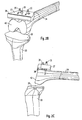
- FIG. 2A to 2C In various views, the attachment of the cutting template 37 required for the distal femoral resection is shown.
- the joint becomes, as from the Fig. 2A to 2C can be seen flexed in flexion, so bent, and the cutting guide 37 attached to the pins 35. So that the cutting guide 37 can not move, it is fixed by means of a fixation nail 39 on the femur 34.
- the cutting gauge 37 has a saw blade guide 38 through which a saw blade is guided during the resection.
- a transversely oriented surface 40 has also been formed on the femur 34, which is oriented in extension parallel to the transverse surface 36 of the tibia 33.
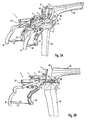
- the ligament-tensioning device 1 becomes, as in Fig. 3A shown in a perspective overall view, again attached to the still in flexion located joint.
- the drilling jig 2 is replaced by a second drilling jig 41, which is mounted on the ligament-tensioning device 1 in the same way as the jig 2.
- Fig. 3B and 3C show in a side view the drill guide 41 in the preassembled state or after the abutment against the transverse surface 40 of the femur 34.
- the flexion of the knee joint is corrected so that the drill guide 41 and the surface 40 over the entire surface in abutment with each other can be brought. This is important to ensure proper positioning of the holes.
- the drilling jig 41 has two guides 42 for the drill and a push-in bore 43 into which a feeler gauge 44 for determining the femur size can be inserted in the next method step.
- Fig. 3D shows the repeated control of the resection height on the basis of the scales 31, 32, 32 'before determining the size of the femur by means of the feeler gauge 44 to ensure that the correct cutting gauge for the second femur resection is selected later.
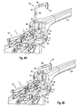
- FIGS. 4A to 4C the determination of the femur size is shown by scanning by means of a caliper gauge 44.
- the caliper 44 has an L-shaped bracket 45 with a scale 46 which is formed on the part of the bracket 45 which is inserted into the insertion hole 43 of the jig 41.
- the length of the bracket 45 in the proximal-distal direction is variable via a displacement device 48.
- the femur size is determined, which can be read on the scale 46.
- the scale 46 has five markers A, B, C, D and E, which correspond to five different femur sizes, A being the smallest and E the largest size.
- the number of markings is not limited to five, it may also be more or less or have other distances between the markers.
- the femur size has been determined with marker B. This is the mark which is still visible above the insertion hole 43 in the drilling jig 44.
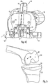
- FIG. 5 shows the situation after the introduction of the holes 49 and after removal of the ligament-tensioning device 1 in flexion. In the surface 40, the two holes 49 are introduced, the transversely oriented surfaces 36 and 40 are in extension of the knee joint then parallel to each other.
- FIG. 2 shows the starting situation for the last processing step of preparation for the implant supply, namely for the ventral and dorsal resections of the femur 34.
- the cutting gauge 50 is matched to the size of the femur 34 previously determined using the caliper gauge 44, ie, a separate cutting gauge 50 is provided for each of the femur sizes A, B, C, D, E indicated on the scale 46, wherein the cutting gauges 50 different for the different femoral sizes in their dimensions.
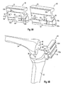
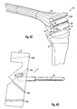
- Fig. 6A For example, the cutting gauges 50 for a size A small femur 34 (left in FIG Fig. 6A ) and for a large femur 34 of size E (right in Fig. 6A ) to illustrate the differences.
- the cutting gauge 50 consists of a cutting block 51 which has two pins 52 for insertion into the bores 49 previously introduced into the transverse surface 40 of the femur 34.
- the pins 52 are arranged approximately in the direction of a surface normal on the cutting block 51.
- the cutting block 51 further comprises saw blade guides 53 which are formed at different angles in the cutting block 51.
- the number of saw blade guides 53 is four, which are applied for each of a dorsal femoral cut, a dorsal oblique cut, a ventral oblique cut and a ventral femoral cut.
- the cutting block 51 is designed so that a distance X between a first saw blade guide 53 a for a dorsal femoral cut, which in FIGS. 6A to 6D each is the lowest (dorsal) saw blade guide 53, and the pins 52 for all femoral sizes A, B, C, D, E is the same size.
- This has the advantage that the dorsal femoral cut always takes place in the same place and thus later the endoprosthesis relative to the femur 34 can always be properly positioned.
- the saw blade guide 53a for the dorsal femoral cut is designed in two parts, wherein the two partial slots are separated by a web 54. This is appropriate to increase the stability of the cutting block 51.
- the next succeeding saw blade guide 53b is arranged inclined to the first saw blade guide 53a for a dorsal oblique cut.
- the saw blade guide 53 b for the dorsal oblique cut is also formed in two parts and divided by the web 54.
- Another saw blade guide 53c for a ventral oblique cut is designed in the form of a completely closed slot and inclined relative to the saw blade guide 53b to be used for the dorsal bevel cut by approximately 90 °.
- a fourth saw blade guide 53d is also completely closed and to be used for the implementation of the final ventral femoral cut.
- Fig. 6D shows in a side view a cutting jig 50, in which the two saw blade guides 53a and 53b are visible from the side, while the two ventral saw blade guides 53c and 53d in Fig. 6D only visible in the projection, as they are designed as completely closed slots.
- two holes 56 are formed in the cutting block 51 in the example, which serve to fix the cutting block 51 on the femur 34. Through the holes 56 Fixation nails can be taken in the transverse surface 40 of the femur 34. This ensures that the cutting jig 50 does not shift during the four resection cuts.
- Fig. 6B and 6C show the preparation of the cutting jig 50 to the still in flexion knee joint or the cutting jig 50 in situ.
- the invention is not limited to the illustrated embodiment, but also applicable to ligament-tensioning devices 1 for other spherical joints with appropriate adjustment.
Landscapes
- Health & Medical Sciences (AREA)
- Life Sciences & Earth Sciences (AREA)
- Surgery (AREA)
- General Health & Medical Sciences (AREA)
- Veterinary Medicine (AREA)
- Biomedical Technology (AREA)
- Heart & Thoracic Surgery (AREA)
- Medical Informatics (AREA)
- Molecular Biology (AREA)
- Animal Behavior & Ethology (AREA)
- Nuclear Medicine, Radiotherapy & Molecular Imaging (AREA)
- Public Health (AREA)
- Engineering & Computer Science (AREA)
- Orthopedic Medicine & Surgery (AREA)
- Dentistry (AREA)
- Oral & Maxillofacial Surgery (AREA)
- Physical Education & Sports Medicine (AREA)
- Transplantation (AREA)
- Surgical Instruments (AREA)
- Prostheses (AREA)
Claims (7)
- Dispositif de tension de ligaments (1) pour la préparation à l'implantation d'un implant articulaire doté d'un corps de base (5) qui présente des premières pattes (6, 6') comportant des premières surfaces d'appui médiale et latérale (7, 7') qui reposent sur une première partie osseuse (33) et des deuxièmes pattes (13, 13') comportant des deuxièmes surfaces d'appui médiale et latérale (10, 10') sur une deuxième partie osseuse (34), les pattes médiale et latérale respectives (6, 6', 13, 13') pouvant être décalées les unes par rapport aux autres par un dispositif de décalage parallèle médial et latéral (12, 12') et comportant une première échelle (31) qui est disposée sur le corps de base (5) du dispositif de tension de ligaments (1), des deuxièmes échelles médiale et latérale (32, 32') étant prévues, dans lequel à l'aide de l'échelle médiale (32), une hauteur de résection médiale prévue peut être mesurée et à l'aide de l'échelle latérale (32'), une hauteur de résection latérale prévue peut être mesurée,
caractérisé en ce que
les deuxièmes échelles (32, 32') sont disposées sur un corps de guidage (3) qui est placé de façon à pouvoir coulisser de l'autre côté du corps de base (5), la hauteur d'un implant à insérer dans l'articulation pouvant être prédéfinie par décalage du corps de guidage (3) au moyen de la première échelle (31). - Dispositif de tension de ligaments selon la revendication 1,
caractérisé en ce que
les deuxièmes échelles (32, 32') sont disposées sur les côtés médial et latéral du corps de guidage (3). - Dispositif de tension de ligaments selon la revendication 1 ou 2,
caractérisé en ce que
dans le corps de guidage (3) sont formées des tiges de guidage (4). - Dispositif de tension de ligaments selon la revendication 3,
caractérisé en ce que
les tiges de guidage (4) ont une orientation ventrale - dorsale. - Dispositif de tension de ligaments selon la revendication 3 ou 4,
caractérisé en ce que
les tiges de guidage (4) peuvent être décalées dans une direction ventrale - dorsale dans le corps de guidage (3). - Dispositif de tension de ligaments selon l'une des revendications 3 à 5,
caractérisé en ce que
sur les tiges de guidage (4), des gabarits d'alésage (2, 41) peuvent être placés. - Dispositif de tension de ligaments selon la revendication 6,
caractérisé en ce que
une position des gabarits d'alésage (2, 41) peut varier en deux degrés de liberté par rapport à la deuxième partie osseuse (34) par le biais du dispositif de tension de ligaments (1) et des tiges de guidage.
Applications Claiming Priority (2)
| Application Number | Priority Date | Filing Date | Title |
|---|---|---|---|
| DE102004050913A DE102004050913A1 (de) | 2004-10-19 | 2004-10-19 | Bänderspannvorrichtung, Schnittlehre und Verfahren zur Osteotomie |
| PCT/EP2005/011203 WO2006042743A2 (fr) | 2004-10-19 | 2005-10-18 | Dispositif de tension de ligaments, gabarit de coupe et procede d'osteotomie |
Publications (2)
| Publication Number | Publication Date |
|---|---|
| EP1819280A2 EP1819280A2 (fr) | 2007-08-22 |
| EP1819280B1 true EP1819280B1 (fr) | 2013-08-14 |
Family
ID=35589284
Family Applications (1)
| Application Number | Title | Priority Date | Filing Date |
|---|---|---|---|
| EP05797446.1A Ceased EP1819280B1 (fr) | 2004-10-19 | 2005-10-18 | Dispositif de tension de ligaments et gabarit de coupe pour procédé d'osteotomie |
Country Status (5)
| Country | Link |
|---|---|
| US (1) | US20070293868A1 (fr) |
| EP (1) | EP1819280B1 (fr) |
| AU (1) | AU2005296761B2 (fr) |
| DE (1) | DE102004063977A1 (fr) |
| WO (1) | WO2006042743A2 (fr) |
Families Citing this family (68)
| Publication number | Priority date | Publication date | Assignee | Title |
|---|---|---|---|---|
| US7534263B2 (en) | 2001-05-25 | 2009-05-19 | Conformis, Inc. | Surgical tools facilitating increased accuracy, speed and simplicity in performing joint arthroplasty |
| US7468075B2 (en) | 2001-05-25 | 2008-12-23 | Conformis, Inc. | Methods and compositions for articular repair |
| US8083745B2 (en) | 2001-05-25 | 2011-12-27 | Conformis, Inc. | Surgical tools for arthroplasty |
| AU772012B2 (en) | 1998-09-14 | 2004-04-08 | Board Of Trustees Of The Leland Stanford Junior University | Assessing the condition of a joint and preventing damage |
| US7239908B1 (en) | 1998-09-14 | 2007-07-03 | The Board Of Trustees Of The Leland Stanford Junior University | Assessing the condition of a joint and devising treatment |
| AU2001290888B8 (en) | 2000-09-14 | 2007-07-26 | The Board Of Trustees Of The Leland Stanford Junior University | Assessing the condition of a joint and devising treatment |
| WO2002022013A1 (fr) | 2000-09-14 | 2002-03-21 | The Board Of Trustees Of The Leland Stanford Junior University | Evaluation de l'etat d'une articulation et d'une perte de cartilage |
| US8439926B2 (en) | 2001-05-25 | 2013-05-14 | Conformis, Inc. | Patient selectable joint arthroplasty devices and surgical tools |
| US20190038298A1 (en) * | 2001-05-25 | 2019-02-07 | Conformis, Inc. | Patient Selectable Joint Arthroplasty Devices and Surgical Tools |
| US20170164957A1 (en) * | 2001-05-25 | 2017-06-15 | Conformis, Inc. | Patient Selectable Joint Arthroplasty Devices and Surgical Tools |
| CN100502808C (zh) | 2001-05-25 | 2009-06-24 | 肯弗默斯股份有限公司 | 用于关节表面再造的组合物 |
| US8317797B2 (en) | 2005-02-08 | 2012-11-27 | Rasmussen G Lynn | Arthroplasty systems and methods for optimally aligning and tensioning a knee prosthesis |
| US12575818B2 (en) | 2005-02-08 | 2026-03-17 | G. Lynn Rasmussen | Arthroplasty systems and methods for optimally aligning and tensioning a knee prosthesis |
| US8303597B2 (en) * | 2005-02-08 | 2012-11-06 | Rasmussen G Lynn | Systems and methods for guiding cuts to a femur and tibia during a knee arthroplasty |
| US7927336B2 (en) * | 2005-02-08 | 2011-04-19 | Rasmussen G Lynn | Guide assembly for guiding cuts to a femur and tibia during a knee arthroplasty |
| GB0526385D0 (en) * | 2005-12-28 | 2006-02-08 | Mcminn Derek J W | Improvements in or relating to knee prosthesis |
| EP2671521A3 (fr) | 2006-02-06 | 2013-12-25 | ConforMIS, Inc. | Dispositifs d'arthroplastie articulaire et outils chirurgicaux selectionnables par le patient |
| US8623026B2 (en) | 2006-02-06 | 2014-01-07 | Conformis, Inc. | Patient selectable joint arthroplasty devices and surgical tools incorporating anatomical relief |
| DE102006050311A1 (de) * | 2006-10-25 | 2008-04-30 | Brehm, Peter | Schablone zum Durchführen einer Umstellungsosteotomie |
| GB2447702A (en) | 2007-03-23 | 2008-09-24 | Univ Leeds | Surgical bone cutting template |
| WO2008157412A2 (fr) | 2007-06-13 | 2008-12-24 | Conformis, Inc. | Guide d'incision chirurgical |
| EP2265199A4 (fr) * | 2008-03-05 | 2012-03-07 | Conformis Inc | Dispositifs d arthroplastie articulaire sélectionnable par le patient et outils chirurgicaux |
| FR2935092B1 (fr) * | 2008-08-25 | 2011-12-16 | Francis Guillaume | Ensemble d'ancillaires pour implanter une prothese de genou. |
| US9017334B2 (en) | 2009-02-24 | 2015-04-28 | Microport Orthopedics Holdings Inc. | Patient specific surgical guide locator and mount |
| US8808303B2 (en) | 2009-02-24 | 2014-08-19 | Microport Orthopedics Holdings Inc. | Orthopedic surgical guide |
| US8808297B2 (en) | 2009-02-24 | 2014-08-19 | Microport Orthopedics Holdings Inc. | Orthopedic surgical guide |
| US12383287B2 (en) | 2009-02-24 | 2025-08-12 | Microport Orthopedics Holdings, Inc. | Systems and methods for installing an orthopedic implant |
| US8721568B2 (en) | 2009-03-31 | 2014-05-13 | Depuy (Ireland) | Method for performing an orthopaedic surgical procedure |
| US8551023B2 (en) * | 2009-03-31 | 2013-10-08 | Depuy (Ireland) | Device and method for determining force of a knee joint |
| CN102448394B (zh) | 2009-04-16 | 2015-07-22 | 康复米斯公司 | 用于韧带修复的患者专属关节成形术装置 |
| FR2948274B1 (fr) * | 2009-07-24 | 2011-09-16 | Tornier Sa | Instrumentation chirurgicale pour la preparation a la pose d'une prothese de genou |
| CA2778040A1 (fr) * | 2009-10-23 | 2011-04-28 | Synvasive Technology, Inc. | Equilibrage de genou pour des interventions de revision |
| GB2475491A (en) * | 2009-11-18 | 2011-05-25 | Biomet Uk Ltd | Alignment tool for a femoral drill guide |
| DE102010013259A1 (de) | 2009-12-23 | 2011-06-30 | Mathys Ag Bettlach | Femur-Schnittführungsvorrichtung für Revisionsoperationen in der Knie-Endoprothetik |
| US8556901B2 (en) | 2009-12-31 | 2013-10-15 | DePuy Synthes Products, LLC | Reciprocating rasps for use in an orthopaedic surgical procedure |
| US8506569B2 (en) | 2009-12-31 | 2013-08-13 | DePuy Synthes Products, LLC | Reciprocating rasps for use in an orthopaedic surgical procedure |
| GB2479899A (en) * | 2010-04-28 | 2011-11-02 | Biomet Uk Ltd | Alignment tool for use in joint replacement |
| US8974459B1 (en) | 2010-05-21 | 2015-03-10 | Howmedica Osteonics Corp. | Natural alignment knee instruments |
| JP5572491B2 (ja) * | 2010-09-13 | 2014-08-13 | 竜沢 金山 | 人工膝関節置換手術時に使用される骨切除治具 |
| US8486076B2 (en) | 2011-01-28 | 2013-07-16 | DePuy Synthes Products, LLC | Oscillating rasp for use in an orthopaedic surgical procedure |
| US10166034B2 (en) * | 2011-07-19 | 2019-01-01 | Zimmer, Inc. | Knee arthroplasty instrument |
| FR2979222B1 (fr) * | 2011-08-29 | 2014-06-06 | I M A G E | Guide de forage |
| WO2013063043A1 (fr) | 2011-10-24 | 2013-05-02 | Synvasive Technology, Inc. | Dispositifs, systèmes et procédés d'équilibrage du genou |
| US9381011B2 (en) | 2012-03-29 | 2016-07-05 | Depuy (Ireland) | Orthopedic surgical instrument for knee surgery |
| US9486226B2 (en) | 2012-04-18 | 2016-11-08 | Conformis, Inc. | Tibial guides, tools, and techniques for resecting the tibial plateau |
| US9675471B2 (en) | 2012-06-11 | 2017-06-13 | Conformis, Inc. | Devices, techniques and methods for assessing joint spacing, balancing soft tissues and obtaining desired kinematics for joint implant components |
| GB2526722B (en) * | 2013-05-23 | 2018-02-28 | Moholkar Kirti | Femoral block for use in knee replacement surgery |
| WO2014188184A1 (fr) * | 2013-05-23 | 2014-11-27 | Kirti Moholkar | Améliorations apportées à des ensembles destinés à être utilisés dans l'arthroplastie du genou |
| WO2016081094A1 (fr) | 2014-11-19 | 2016-05-26 | Zimmer, Inc. | Dispositif de calibrage fémoral de référencement d'espace |
| DE102016204307B3 (de) * | 2016-03-16 | 2017-07-20 | Carsten Boos | Operationsvorrichtung für eine Operation des menschlichen Knies |
| US11992230B2 (en) | 2016-11-30 | 2024-05-28 | G. Lynn Rasmussen | Systems and methods for providing a tibial baseplate |
| US12414862B2 (en) | 2016-11-30 | 2025-09-16 | G. Lynn Rasmussen | Systems and methods for providing a tibial baseplate system |
| US11284873B2 (en) | 2016-12-22 | 2022-03-29 | Orthosensor Inc. | Surgical tensor where each distraction mechanism is supported and aligned by at least two guide shafts |
| US11266512B2 (en) | 2016-12-22 | 2022-03-08 | Orthosensor Inc. | Surgical apparatus to support installation of a prosthetic component and method therefore |
| US11291437B2 (en) | 2016-12-22 | 2022-04-05 | Orthosensor Inc. | Tilting surgical tensor to support at least one bone cut |
| US11185425B2 (en) | 2016-12-22 | 2021-11-30 | Orthosensor Inc. | Surgical tensor configured to distribute loading through at least two pivot points |
| US11399818B2 (en) * | 2016-12-22 | 2022-08-02 | Orthosensor Inc. | Surgical apparatus to support installation of a prosthetic component with reduced alignment error |
| FR3071147B1 (fr) * | 2017-09-18 | 2021-02-26 | Aston Medical | Dispositif d'aide a la pose d'une prothese de genou, outil distracteur et equilibreur du systeme ligamentaire du genou |
| AU2020283377B2 (en) | 2019-05-29 | 2022-08-04 | Wright Medical Technology, Inc. | Preparing a tibia for receiving tibial implant component of a replacement ankle |
| WO2021146015A1 (fr) | 2020-01-17 | 2021-07-22 | Wright Medical Technology, Inc. | Outils, systèmes et procédés de guidage |
| US20210228377A1 (en) | 2020-01-29 | 2021-07-29 | Howmedica Osteonics Corp. | Load Sensor Balancer Instruments |
| GB2598580A (en) * | 2020-09-02 | 2022-03-09 | James Hamilton Murray Brown | Knee replacement bone preparation guide |
| WO2022182430A1 (fr) | 2021-02-24 | 2022-09-01 | Wright Medical Technology, Inc. | Préparation d'un tibia pour la réception d'un composant d'implant tibial d'une cheville de remplacement |
| US12582421B2 (en) | 2022-05-13 | 2026-03-24 | Wright Medical Technology, Inc. | Intraoperative adjustable guides, systems, and methods |
| CN116473620B (zh) * | 2023-04-25 | 2025-01-21 | 江苏世康启航医疗器械有限公司 | 单髁置换截骨导向定位模块及单髁置换截骨导向定位系统 |
| US12569355B2 (en) | 2023-08-31 | 2026-03-10 | Wright Medical Technology, Inc. | Systems and methods for total ankle arthroplasty |
| CN117481740A (zh) * | 2023-10-19 | 2024-02-02 | 爱乔(上海)医疗科技有限公司 | 截骨定位装置 |
| CN119498925B (zh) * | 2025-01-17 | 2025-05-06 | 四川大学华西医院 | 一种股骨外旋截骨定位装置及其使用方法 |
Family Cites Families (8)
| Publication number | Priority date | Publication date | Assignee | Title |
|---|---|---|---|---|
| IT1248971B (it) * | 1990-06-22 | 1995-02-11 | Cremascoli G Srl | Apparecchiatura atta a consentire l'esecuzione di una corretta resezione femorale e tibiale per l'applicazione di protesi sostitutive dell'articolazione del ginocchio |
| US5540696A (en) * | 1995-01-06 | 1996-07-30 | Zimmer, Inc. | Instrumentation for use in orthopaedic surgery |
| US5716361A (en) * | 1995-11-02 | 1998-02-10 | Masini; Michael A. | Bone cutting guides for use in the implantation of prosthetic joint components |
| GB9611074D0 (en) * | 1996-05-28 | 1996-07-31 | Howmedica | Surgical apparatus |
| DE29910761U1 (de) * | 1999-06-19 | 2000-11-23 | Mathys Medizinaltechnik Ag, Bettlach | Bänderspannvorrichtung für nicht-kugelige Gelenke |
| DE60108097T2 (de) * | 2000-04-27 | 2005-10-27 | Finsbury (Development) Ltd., Leatherhead | Spanngerät zum ausführen einer knieersatzoperation |
| EP1190676B1 (fr) * | 2000-09-26 | 2003-08-13 | BrainLAB AG | Dispositif pour déterminer la position d'un guide de coupe |
| DE10215358B4 (de) * | 2002-04-08 | 2007-03-08 | Mathys Medizinaltechnik Ag | Bänderspannvorrichtung mit Schnittlehre |
-
2004
- 2004-10-19 DE DE102004063977A patent/DE102004063977A1/de not_active Withdrawn
-
2005
- 2005-10-18 US US11/665,789 patent/US20070293868A1/en not_active Abandoned
- 2005-10-18 AU AU2005296761A patent/AU2005296761B2/en not_active Ceased
- 2005-10-18 WO PCT/EP2005/011203 patent/WO2006042743A2/fr not_active Ceased
- 2005-10-18 EP EP05797446.1A patent/EP1819280B1/fr not_active Ceased
Also Published As
| Publication number | Publication date |
|---|---|
| WO2006042743A2 (fr) | 2006-04-27 |
| AU2005296761A1 (en) | 2006-04-27 |
| WO2006042743A3 (fr) | 2007-01-04 |
| US20070293868A1 (en) | 2007-12-20 |
| DE102004063977A1 (de) | 2006-06-22 |
| EP1819280A2 (fr) | 2007-08-22 |
| AU2005296761B2 (en) | 2011-07-14 |
Similar Documents
| Publication | Publication Date | Title |
|---|---|---|
| EP1819280A2 (fr) | Dispositif de tension de ligaments, gabarit de coupe et procede d'osteotomie | |
| EP1492461B1 (fr) | Dispositif de tensionnement de ligaments comportant un modele de coupe | |
| DE69322184T2 (de) | Orthopädische Einrichtung | |
| DE69716668T2 (de) | Knochenschnittführungseinheit | |
| EP0322363B1 (fr) | Dispositif de positionnement pour l'implantation de prothèses condyliennes totales de genou | |
| DE69130391T2 (de) | Fraese zur resektion von knochen | |
| DE69324233T2 (de) | Externes ausrichtsystem | |
| DE69636636T2 (de) | Führung zum Schneiden der Knieschenkeloberfläche | |
| DE3787491T2 (de) | Femurkopf-Osteotomielehre für Kniegelenkimplantate. | |
| DE60301635T2 (de) | Vorrichtung zum Einstellen des Beugungsabstandes einer Knieprosthese | |
| EP1470788B1 (fr) | Dispositif de guidage pour coupes osseuses | |
| DE69621532T2 (de) | Gerät zur Richtigstellung der Abstände zwischen Knochenresektionsebenen für Knieprothesen | |
| EP1470787B1 (fr) | Dispositif pour la préparation d'un condyle d'un fémur | |
| DE20217014U1 (de) | Vorrichtung zur Bestimmung der Lage einer Kniegelenkendoprothese | |
| DE10358926B4 (de) | Resektionsschnittlehre | |
| EP3242637B1 (fr) | Jauge pour déterminer la taille en fonction du patient de l'implant fémoral d'une endoprothèse de genou | |
| WO2011076308A1 (fr) | Dispositif de guidage de coupe fémorale pour des opérations de révision dans le domaine des endoprothèses du genou | |
| DE102010013258A1 (de) | Vorrichtung zur Positionierung von Schnittführungselementen | |
| DE69821080T2 (de) | Gerät zur Durchtrennung des Femurs zum Einsetzen einer Kniegelenkprothese | |
| EP1645229B1 (fr) | Système pour déterminer la force des ligaments | |
| EP1292235B1 (fr) | Dispositif pour le positionnement d'un instrument chirurgical | |
| EP4311506A2 (fr) | Instrument chirurgical et système d'instrument chirurgical | |
| EP3429484B1 (fr) | Dispositif d'intervention pour une opération du genou humain | |
| WO2002017826A1 (fr) | Dispositif pour optimiser une endoprothese du genou | |
| DE69728430T2 (de) | Hilfsinstrument zur vorbereitung des einsetzens einer knieprothese |
Legal Events
| Date | Code | Title | Description |
|---|---|---|---|
| PUAI | Public reference made under article 153(3) epc to a published international application that has entered the european phase |
Free format text: ORIGINAL CODE: 0009012 |
|
| 17P | Request for examination filed |
Effective date: 20070226 |
|
| AK | Designated contracting states |
Kind code of ref document: A2 Designated state(s): CH DE FR GB LI |
|
| DAX | Request for extension of the european patent (deleted) | ||
| RBV | Designated contracting states (corrected) |
Designated state(s): CH DE FR GB LI |
|
| 17Q | First examination report despatched |
Effective date: 20110207 |
|
| GRAP | Despatch of communication of intention to grant a patent |
Free format text: ORIGINAL CODE: EPIDOSNIGR1 |
|
| GRAP | Despatch of communication of intention to grant a patent |
Free format text: ORIGINAL CODE: EPIDOSNIGR1 |
|
| GRAS | Grant fee paid |
Free format text: ORIGINAL CODE: EPIDOSNIGR3 |
|
| GRAA | (expected) grant |
Free format text: ORIGINAL CODE: 0009210 |
|
| INTG | Intention to grant announced |
Effective date: 20130626 |
|
| AK | Designated contracting states |
Kind code of ref document: B1 Designated state(s): CH DE FR GB LI |
|
| REG | Reference to a national code |
Ref country code: GB Ref legal event code: FG4D Free format text: NOT ENGLISH |
|
| REG | Reference to a national code |
Ref country code: CH Ref legal event code: EP |
|
| REG | Reference to a national code |
Ref country code: DE Ref legal event code: R096 Ref document number: 502005013920 Country of ref document: DE Effective date: 20131010 |
|
| PLBE | No opposition filed within time limit |
Free format text: ORIGINAL CODE: 0009261 |
|
| STAA | Information on the status of an ep patent application or granted ep patent |
Free format text: STATUS: NO OPPOSITION FILED WITHIN TIME LIMIT |
|
| 26N | No opposition filed |
Effective date: 20140515 |
|
| REG | Reference to a national code |
Ref country code: DE Ref legal event code: R097 Ref document number: 502005013920 Country of ref document: DE Effective date: 20140515 |
|
| REG | Reference to a national code |
Ref country code: FR Ref legal event code: PLFP Year of fee payment: 11 |
|
| PGFP | Annual fee paid to national office [announced via postgrant information from national office to epo] |
Ref country code: CH Payment date: 20151005 Year of fee payment: 11 |
|
| REG | Reference to a national code |
Ref country code: CH Ref legal event code: PCOW Free format text: NEW ADDRESS: ROBERT MATHYS STRASSE 5, 2544 BETTLACH (CH) |
|
| REG | Reference to a national code |
Ref country code: FR Ref legal event code: PLFP Year of fee payment: 12 |
|
| REG | Reference to a national code |
Ref country code: CH Ref legal event code: PL |
|
| PG25 | Lapsed in a contracting state [announced via postgrant information from national office to epo] |
Ref country code: LI Free format text: LAPSE BECAUSE OF NON-PAYMENT OF DUE FEES Effective date: 20161031 Ref country code: CH Free format text: LAPSE BECAUSE OF NON-PAYMENT OF DUE FEES Effective date: 20161031 |
|
| REG | Reference to a national code |
Ref country code: FR Ref legal event code: PLFP Year of fee payment: 13 |
|
| REG | Reference to a national code |
Ref country code: FR Ref legal event code: PLFP Year of fee payment: 14 |
|
| PGFP | Annual fee paid to national office [announced via postgrant information from national office to epo] |
Ref country code: DE Payment date: 20181029 Year of fee payment: 14 |
|
| PGFP | Annual fee paid to national office [announced via postgrant information from national office to epo] |
Ref country code: FR Payment date: 20181023 Year of fee payment: 14 Ref country code: GB Payment date: 20181025 Year of fee payment: 14 |
|
| REG | Reference to a national code |
Ref country code: DE Ref legal event code: R119 Ref document number: 502005013920 Country of ref document: DE |
|
| PG25 | Lapsed in a contracting state [announced via postgrant information from national office to epo] |
Ref country code: DE Free format text: LAPSE BECAUSE OF NON-PAYMENT OF DUE FEES Effective date: 20200501 |
|
| GBPC | Gb: european patent ceased through non-payment of renewal fee |
Effective date: 20191018 |
|
| PG25 | Lapsed in a contracting state [announced via postgrant information from national office to epo] |
Ref country code: FR Free format text: LAPSE BECAUSE OF NON-PAYMENT OF DUE FEES Effective date: 20191031 Ref country code: GB Free format text: LAPSE BECAUSE OF NON-PAYMENT OF DUE FEES Effective date: 20191018 |