EP1819928B1 - Zylinder für hochdruckhydraulik - Google Patents
Zylinder für hochdruckhydraulik Download PDFInfo
- Publication number
- EP1819928B1 EP1819928B1 EP05804672A EP05804672A EP1819928B1 EP 1819928 B1 EP1819928 B1 EP 1819928B1 EP 05804672 A EP05804672 A EP 05804672A EP 05804672 A EP05804672 A EP 05804672A EP 1819928 B1 EP1819928 B1 EP 1819928B1
- Authority
- EP
- European Patent Office
- Prior art keywords
- cylinder
- inner tube
- jacket
- cylinder head
- reinforced plastic
- Prior art date
- Legal status (The legal status is an assumption and is not a legal conclusion. Google has not performed a legal analysis and makes no representation as to the accuracy of the status listed.)
- Expired - Lifetime
Links
Images
Classifications
-
- F—MECHANICAL ENGINEERING; LIGHTING; HEATING; WEAPONS; BLASTING
- F15—FLUID-PRESSURE ACTUATORS; HYDRAULICS OR PNEUMATICS IN GENERAL
- F15B—SYSTEMS ACTING BY MEANS OF FLUIDS IN GENERAL; FLUID-PRESSURE ACTUATORS, e.g. SERVOMOTORS; DETAILS OF FLUID-PRESSURE SYSTEMS, NOT OTHERWISE PROVIDED FOR
- F15B15/00—Fluid-actuated devices for displacing a member from one position to another; Gearing associated therewith
- F15B15/08—Characterised by the construction of the motor unit
- F15B15/14—Characterised by the construction of the motor unit of the straight-cylinder type
- F15B15/1423—Component parts; Constructional details
- F15B15/1428—Cylinders
-
- F—MECHANICAL ENGINEERING; LIGHTING; HEATING; WEAPONS; BLASTING
- F15—FLUID-PRESSURE ACTUATORS; HYDRAULICS OR PNEUMATICS IN GENERAL
- F15B—SYSTEMS ACTING BY MEANS OF FLUIDS IN GENERAL; FLUID-PRESSURE ACTUATORS, e.g. SERVOMOTORS; DETAILS OF FLUID-PRESSURE SYSTEMS, NOT OTHERWISE PROVIDED FOR
- F15B15/00—Fluid-actuated devices for displacing a member from one position to another; Gearing associated therewith
- F15B15/08—Characterised by the construction of the motor unit
- F15B15/14—Characterised by the construction of the motor unit of the straight-cylinder type
- F15B15/1423—Component parts; Constructional details
- F15B15/1438—Cylinder to end cap assemblies
-
- F—MECHANICAL ENGINEERING; LIGHTING; HEATING; WEAPONS; BLASTING
- F15—FLUID-PRESSURE ACTUATORS; HYDRAULICS OR PNEUMATICS IN GENERAL
- F15B—SYSTEMS ACTING BY MEANS OF FLUIDS IN GENERAL; FLUID-PRESSURE ACTUATORS, e.g. SERVOMOTORS; DETAILS OF FLUID-PRESSURE SYSTEMS, NOT OTHERWISE PROVIDED FOR
- F15B2215/00—Fluid-actuated devices for displacing a member from one position to another
- F15B2215/30—Constructional details thereof
- F15B2215/305—Constructional details thereof characterised by the use of special materials
Definitions
- the invention relates to a cylinder for high-pressure hydraulics with a running between a cylinder base and a cylinder head cylinder jacket of an inner tube and an applied to the inner tube outer sheath made of fiber-reinforced plastic.
- NL 1 017 640 C2 is a cylinder suitable for high-pressure hydraulics, with a running between a cylinder base and a cylinder head cylinder shell of an inner tube and an applied to the inner tube outer sheath of fiber reinforced plastic known.
- the screwed to the cylinder bottom, with the outer shell shear-resistant connected inner tube of the cylinder jacket is connected to the cylinder head tension.
- the US 4,867,044 A shows a hydraulic cylinder with a cylinder jacket of a tensile strength connected to a cup-shaped cylinder head and cylinder bottom jacket tube. On the jacket tube and opposite end faces of the cylinder head and cylinder base partially covering an outer layer of fiber reinforced plastic is applied.
- a hydraulic cylinder in particular for use in aircraft, known in composite construction.
- This consists of a substantially thin-walled inner tube with an internal thread, for fixing a cylinder base and a cylinder head, in thickened end sections.
- the cylinder tube with the thickened end portions is provided on the outer surface with preferably a plurality of wound in the form of spiral wound fiber reinforced plastic layers.
- A1 is a gas / oil pressure accumulator, in particular for hydraulic control circuits known, which is formed by a cylindrical body with closed-end bottoms. Inside a cylindrical shell portion is a displaceable piston, which divides the interior into two chambers, arranged, one of which is a hydraulic oil and the other is designed for a compressed gas.
- a jacket which forms the cylindrical body is formed from an inner sheath of metal of lesser thickness, on which a spiral wound layer of fiber-reinforced plastic is applied, which surrounds at least one of the bottoms in certain regions.
- the radial compressive forces are transmitted through the thin-walled inner tube to the fiber-reinforced outer jacket, which absorbs these compressive forces, without fear of leaking of the cylinder, because the outer sheath of fiber-reinforced plastic remains free of axial tensile loads.
- the axial forces caused by high pressure hydraulics are absorbed exclusively by the tie rods.
- a disadvantage of these known cylinders that the time required to absorb the axial forces tie rod not only increase the construction cost and the cylinder dimensions, but also bring an increase in weight with it.
- the invention is therefore based on the object, a cylinder for high-pressure hydraulic of the type described in such a way that can be dispensed with simple structural means on the use of tie rods for receiving the axial forces.
- the invention solves the problem set by the fact that the bolted to the cylinder bottom, with the outer shell shear-resistant connected inner tube of the cylinder jacket tensile strength acts on the cylinder head.
- the axial forces can be recorded in a surprising manner even at a high pressure hydraulics through the cylinder jacket, if by a shear-resistant connection of the outer jacket made of fiber reinforced plastic with the inner tube a corresponding is provided in both the circumferential direction and in the axial direction of effective composite body.
- a shear-resistant connection of the outer jacket made of fiber reinforced plastic with the inner tube a corresponding is provided in both the circumferential direction and in the axial direction of effective composite body.
- the inner tube can be made in known manner of metal, but also of a polyetheretherketone (PEEK), because in both cases not only the axial tensile forces can be absorbed in combination with the outer sheath of fiber reinforced plastic, but also the outer sheath of an immediate Load is protected by the hydraulic fluid, so that the strength properties of the fiber reinforced plastic can not be affected by penetrating into micropores hydraulic fluid.
- PEEK polyetheretherketone
- connection conditions for the cylinder jacket to the cylinder bottom arise when the outer sheath made of plastic with the cylinder bottom is shear-resistant and the cylinder bottom overlaps the end face, so that the axial force is not introduced into the outer sheath exclusively on the shear forces between the inner tube and the outer sheath.
- the shear-resistant connection between the outer sheath made of fiber-reinforced plastic with the inner tube or the cylinder base can be achieved in a simple manner by an adhesive layer.
- the tensile connection of the cylinder head to the cylinder jacket can be solved in a similar manner as the connection of the cylinder base constructive, but this excludes a subsequent removal of the cylinder head from the cylinder jacket and thus a possible piston expansion.
- the inner tube of the cylinder jacket on the cylinder head side on an end annular flange which is overlapped by a cylinder head provided on the union nut, so that with the help of this nut the necessary tensile connection between the inner tube of the cylinder jacket and the cylinder head can be ensured.
- the outer sheath of fiber-reinforced plastic extends to the cylinder head side annular flange of the inner tube.
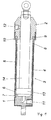
- the illustrated cylinder has a cylinder bottom 1, a cylinder head 2 and a cylinder shell extending between cylinder bottom 1 and cylinder head 2 3 on.
- the cylinder jacket 3 is formed by a composite body of a thin-walled, metallic inner tube 4 and an outer jacket 5 made of fiber-reinforced plastic that is connected to the inner tube 4 in a shear-resistant manner.
- fiber reinforcement preferably carbon fibers are used. The choice of plastic is naturally made depending on the particular load requirements.
- the inner tube 4 has on the side of the cylinder base 1 a thickened connection portion 6 with a thread 7, by means of which the inner tube 4 is connected in a tensile strength with the cylinder base 1.
- the inner tube 4 is also provided with a thickened end portion 8, which, however, forms an end-side annular flange 9.
- This annular flange 9 is overlapped by a screw-mounted on the cylinder head 2 screw nut 10, so that a tensile connection with the cylinder head 2 is made by the nut 10, which can be removed after loosening the nut 10 from the cylinder jacket 3.
- the outer sheath 5 made of fiber-reinforced plastic extends in the region of the end portion 8 of the inner tube 4 to the annular flange 9 and is therefore enclosed by the union nut 10.
- the outer shell 5 is extended beyond the thickened end portion 6 out and overlaps the cylinder base 1 frontally, whereby the axial connection of the cylinder jacket 3 is advantageously supported on the cylinder base 1, especially if the outer jacket 5 also with the Cylinder bottom 1 is shear-resistant connected by an adhesive layer.
- the connections 11 and 12 are guided for the hydraulic fluid through the cylinder base 1 and the cylinder head 2, the load capacity of the cylinder jacket 3 is not affected by these connections 11 and 12.
- the metallic inner tube 4 which preferably consists of a corrosion-resistant steel
- the outer jacket 5 made of plastic from an immediate load Protected by the hydraulic fluid, so that any existing microporosity of the fiber-reinforced plastic leads to no strength restriction due to an immediate pressure load by the hydraulic fluid.
- the inner tube 4 may also be made of plastic, namely of a polyetheretherketone. Also in this case, the inner tube 4 is screwed to the cylinder base to achieve a secure axial connection. In addition, the inner tube 4 can be glued to the cylinder bottom.
- the piston 13 with the piston rod 14 may also be made of fiber-reinforced plastic, but this is not mandatory.
- a metallic coating is recommended in order to improve the sealing conditions for a high-pressure hydraulics.
Landscapes
- Engineering & Computer Science (AREA)
- Physics & Mathematics (AREA)
- Fluid Mechanics (AREA)
- Mechanical Engineering (AREA)
- General Engineering & Computer Science (AREA)
- Actuator (AREA)
- Pistons, Piston Rings, And Cylinders (AREA)
- Types And Forms Of Lifts (AREA)
- Superconductors And Manufacturing Methods Therefor (AREA)
- Separation By Low-Temperature Treatments (AREA)
- Rigid Pipes And Flexible Pipes (AREA)
Description
- Die Erfindung bezieht sich auf einen Zylinder für Hochdruckhydraulik mit einem zwischen einem Zylinderboden und einem Zylinderkopf verlaufenden Zylindermantel aus einem Innenrohr und einem auf das Innenrohr aufgebrachten Außenmantel aus faserverstärkten Kunststoff.
- Aus dem Dokument
NL 1 017 640 C2 - Die
US 4,867,044 A zeigt einen Hydraulikzylinder mit einem Zylindermantel der aus einem mit einem napfförmigen Zylinderkopf und Zylinderboden zugfest verbundenen Mantelrohr. Auf das Mantelrohr und entgegen gesetzten Stirnflächen des Zylinderkopfes und Zylinderbodens bereichsweise umfassend ist eine Außenlage aus faserverstärktem Kunststoff aufgebracht. - Aus dem Dokument
US 5,415,079 A ist ein Hydraulikzylinder, insbesondere für die Verwendung in Flugzeugen, in Verbundbauweise bekannt. Dieser besteht aus einem im Wesentlichen dünnwandigen Innenrohr mit einem Innengewinde, für die Befestigung eines Zylinderbodens und eines Zylinderkopfes, in verdickten Endabschnitten. Das Zylinderrohr mit den verdickten Endabschnitten ist an der Außenoberfläche mit bevorzugt mehreren in Form von Spiralwickel aufgebrachter faserverstärkter Kunststofflagen versehen. - Aus dem Dokument
DE 196 49 133 C1 ist ein Zylindermantel für einen Hydraulikzylinder mit einem Innenrohr und mit einer auf das Innenrohr aufgebrachten Außenstruktur aus faserverstärktem Kunststoff bekannt. Das Innenrohr weist an beiden Zylinderenden Abschnitte mit mehreren zueinander beabstandeten, radial verlaufenden Verstärkungen auf. - Am Außenumfang des Innenrohres sind mit diesen formschlüssig verbunden, in axialer Faserausrichtung faserverstärkte Kunststofflagen aufgebracht, welche in den Endbereichen mit den radial umlaufenden Verstärkungen durch in radialer Faserausrichtung verlaufenden Faserlagen ummantelt sind.
- Aus dem Dokument
DE 36 17 957 A1 ist ein Gas/Öl- Druckakkumulator, insbesondere für hydraulische Steuerkreise bekannt, der durch einen zylindrischen Körper mit endseitig geschlossenen Böden gebildet ist. Im Inneren eines zylindrischen Mantelabschnittes ist ein verschiebbarer Kolben, welcher den Innenraum in zwei Kammern unterteilt, angeordnet, wovon eine ein Hydrauliköl und die weitere für ein Druckgas ausgelegt ist. Ein den zylindrischen Körper ausbildender Mantel wird aus einem Innenmantel aus Metall geringerer Dicke gebildet, auf dem eine Spiralwickellage aus faserverstärktem Kunststoff aufgebracht ist, die zumindest einen der Böden stirnseitig bereichsweise ummantelt. - Um die Korrosionsempfindlichkeit metallischer Druckzylinder zu vermeiden und Gewicht einzusparen, ist es bekannt, (
DE 69 16 307 U ), den Zylindermantel zwischen einem Zylinderboden und einem mit dem Zylinderboden über Zuganker verbundenen Zylinderkopf aus einem glasfaserverstärkten Kunststoffrohr auszubilden. Diese bekannten Druckzylinder sind jedoch für eine Hochdruckhydraulik mit hydrostatischen Drücken beispielsweise über 200 bar nicht geeignet. Es wurde daher vorgeschlagen (EP 0 701 065 B1 ), den Zylindermantel aus einem dünnwandigen, metallischen Innenrohr und einem faserverstärkten Außenmantel herzustellen, der über Zuganker unter einer geringen Vorspannung steht. Die radialen Druckkräfte werden über das dünnwandige Innenrohr auf den faserverstärkten Außenmantel übertragen, der diese Druckkräfte aufnimmt, ohne ein Undichtwerden des Zylinders befürchten zu müssen, weil der Außenmantel aus faserverstärktem Kunststoff von axialen Zugbelastungen frei bleibt. Die durch Hochdruckhydraulik bedingten axialen Kräfte werden ausschließlich durch die Zuganker aufgenommen. Nachteilig bei diesen bekannten Zylindern ist, daß die für Aufnahme der axialen Kräfte erforderlichen Zuganker nicht nur den Bauaufwand und die Zylinderabmessungen vergrößern, sondern auch eine Gewichtserhöhung mit sich bringen. - Der Erfindung liegt somit die Aufgabe zugrunde, einen Zylinder für Hochdruckhydraulik der eingangs geschilderten Art so auszugestalten, daß mit einfachen konstruktiven Mitteln auf den Einsatz von Zugankern zur Aufnahme der axialen Kräfte verzichtet werden kann.
- Die Erfindung löst die gestellte Aufgabe dadurch, daß das mit dem Zylinderboden verschraubte, mit dem Außenmantel schubfest verbundene Innenrohr des Zylindermantels zugfest am Zylinderkopf angreift.
- Durch das Verschrauben des Innenrohres mit dem Zylinderboden und die zugfeste Verbindung dieses Innenrohres mit dem Zylinderkopf können die auftretenden Axialkräfte in überraschender Weise auch bei einer Hochdruckhydraulik durch den Zylindermantel aufgenommen werden, wenn durch eine schubfeste Verbindung des Außenmantels aus faserverstärktem Kunststoff mit dem Innenrohr ein entsprechender, sowohl in Umfangsrichtung als auch in axialer Richtung wirksamer Verbundkörper geschaffen wird. Durch das Vorsehen mehrerer Lagen unterschiedlich ausgerichteter Verstärkungsfasern, vorzugsweise Kohlenstoffasern, kann der Außenmantel des Zylindermantels in einfacher Weise an die jeweiligen Belastungsanforderungen angepaßt werden. Mit dem Wegfall von Zugankern werden somit besonders leichte Druckzylinder möglich, die trotz der leichten Bauweise für eine Hochdruckhydraulik eingesetzt werden können.
- Das Innenrohr kann dabei in an sich bekannter Weise aus Metall, aber auch aus einem Polyetheretherketon (PEEK) bestehen, weil in beiden Fällen nicht nur die axialen Zugkräfte im Verbund mit dem Außenmantel aus faserverstärktem Kunststoff aufgenommen werden können, sondern auch der Außenmantel vor einer unmittelbaren Belastung durch das Hydraulikmittel geschützt wird, so daß die Festigkeitseigenschaften des faserverstärkten Kunststoffes nicht durch in Mikroporen eindringendes Hydraulikmittel beeinträchtigt werden können.
- Besonders günstige Anbindungsverhältnisse für den Zylindermantel an den Zylinderboden ergeben sich, wenn der Außenmantel aus Kunststoff mit dem Zylinderboden schubfest verbunden wird und den Zylinderboden stirnseitig übergreift, so daß die axiale Krafteinleitung in den Außenmantel nicht ausschließlich über die Schubkräfte zwischen dem Innenrohr und dem Außenmantel erfolgt. Die schubfeste Verbindung zwischen dem Außenmantel aus faserverstärktem Kunststoff mit dem Innenrohr bzw. dem Zylinderboden kann in einfacher Weise durch eine Klebeschicht erreicht werden.
- Die zugfeste Anbindung des Zylinderkopfes an den Zylindermantel kann in ähnlicher Weise wie die Anbindung des Zylinderbodens konstruktiv gelöst werden, was jedoch ein nachträgliches Abnehmen des Zylinderkopfes vom Zylindermantel und damit einen möglichen Kolbenausbau ausschließt. Aus diesem Grunde weist das Innenrohr des Zylindermantels auf der Zylinderkopfseite einen stirnseitigen Ringflansch auf, der durch eine am Zylinderkopf vorgesehene Überwurfmutter übergriffen wird, so daß mit Hilfe dieser Überwurfmutter die notwendige zugfeste Verbindung zwischen dem Innenrohr des Zylindermantels und dem Zylinderkopf sichergestellt werden kann. Der Außenmantel aus faserverstärktem Kunststoff erstreckt sich bis zum zylinderkopfseitigen Ringflansch des Innenrohres.
- In der Zeichnung ist der Erfindungsgegenstand beispielsweise dargestellt, und zwar wird ein erfindungsgemäßer Zylinder für Hochdruckhydraulik in einem vereinfachten Längsschnitt gezeigt.
- Der dargestellte Zylinder weist einen Zylinderboden 1, einen Zylinderkopf 2 sowie einen zwischen Zylinderboden 1 und Zylinderkopf 2 verlaufenden Zylindermantel 3 auf. Der Zylindermantel 3 wird durch einen Verbundkörper aus einem dünnwandigen, metallischen Innenrohr 4 und einem mit dem Innenrohr 4 schubfest verbundenen Außenmantel 5 aus faserverstärktem Kunststoff gebildet. Zur Faserverstärkung werden dabei vorzugsweise Kohlenstoffasern eingesetzt. Die Auswahl des Kunststoffes erfolgt naturgemäß in Abhängigkeit von den jeweiligen Belastungsanforderungen.
- Das Innenrohr 4 weist auf der Seite des Zylinderbodens 1 einen verdickten Anschlußabschnitt 6 mit einem Gewinde 7 auf, mit dessen Hilfe das Innenrohr 4 zugfest mit dem Zylinderboden 1 verbunden ist. Auf der Zylinderkopfseite ist das Innenrohr 4 ebenfalls mit einem verdickten Endabschnitt 8 versehen, der jedoch einen stirnseitigen Ringflansch 9 bildet. Dieser Ringflansch 9 wird von einer auf dem Zylinderkopf 2 schraubverstellbar gelagerten Überwurfmutter 10 übergriffen, so daß durch die Überwurfmutter 10 eine zugfeste Verbindung mit dem Zylinderkopf 2 hergestellt wird, der nach dem Lösen der Überwurfmutter 10 vom Zylindermantel 3 abgenommen werden kann.
- Der Außenmantel 5 aus faserverstärktem Kunststoff erstreckt sich im Bereich des Endabschnittes 8 des Innenrohres 4 bis zum Ringflansch 9 und wird daher von der Überwurfmutter 10 umschlossen. Auf der gegenüberliegenden Seite des Innenrohres 4 ist der Außenmantel 5 über den verdickten Endabschnitt 6 hinaus verlängert und übergreift den Zylinderboden 1 stirnseitig, wodurch die axiale Anbindung des Zylindermantels 3 an den Zylinderboden 1 vorteilhaft unterstützt wird, insbesondere dann, wenn der Außenmantel 5 auch mit dem Zylinderboden 1 durch eine Klebeschicht schubfest verbunden wird.
- Da die Anschlüsse 11 und 12 für das Hydraulikmittel durch den Zylinderboden 1 und den Zylinderkopf 2 geführt sind, wird die Belastbarkeit des Zylindermantels 3 durch diese Anschlüsse 11 und 12 nicht beeinträchtigt. Über den Zylindermantel 3 werden die radialen und axialen Druckkräfte aufgenommen, wobei das metallische Innenrohr 4, das vorzugsweise aus einem korrosionsfesten Stahl besteht, den Außenmantel 5 aus Kunststoff vor einer unmittelbaren Belastung durch das Hydraulikmittel schützt, so daß eine allenfalls vorhandene Mikroporosität des faserverstärkten Kunststoffes zu keiner Festigkeitseinschränkung aufgrund einer unmittelbaren Druckbelastung durch das Hydraulikmittel führt.
- Das Innenrohr 4 kann auch aus Kunststoff gefertigt sein, und zwar aus einem Polyetheretherketon. Auch in diesem Fall wird das Innenrohr 4 mit dem Zylinderboden verschraubt, um eine sichere axiale Anbindung zu erreichen. Zusätzlich kann das Innenrohr 4 mit dem Zylinderboden verklebt werden.
- Der Kolben 13 mit der Kolbenstange 14 können ebenfalls aus faserverstärktem Kunststoff hergestellt sein, was jedoch nicht zwingend ist. Bei der Ausformung der Kolbenstange 14 aus Kunststoff empfiehlt sich allerdings eine metallische Beschichtung, um die Dichtungsbedingungen für eine Hochdruckhydraulik zu verbessern.
Claims (6)
- Zylinder für Hochdruckhydraulik mit einem zwischen einem Zylinderboden (1) und einem Zylinderkopf (2) verlaufenden Zylindermantel (3) aus einem Innenrohr (4) und einem auf das Innenrohr (4) aufgebrachten Außenmantel (5) aus faserverstärktem Kunststoff, wobei das mit dem Zylinderboden (1) verschraubte, mit dem Außenmantel (5) schubfest verbundene Innenrohr (4) des Zylindermantels (3) zugfest am Zylinderkopf (2) angreift, dadurch gekennzeichnet, dass sich der Außenmantel (5) aus faserverstärkten Kunststoff zylinderkopfseitig bis zu einem stirnseitigen Ringflansch (9) des Innenrohres (4) erstreckt und dass der Zylinderkopf (2) eine den Ringflansch (9) übergreifende Überwurfmutter (10) trägt, durch die die zugfeste Verbindung zwischen dem Innenrohr (4) und dem Zylinderkopf (2) sichergestellt wird.
- Zylinder nach Anspruch 1, dadurch gekennzeichnet, dass das Innenrohr in an sich bekannter Weise aus Metall, vorzugsweise Stahl, besteht.
- Zylinder nach Anspruch 1, dadurch gekennzeichnet, dass das Innenrohr aus Polyetheretherketon besteht.
- Zylinder nach einem der Ansprüche 1 bis 3, dadurch gekennzeichnet, dass der schubfest mit dem Zylinderboden (1) verbundene Außenmantel (5) aus faserverstärktem Kunststoff den Zylinderboden (1) stirnseitig übergreift.
- Zylinder nach einem der Ansprüche 1 bis 4, dadurch gekennzeichnet, dass der Außenmantel (5) aus faserverstärkten Kunststoff mit dem Innenrohr (4) durch eine Klebeschicht schubfest verbunden ist.
- Zylinder nach einem der Ansprüche 1 bis 5, dadurch gekennzeichnet, dass das Innenrohr (4) auf der Seite des Zylinderbodens (1) mit einem verdickten Anschlussabschnitt (6) und auf der Zylinderkopfseite mit einem verdickten Endabschnitt (8) versehen ist.
Applications Claiming Priority (2)
| Application Number | Priority Date | Filing Date | Title |
|---|---|---|---|
| AT0198004A AT502447B1 (de) | 2004-11-25 | 2004-11-25 | Zylinder für hochdruckhydraulik |
| PCT/AT2005/000472 WO2006055997A1 (de) | 2004-11-25 | 2005-11-24 | Zylinder für hochdruckhydraulik |
Publications (2)
| Publication Number | Publication Date |
|---|---|
| EP1819928A1 EP1819928A1 (de) | 2007-08-22 |
| EP1819928B1 true EP1819928B1 (de) | 2010-08-25 |
Family
ID=35953816
Family Applications (1)
| Application Number | Title | Priority Date | Filing Date |
|---|---|---|---|
| EP05804672A Expired - Lifetime EP1819928B1 (de) | 2004-11-25 | 2005-11-24 | Zylinder für hochdruckhydraulik |
Country Status (5)
| Country | Link |
|---|---|
| US (1) | US20100077918A1 (de) |
| EP (1) | EP1819928B1 (de) |
| AT (2) | AT502447B1 (de) |
| DE (1) | DE502005010149D1 (de) |
| WO (1) | WO2006055997A1 (de) |
Cited By (1)
| Publication number | Priority date | Publication date | Assignee | Title |
|---|---|---|---|---|
| WO2014114498A1 (de) * | 2013-01-28 | 2014-07-31 | Zf Friedrichshafen Ag | Zylinderaggregat mit einer klebeverbindung |
Families Citing this family (14)
| Publication number | Priority date | Publication date | Assignee | Title |
|---|---|---|---|---|
| NZ561410A (en) | 2007-09-11 | 2010-04-30 | Parker Hannifin Gmbh | End-fittings for composite tubes, method for joining fittings to the ends of composite tubes and composite tubes incorporating end-fittings |
| DE102010024126A1 (de) * | 2010-06-17 | 2011-12-22 | Carl Freudenberg Kg | Kolbenspeicher |
| CN102705293B (zh) * | 2012-06-14 | 2014-04-09 | 中联重科股份有限公司 | 致动缸的缸体及其制造方法和混凝土泵送设备 |
| CN103075387B (zh) * | 2013-01-21 | 2015-08-05 | 四川重汽王牌兴城液压件有限公司 | 2tg-e110×90液压油缸进油机构及其生产方法 |
| FR3002187B1 (fr) * | 2013-02-20 | 2016-07-22 | Peugeot Citroen Automobiles Sa | Dispositif d'amortissement a jambe de force hybride, pour un train avant de vehicule |
| DE102015211545B3 (de) * | 2015-06-23 | 2016-11-10 | Innotec Lightweight Engineering & Polymer Technology Gmbh | Zylinderrohr für einen Hydraulik- oder Pneumatikzylinder |
| CN105673609B (zh) * | 2016-03-17 | 2018-11-16 | 中联重科股份有限公司 | 复合材料套筒和液压缸 |
| CN105587709B (zh) * | 2016-03-17 | 2018-03-06 | 中联重科股份有限公司 | 液压缸 |
| US10272991B2 (en) | 2016-06-23 | 2019-04-30 | Goodrich Corporation | Metallic composite joint |
| CN107693292A (zh) * | 2017-10-26 | 2018-02-16 | 广州艾捷斯医疗器械有限公司 | 一种靠背可伸缩的儿童牙科综合治疗机 |
| AU2018203763A1 (en) * | 2018-05-29 | 2019-12-19 | Turnbull, Sam Dominic Seaton MR | Intrascopic Cylinder |
| DE102021209068A1 (de) * | 2021-08-18 | 2023-02-23 | Festo Se & Co. Kg | Fluidbetätigter Arbeitszylinder und diesbezügliches Herstellungsverfahren |
| JP7431919B1 (ja) * | 2022-10-19 | 2024-02-15 | カヤバ株式会社 | 流体圧シリンダ |
| PL4261385T3 (pl) * | 2023-01-24 | 2025-03-24 | Dwl Baumaschinen Ag | Zespół przeciskający do urządzenia przeciskającego do przewodów bezwykopowych |
Family Cites Families (16)
| Publication number | Priority date | Publication date | Assignee | Title |
|---|---|---|---|---|
| US2865693A (en) * | 1954-05-18 | 1958-12-23 | George E Barnhart | Cylinder construction |
| US3334773A (en) * | 1965-04-12 | 1967-08-08 | Charles W Bimba | Fluid motor with removable-locking end closure unit |
| DE6916307U (de) | 1969-04-23 | 1969-09-04 | Kloeckner Werke Ag | Druckzylinder |
| JPS5864715A (ja) * | 1981-10-12 | 1983-04-18 | 三菱電機株式会社 | 炭化水素地下資源電気加熱用電極装置の電気絶縁被覆された導管の製造法 |
| JPS603388A (ja) * | 1983-06-17 | 1985-01-09 | 三菱電機株式会社 | 炭化水素地下資源電気加熱用電極支持導管およびその製法 |
| US4697499A (en) * | 1984-08-20 | 1987-10-06 | Pneumo Corporation | Dual tandem composite cylinder assembly |
| US4685384A (en) * | 1984-08-20 | 1987-08-11 | Pneumo Corporation | Fluid actuator including composite cylinder assembly |
| CA1251379A (en) * | 1984-08-20 | 1989-03-21 | William Dirkin | Fluid actuator including composite cylinder assembly |
| US4867044A (en) * | 1984-11-26 | 1989-09-19 | The United States Of America As Represented By The Secretary Of The Navy | Jam resistant fluid power actuator for ballistic-damage tolerant redundant cylinder assemblies |
| IT1185613B (it) * | 1985-05-30 | 1987-11-12 | Magnaghi Cleodinamica Spa | Accumulatore di pressione gas-olio con struttura in materiali compositi per circuiti idraulici di velivoli |
| US5415079A (en) * | 1992-05-13 | 1995-05-16 | Hr Textron, Inc. | Composite cylinder for use in aircraft hydraulic actuator |
| DE4430502C2 (de) | 1994-08-27 | 1999-08-19 | Lingk & Sturzebecher Gmbh | Verwendung eines Verbundaggregates aus einem Liner und einem faserverstärkten Kunststoffrohr als Druckzylinder eines Stelltriebes der Hochdruckhydraulik |
| US5651303A (en) * | 1994-11-14 | 1997-07-29 | Polygon Company | Fluid cylinder end cap assembly |
| DE19649133C1 (de) * | 1996-11-27 | 1998-03-05 | Dornier Gmbh | Hydraulik-Zylinder |
| NL1017640C2 (nl) * | 2001-03-19 | 2002-09-20 | Steon Holding B V | Cilinder en zuiger-cilindersamenstel. |
| WO2004070163A1 (en) * | 2003-02-03 | 2004-08-19 | Baker Hughes Incorporated | Composite inflatable downhole packer or bridge plug |
-
2004
- 2004-11-25 AT AT0198004A patent/AT502447B1/de not_active IP Right Cessation
-
2005
- 2005-11-24 DE DE502005010149T patent/DE502005010149D1/de not_active Expired - Lifetime
- 2005-11-24 US US11/720,305 patent/US20100077918A1/en not_active Abandoned
- 2005-11-24 EP EP05804672A patent/EP1819928B1/de not_active Expired - Lifetime
- 2005-11-24 WO PCT/AT2005/000472 patent/WO2006055997A1/de not_active Ceased
- 2005-11-24 AT AT05804672T patent/ATE479024T1/de active
Cited By (1)
| Publication number | Priority date | Publication date | Assignee | Title |
|---|---|---|---|---|
| WO2014114498A1 (de) * | 2013-01-28 | 2014-07-31 | Zf Friedrichshafen Ag | Zylinderaggregat mit einer klebeverbindung |
Also Published As
| Publication number | Publication date |
|---|---|
| US20100077918A1 (en) | 2010-04-01 |
| WO2006055997A1 (de) | 2006-06-01 |
| EP1819928A1 (de) | 2007-08-22 |
| DE502005010149D1 (de) | 2010-10-07 |
| AT502447B1 (de) | 2007-06-15 |
| ATE479024T1 (de) | 2010-09-15 |
| AT502447A1 (de) | 2007-03-15 |
Similar Documents
| Publication | Publication Date | Title |
|---|---|---|
| AT502447B1 (de) | Zylinder für hochdruckhydraulik | |
| EP0701065B1 (de) | Druckzylinder für Hochdruckhydraulik | |
| DE19508193C2 (de) | Rohrförmiges Bauteil oder Hohlprofil mit besonderen Festigkeitseigenschaften bei geringem Gewicht sowie Verfahren zu seiner Herstellung | |
| DE3617957A1 (de) | Druckakkumulator | |
| CH631533A5 (de) | Formschluessige rohrverbindung und verfahren zu ihrer herstellung. | |
| WO2017080723A1 (de) | Druckbehälter mit einem lastring, kraftfahrzeug und verfahren zur herstellung eines druckbehälters | |
| DE2926493C2 (de) | Strebe für Längszug und -druck | |
| DE102015204623A1 (de) | Kryogener Druckbehälter und Verfahren zum Montieren eines kryogenen Druckbehälters | |
| DE19647506C2 (de) | Kolbenstange für einen Stellkolben eines Stelltriebs | |
| DE102014226550A1 (de) | Aufhängung zur Anbringung eines Innenbehälters an einem Außenbehälter, kryogener Druckbehälter sowie Verfahren zur Herstellung einer Aufhängung | |
| EP1413744A1 (de) | Druckspeicher für ein Common Rail System | |
| DE19645467A1 (de) | Vorrichtung zur Krafteinleitung | |
| DE102014000617B4 (de) | Druckgasbehälter | |
| DE2248589A1 (de) | Elektrisch isolierende rohrkupplung | |
| DE102013018970B3 (de) | Faserverbundrohr | |
| DE3516814A1 (de) | Kupplungsmuffe aus kunststoff fuer rohre | |
| EP2527589A2 (de) | Gesteinsanker | |
| EP1653138A1 (de) | Förderrohr für den Feststofftransport | |
| DE19649133C1 (de) | Hydraulik-Zylinder | |
| WO2010124815A1 (de) | Aus einem faserverstärkten kunststoff bestehende zylindrische körper | |
| DE102014226557A1 (de) | Aufhängung zur Anbringung eines Innenbehälters an einem Außenbehälter eines kryogenen Druckbehälters sowie kryogener Druckbehälter | |
| DE102017003024A1 (de) | Abschlusselement zur Krafteinleitung in ein vorgefertigtes Faserkunststoffverbundrohr | |
| DE102004021144B4 (de) | Anschluss zur Übertragung von Zugkräften in Stäben oder innerdruckbelasteten Röhren | |
| DE202006016041U1 (de) | Krafteinleitungselement für Faserverbundstreben in Flugzeugen | |
| DE19649378A1 (de) | Dichtung eines druckbeaufschlagten Zylinders |
Legal Events
| Date | Code | Title | Description |
|---|---|---|---|
| PUAI | Public reference made under article 153(3) epc to a published international application that has entered the european phase |
Free format text: ORIGINAL CODE: 0009012 |
|
| 17P | Request for examination filed |
Effective date: 20070622 |
|
| AK | Designated contracting states |
Kind code of ref document: A1 Designated state(s): AT BE BG CH CY CZ DE DK EE ES FI FR GB GR HU IE IS IT LI LT LU LV MC NL PL PT RO SE SI SK TR |
|
| AX | Request for extension of the european patent |
Extension state: AL BA HR MK YU |
|
| 17Q | First examination report despatched |
Effective date: 20080616 |
|
| RIN1 | Information on inventor provided before grant (corrected) |
Inventor name: MARK, RUDOLF Inventor name: HOELZL, OTHMAR Inventor name: FIEDLER, MARTIN |
|
| GRAP | Despatch of communication of intention to grant a patent |
Free format text: ORIGINAL CODE: EPIDOSNIGR1 |
|
| GRAS | Grant fee paid |
Free format text: ORIGINAL CODE: EPIDOSNIGR3 |
|
| GRAA | (expected) grant |
Free format text: ORIGINAL CODE: 0009210 |
|
| AK | Designated contracting states |
Kind code of ref document: B1 Designated state(s): AT BE BG CH CY CZ DE DK EE ES FI FR GB GR HU IE IS IT LI LT LU LV MC NL PL PT RO SE SI SK TR |
|
| AX | Request for extension of the european patent |
Extension state: AL BA HR MK YU |
|
| REG | Reference to a national code |
Ref country code: GB Ref legal event code: FG4D Free format text: NOT ENGLISH |
|
| REG | Reference to a national code |
Ref country code: CH Ref legal event code: EP |
|
| REG | Reference to a national code |
Ref country code: IE Ref legal event code: FG4D Free format text: LANGUAGE OF EP DOCUMENT: GERMAN |
|
| REF | Corresponds to: |
Ref document number: 502005010149 Country of ref document: DE Date of ref document: 20101007 Kind code of ref document: P |
|
| REG | Reference to a national code |
Ref country code: NL Ref legal event code: VDEP Effective date: 20100825 |
|
| LTIE | Lt: invalidation of european patent or patent extension |
Effective date: 20100825 |
|
| PG25 | Lapsed in a contracting state [announced via postgrant information from national office to epo] |
Ref country code: LT Free format text: LAPSE BECAUSE OF FAILURE TO SUBMIT A TRANSLATION OF THE DESCRIPTION OR TO PAY THE FEE WITHIN THE PRESCRIBED TIME-LIMIT Effective date: 20100825 Ref country code: FI Free format text: LAPSE BECAUSE OF FAILURE TO SUBMIT A TRANSLATION OF THE DESCRIPTION OR TO PAY THE FEE WITHIN THE PRESCRIBED TIME-LIMIT Effective date: 20100825 |
|
| PG25 | Lapsed in a contracting state [announced via postgrant information from national office to epo] |
Ref country code: SI Free format text: LAPSE BECAUSE OF FAILURE TO SUBMIT A TRANSLATION OF THE DESCRIPTION OR TO PAY THE FEE WITHIN THE PRESCRIBED TIME-LIMIT Effective date: 20100825 Ref country code: BG Free format text: LAPSE BECAUSE OF FAILURE TO SUBMIT A TRANSLATION OF THE DESCRIPTION OR TO PAY THE FEE WITHIN THE PRESCRIBED TIME-LIMIT Effective date: 20101125 Ref country code: CY Free format text: LAPSE BECAUSE OF FAILURE TO SUBMIT A TRANSLATION OF THE DESCRIPTION OR TO PAY THE FEE WITHIN THE PRESCRIBED TIME-LIMIT Effective date: 20100825 Ref country code: IS Free format text: LAPSE BECAUSE OF FAILURE TO SUBMIT A TRANSLATION OF THE DESCRIPTION OR TO PAY THE FEE WITHIN THE PRESCRIBED TIME-LIMIT Effective date: 20101225 Ref country code: PL Free format text: LAPSE BECAUSE OF FAILURE TO SUBMIT A TRANSLATION OF THE DESCRIPTION OR TO PAY THE FEE WITHIN THE PRESCRIBED TIME-LIMIT Effective date: 20100825 Ref country code: PT Free format text: LAPSE BECAUSE OF FAILURE TO SUBMIT A TRANSLATION OF THE DESCRIPTION OR TO PAY THE FEE WITHIN THE PRESCRIBED TIME-LIMIT Effective date: 20101227 |
|
| REG | Reference to a national code |
Ref country code: IE Ref legal event code: FD4D |
|
| PG25 | Lapsed in a contracting state [announced via postgrant information from national office to epo] |
Ref country code: SE Free format text: LAPSE BECAUSE OF FAILURE TO SUBMIT A TRANSLATION OF THE DESCRIPTION OR TO PAY THE FEE WITHIN THE PRESCRIBED TIME-LIMIT Effective date: 20100825 Ref country code: NL Free format text: LAPSE BECAUSE OF FAILURE TO SUBMIT A TRANSLATION OF THE DESCRIPTION OR TO PAY THE FEE WITHIN THE PRESCRIBED TIME-LIMIT Effective date: 20100825 Ref country code: LV Free format text: LAPSE BECAUSE OF FAILURE TO SUBMIT A TRANSLATION OF THE DESCRIPTION OR TO PAY THE FEE WITHIN THE PRESCRIBED TIME-LIMIT Effective date: 20100825 Ref country code: GR Free format text: LAPSE BECAUSE OF FAILURE TO SUBMIT A TRANSLATION OF THE DESCRIPTION OR TO PAY THE FEE WITHIN THE PRESCRIBED TIME-LIMIT Effective date: 20101126 |
|
| PG25 | Lapsed in a contracting state [announced via postgrant information from national office to epo] |
Ref country code: DK Free format text: LAPSE BECAUSE OF FAILURE TO SUBMIT A TRANSLATION OF THE DESCRIPTION OR TO PAY THE FEE WITHIN THE PRESCRIBED TIME-LIMIT Effective date: 20100825 Ref country code: IE Free format text: LAPSE BECAUSE OF FAILURE TO SUBMIT A TRANSLATION OF THE DESCRIPTION OR TO PAY THE FEE WITHIN THE PRESCRIBED TIME-LIMIT Effective date: 20100825 |
|
| BERE | Be: lapsed |
Owner name: HOLZL, MARGIT Effective date: 20101130 |
|
| PG25 | Lapsed in a contracting state [announced via postgrant information from national office to epo] |
Ref country code: CZ Free format text: LAPSE BECAUSE OF FAILURE TO SUBMIT A TRANSLATION OF THE DESCRIPTION OR TO PAY THE FEE WITHIN THE PRESCRIBED TIME-LIMIT Effective date: 20100825 Ref country code: EE Free format text: LAPSE BECAUSE OF FAILURE TO SUBMIT A TRANSLATION OF THE DESCRIPTION OR TO PAY THE FEE WITHIN THE PRESCRIBED TIME-LIMIT Effective date: 20100825 Ref country code: IT Free format text: LAPSE BECAUSE OF FAILURE TO SUBMIT A TRANSLATION OF THE DESCRIPTION OR TO PAY THE FEE WITHIN THE PRESCRIBED TIME-LIMIT Effective date: 20100825 Ref country code: SK Free format text: LAPSE BECAUSE OF FAILURE TO SUBMIT A TRANSLATION OF THE DESCRIPTION OR TO PAY THE FEE WITHIN THE PRESCRIBED TIME-LIMIT Effective date: 20100825 Ref country code: RO Free format text: LAPSE BECAUSE OF FAILURE TO SUBMIT A TRANSLATION OF THE DESCRIPTION OR TO PAY THE FEE WITHIN THE PRESCRIBED TIME-LIMIT Effective date: 20100825 |
|
| PGFP | Annual fee paid to national office [announced via postgrant information from national office to epo] |
Ref country code: AT Payment date: 20110325 Year of fee payment: 6 |
|
| PG25 | Lapsed in a contracting state [announced via postgrant information from national office to epo] |
Ref country code: MC Free format text: LAPSE BECAUSE OF NON-PAYMENT OF DUE FEES Effective date: 20101130 Ref country code: ES Free format text: LAPSE BECAUSE OF FAILURE TO SUBMIT A TRANSLATION OF THE DESCRIPTION OR TO PAY THE FEE WITHIN THE PRESCRIBED TIME-LIMIT Effective date: 20101206 |
|
| REG | Reference to a national code |
Ref country code: CH Ref legal event code: PL |
|
| PLBE | No opposition filed within time limit |
Free format text: ORIGINAL CODE: 0009261 |
|
| STAA | Information on the status of an ep patent application or granted ep patent |
Free format text: STATUS: NO OPPOSITION FILED WITHIN TIME LIMIT |
|
| GBPC | Gb: european patent ceased through non-payment of renewal fee |
Effective date: 20101125 |
|
| PG25 | Lapsed in a contracting state [announced via postgrant information from national office to epo] |
Ref country code: CH Free format text: LAPSE BECAUSE OF NON-PAYMENT OF DUE FEES Effective date: 20101130 Ref country code: LI Free format text: LAPSE BECAUSE OF NON-PAYMENT OF DUE FEES Effective date: 20101130 |
|
| 26N | No opposition filed |
Effective date: 20110526 |
|
| PG25 | Lapsed in a contracting state [announced via postgrant information from national office to epo] |
Ref country code: BE Free format text: LAPSE BECAUSE OF NON-PAYMENT OF DUE FEES Effective date: 20101130 |
|
| REG | Reference to a national code |
Ref country code: DE Ref legal event code: R097 Ref document number: 502005010149 Country of ref document: DE Effective date: 20110526 |
|
| PG25 | Lapsed in a contracting state [announced via postgrant information from national office to epo] |
Ref country code: GB Free format text: LAPSE BECAUSE OF NON-PAYMENT OF DUE FEES Effective date: 20101125 |
|
| PG25 | Lapsed in a contracting state [announced via postgrant information from national office to epo] |
Ref country code: HU Free format text: LAPSE BECAUSE OF FAILURE TO SUBMIT A TRANSLATION OF THE DESCRIPTION OR TO PAY THE FEE WITHIN THE PRESCRIBED TIME-LIMIT Effective date: 20110226 Ref country code: LU Free format text: LAPSE BECAUSE OF NON-PAYMENT OF DUE FEES Effective date: 20101124 |
|
| PG25 | Lapsed in a contracting state [announced via postgrant information from national office to epo] |
Ref country code: TR Free format text: LAPSE BECAUSE OF FAILURE TO SUBMIT A TRANSLATION OF THE DESCRIPTION OR TO PAY THE FEE WITHIN THE PRESCRIBED TIME-LIMIT Effective date: 20100825 |
|
| REG | Reference to a national code |
Ref country code: AT Ref legal event code: MM01 Ref document number: 479024 Country of ref document: AT Kind code of ref document: T Effective date: 20111124 |
|
| PG25 | Lapsed in a contracting state [announced via postgrant information from national office to epo] |
Ref country code: AT Free format text: LAPSE BECAUSE OF NON-PAYMENT OF DUE FEES Effective date: 20111124 |
|
| REG | Reference to a national code |
Ref country code: FR Ref legal event code: PLFP Year of fee payment: 11 |
|
| REG | Reference to a national code |
Ref country code: FR Ref legal event code: PLFP Year of fee payment: 12 |
|
| PGFP | Annual fee paid to national office [announced via postgrant information from national office to epo] |
Ref country code: FR Payment date: 20161128 Year of fee payment: 12 |
|
| PGFP | Annual fee paid to national office [announced via postgrant information from national office to epo] |
Ref country code: DE Payment date: 20170131 Year of fee payment: 12 |
|
| REG | Reference to a national code |
Ref country code: DE Ref legal event code: R119 Ref document number: 502005010149 Country of ref document: DE |
|
| REG | Reference to a national code |
Ref country code: FR Ref legal event code: ST Effective date: 20180731 |
|
| PG25 | Lapsed in a contracting state [announced via postgrant information from national office to epo] |
Ref country code: DE Free format text: LAPSE BECAUSE OF NON-PAYMENT OF DUE FEES Effective date: 20180602 Ref country code: FR Free format text: LAPSE BECAUSE OF NON-PAYMENT OF DUE FEES Effective date: 20171130 |