EP1819948B1 - Riemenantrieb mit einem reibrad - Google Patents
Riemenantrieb mit einem reibrad Download PDFInfo
- Publication number
- EP1819948B1 EP1819948B1 EP05815753A EP05815753A EP1819948B1 EP 1819948 B1 EP1819948 B1 EP 1819948B1 EP 05815753 A EP05815753 A EP 05815753A EP 05815753 A EP05815753 A EP 05815753A EP 1819948 B1 EP1819948 B1 EP 1819948B1
- Authority
- EP
- European Patent Office
- Prior art keywords
- belt drive
- friction
- belt
- pulley
- impressions
- Prior art date
- Legal status (The legal status is an assumption and is not a legal conclusion. Google has not performed a legal analysis and makes no representation as to the accuracy of the status listed.)
- Expired - Lifetime
Links
Images



Classifications
-
- F—MECHANICAL ENGINEERING; LIGHTING; HEATING; WEAPONS; BLASTING
- F16—ENGINEERING ELEMENTS AND UNITS; GENERAL MEASURES FOR PRODUCING AND MAINTAINING EFFECTIVE FUNCTIONING OF MACHINES OR INSTALLATIONS; THERMAL INSULATION IN GENERAL
- F16H—GEARING
- F16H7/00—Gearings for conveying rotary motion by endless flexible members
- F16H7/02—Gearings for conveying rotary motion by endless flexible members with belts; with V-belts
-
- F—MECHANICAL ENGINEERING; LIGHTING; HEATING; WEAPONS; BLASTING
- F02—COMBUSTION ENGINES; HOT-GAS OR COMBUSTION-PRODUCT ENGINE PLANTS
- F02B—INTERNAL-COMBUSTION PISTON ENGINES; COMBUSTION ENGINES IN GENERAL
- F02B67/00—Engines characterised by the arrangement of auxiliary apparatus not being otherwise provided for, e.g. the apparatus having different functions; Driving auxiliary apparatus from engines, not otherwise provided for
- F02B67/04—Engines characterised by the arrangement of auxiliary apparatus not being otherwise provided for, e.g. the apparatus having different functions; Driving auxiliary apparatus from engines, not otherwise provided for of mechanically-driven auxiliary apparatus
- F02B67/06—Engines characterised by the arrangement of auxiliary apparatus not being otherwise provided for, e.g. the apparatus having different functions; Driving auxiliary apparatus from engines, not otherwise provided for of mechanically-driven auxiliary apparatus driven by means of chains, belts, or like endless members
-
- F—MECHANICAL ENGINEERING; LIGHTING; HEATING; WEAPONS; BLASTING
- F16—ENGINEERING ELEMENTS AND UNITS; GENERAL MEASURES FOR PRODUCING AND MAINTAINING EFFECTIVE FUNCTIONING OF MACHINES OR INSTALLATIONS; THERMAL INSULATION IN GENERAL
- F16H—GEARING
- F16H55/00—Elements with teeth or friction surfaces for conveying motion; Worms, pulleys or sheaves for gearing mechanisms
- F16H55/32—Friction members
- F16H55/34—Non-adjustable friction discs
-
- F—MECHANICAL ENGINEERING; LIGHTING; HEATING; WEAPONS; BLASTING
- F02—COMBUSTION ENGINES; HOT-GAS OR COMBUSTION-PRODUCT ENGINE PLANTS
- F02B—INTERNAL-COMBUSTION PISTON ENGINES; COMBUSTION ENGINES IN GENERAL
- F02B2275/00—Other engines, components or details, not provided for in other groups of this subclass
- F02B2275/06—Endless member is a belt
-
- F—MECHANICAL ENGINEERING; LIGHTING; HEATING; WEAPONS; BLASTING
- F16—ENGINEERING ELEMENTS AND UNITS; GENERAL MEASURES FOR PRODUCING AND MAINTAINING EFFECTIVE FUNCTIONING OF MACHINES OR INSTALLATIONS; THERMAL INSULATION IN GENERAL
- F16H—GEARING
- F16H13/00—Gearing for conveying rotary motion with constant gear ratio by friction between rotary members
- F16H13/10—Means for influencing the pressure between the members
- F16H13/14—Means for influencing the pressure between the members for automatically varying the pressure mechanically
Definitions
- the present invention relates to a belt drive with a friction wheel for an internal-combustion (IC) engine of a vehicle, according to the preamble of claim 1.
- IC internal-combustion
- the IC engine of a vehicle is generally connected to an electrical machine for the generation of electrical energy by means of a belt accessory drive.
- Accessory drives are known that comprise a pulley connected to a crankshaft of the IC engine, a pulley connected to the electrical machine, and a belt drive of the poly-V type wound around the aforesaid pulleys and possibly driving other engine accessories, such as a compressor of the air conditioning system.
- the water pump is permanently driven by the crankshaft via a belt or gear transmission.
- a known, alternative solution consists in driving the pump by a friction wheel that takes motion from the crankshaft and a pulley fitted on the water pump shaft and adapted to cooperate with one another by rolling friction.
- This arrangement can be used either as a permanent drive, i.e. allowing the water pump to be permanently driven by the crankshaft, or as a selectively activatable drive.
- DE-A-103 09 062 discloses a drive of the aforementioned type, in which the friction wheel has a peripheral elastomeric or plastics friction annulus having a sculpted profile for water drainage, in order to improve torque transmission to the water pump without any substantial slippage of the friction wheel in bad weather conditions.
- EP-A-1 464 870 discloses another belt and friction wheel drive of the type briefly discussed above, in which the friction wheel is made of plastics material and the water pump pulley is lined by a layer of soft material. Although the friction wheel is said to have a sculpted profile to assist drainage, no detail of such profile is disclosed.
- sculpted profiles e.g. grooved profiles or tyre-type profile
- a comparatively "hard” material of the friction wheel with respect to the belt back and water pump pulley has proven to bring about additional problems concerning both excessive wear of the belt, particularly where continuous circumferential grooves are used, and noise generation in use, particularly when circumferentially discontinuous, periodic patterns are used.
- torque transmission in wet condition, belt wear and noise are parameters that are difficult to be optimized all together because they call for contradictory measures.
- the purpose of the present invention is to provide a belt and friction wheel drive with high performance in wet conditions, which is free from the additional drawbacks, such as quick belt wear and noise, described above.
- a belt drive with a friction wheel as defined in Claim 1.
- FIG. 1 Designated as a whole by the reference number 1 in Figure 1 is a belt drive set in the vicinity of a vertical wall 2 of an IC engine 3 of a motor vehicle.
- the drive 1 comprises: a crankshaft pulley 4, which is rigidly connected to a crankshaft 5 of the engine 3 and is rotatable about an axis A of the crankshaft 5; a pulley 6 connected to a reversible electrical machine 7; a pulley 8 connected to a compressor of an air conditioning system, not shown; and a poly-V belt 9 wound around the pulleys 4, 6 and 8 for rotational connection of the crankshaft 5 to the reversible electrical machine 7.
- the drive 1 further comprises a two-armed belt tensioner 12, set in the proximity of the reversible electrical machine 7 and acting on respective branches 13 of the belt 9, comprised between the crankshaft pulley 4 and the pulley 6, and between the pulley 8 and the pulley 6, respectively.
- the drive 1 further includes a friction-wheel assembly 10 for selectively driving a water pump 11.
- the friction-wheel assembly 10 comprises a friction wheel 17 which is adapted to cooperate by rolling friction with a back 20 of the belt 9 at a section thereof that is wound around the crankshaft pulley 4, as well as with a friction pulley 14 connected to a drive shaft 15 of the water pump 11 and having an axis D.
- the friction wheel assembly 10 includes an arm 16 hinged at one end about an axis B parallel to the axis A and supporting at its opposite end the friction wheel 17, which is freely rotatable about an axis C carried by arm 16 and parallel to the axis B.
- the arm 16 is set between the pulley 4 and the friction pulley 14, whilst the axis B and the axis C are set on opposite sides with respect to the straight line joining the centres of the pulley 4 and of the friction pulley 14, respectively.
- the friction-wheel assembly 10 further comprises an actuating unit 18 for moving the arm 16 radially with respect to the axis A between an engagement position in which the friction wheel 17 co-operates both with the back 20 of the belt 9 and with the friction pulley 14 and thus the water pump 11 is driven, and a disengagement position, in which the friction wheel 17 is separated from the friction pulley 14 but remains in contact with the back 20 of the belt 9, the water pump 11 being thus uncoupled from the crankshaft 5.
- the friction wheel 17 is made of pressed steel and has a substantially cylindrical lateral wall defining a friction surface 19 ( Figure 3 ) obtained by knurling, i.e., provided with a plurality of impressions obtained via roll-forming.
- the knurling pattern 27 of the friction surface 19 is formed by two mutually inclined sheaves 28, 29 of rectilinear impressions 30 intersecting each other to form adjacent rhombuses ( Figure 3 and 4 ).
- Each sheave is formed by parallel, rectilinear impressions 30 spaced by a distance or pitch P, and the two 28, 29 sheaves are inclined in opposite directions with respect to the generatrices g ( Figure 4 ) of the friction surface 19.
- the angle ⁇ formed between each impression 30 and generatrices g ranges from 15° to 75°, and preferably between 15° and 45°. Most preferably, the angle is 30°. In the most preferred embodiment, the impressions 30 of the two sheaves mutually intersect forming angles ⁇ of 60°.
- the impressions 30 have a rounded bottom line 31 and flex-shaped flanks 32 which are smoothly connected both to the bottom line 31 and to the top line 33 of the profile defined by the cylindrical outer profile of friction surface 19.
- the flanks 32 form with the top line 33 transition areas 34 having a curvature radius greater than 0.05 mm and preferably of about 0.1 mm.
- a and D designate the width and depth of the impressions 30, respectively.
- the back 20 of the belt 9 comprises an embossed antiwear surface layer 21.
- the antiwear surface layer 21 comprises a fabric 22 that is so textured that warp and weft form a succession of relieves and recesses which define an embossed surface that moreover improves mechanical adhesion.
- the dimensions of relieves and recesses are preferably smaller that one millimeter.
- the fabric 22 is preferably constituted by a knitted cotton/polyester fabric or a polymeric material, preferably an aliphatic or aromatic polyamide, even more preferably a 6/6 polyamide with high thermal resistance and high toughness.
- the fabric 22 can also be of the type in which each thread of weft is constituted by an elastic thread as a core and by at least one composite thread wound on the elastic thread, where the composite thread comprises a thread with high thermal and mechanical resistance and at least one coating thread wound on the thread with high thermal and mechanical resistance.
- the friction pulley 14 comprises a supporting disc 24 and a friction annulus 25 made of elastomeric material, which is set peripherally on the supporting disc 24 and has a friction surface 26 co-operating by friction with the friction wheel 17.
- the friction annulus 25 can be overmoulded around the supporting disc 24 or be constituted by a pre-fabricated endless belt that is interference-fitted around the supporting disc 24.
- the friction annulus 25 is made of an EPDM-based rubber.
- the friction annulus 25 has a hardness, measured on the friction surface 26, of 85 to 99 Shore A and preferably of about 94 Shore A.
- friction surface 26 of the friction annulus 25 can be defined by an antiwear surface layer 21 ( Figure 2 ) including a fabric 22 as described above.
- the actuating unit 18 moves the friction wheel 17 away from the friction pulley 14, while keeping it in contact with the back 20 of the belt 9 (disengagement position).
- the water pump 11 is thus uncoupled from the crankshaft 5.
- the IC engine 4 is initially driven by reversible electrical machine 7 which operates as starter motor, and is ignited when a given speed threshold is reached.
- the actuating unit 18 maintains the friction wheel 17 in the disengaged potion until a warmed-up condition of the IC engine is reached.
- the actuating unit 18 is then switched and the friction wheel 17 is set in the engagement position and contacts both the back 20 of the belt 9 and the friction annulus 25.
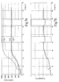
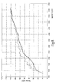
- FIGS 6a to 9 show the behaviour of the friction wheel according to the present invention, as of various operation features, in comparison with prior art friction wheels.
- Figures 6a , 7a are diagrams showing the speed of the water pump pulley 14 (curve W/P), of the crankshaft pulley 4 (curve C/S) and of the friction wheel 17 (curve FW) as a function of time, in an acceleration test in alternated wet and dry conditions.
- the friction wheel 17 was always maintained in the engaged position. Water was sprayed on friction surfaces to maintain them wet except for short time intervals (highlighted in the diagram) spaced in time after engine acceleration.
- Figures 6b , 7b shows the speed difference or slippage between the crankshaft pulley 4 and the water pump pulley 14, expressed as a percentage of the crankshaft speed.
- test of figures 6a, 6b was carried out using a "flat" friction wheel, i.e. a friction wheel having a cylindrical friction surface 19 with no knurling; the test of figures 7a, 7b was carried out using a friction wheel 17 having a knurled friction surface according to the pattern of figures 3 to 5 .
- the test with the flat friction wheel resulted in a slippage of about 25% in wet condition, which slippage rapidly reduced to about 3% in the dry condition intervals.
- the test with the knurled friction wheel in accordance with the present invention resulted in a slippage of less than 2% in wet conditions, which is only slightly more than that the slippage value in dry conditions.
- the knurled friction wheel 17 according to the present invention is therefore substantially insensitive to water and reveals a substantially steady behaviour both in dry and wet conditions.
- Figure 8 concerns a noise measurement test as a function of engine speed.
- Full-line, broken-line and dotted-line curves represent the results obtained by using the knurled friction wheel of the invention, a "flat" friction wheel and a tyre-like friction wheel.
- the knurled friction wheel noise curve is substantially identical to the flat friction wheel noise curve, and considerably better that the one obtained by using a tyre-like friction wheel.
- Figure 9 shows the belt wear produced by friction wheels of different types: "flat” (round markers), knurled (diamond markers), tyre-like (square markers).
- the test was carried out on a test bench by driving the crankshaft pulley at 6000 rpm, with a brake torque of 1.8 Nm on the water pump pulley 14, at a temperature of 100°C.
- the belt wear has been measured in terms of weight loss (g) of the belt as a function of time (h).
- the knurled friction wheel 17 of the present invention entails a slightly grater belt wear (about 1 g more after 300h of operation) with respect to a flat type friction wheel, but far less wear than a sculpted, tyre-type friction wheel which proved to lead to unacceptable wear (already 5 g after less than 70 hours of test).
- the friction wheel 17 is made entirely of metal, it offers guarantees of duration and reliability, and prevents the wedging effect.
- a friction annulus 25 is applied to the water pump pulley 14 instead of the friction wheel 17, the annulus undergoes the shearing stresses exerted by the friction wheel 17, only, which limits the harmful stresses to a minimum.
- the use of a friction annulus 25 having a hardness in the disclosed range allows wear of the annulus to be acceptable, without compromising torque transmission.
- the interaction between the metal friction wheel 17 and both the belt back 20 and the friction annulus 25 made of elastomeric material can be improved for the purposes of duration, by using the antiwear fabric 21, which increases the reliability of the drive.
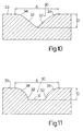
- Figures 10 and 11 show alternative cross-section profiles of impressions 30.
- the impression 30 of fig. 10 has a substantially V-shaped profile, with flat flanks 32 converging towards a substantially sharp bottom corner.
- Flanks 32 are smoothly connected to the top line 33 by rounded transition areas 34 having a curvature radius of 0.05 to 0.1 mm.
- A/D ratio may range between 0.5 and 10: a smaller width of the impression can be compensated by a greater depth for the purpose of the volume of water that can be drained off.
- figure 11 has a substantially rectangular profile in cross-section, with a flat bottom lime 31 and curved flanks 32 forming corners therewith. A/D rations between 1 and 10 can be suitable in this case.
- the friction annulus 25 can be filled with friction materials and consequently be less soft than the belt 9 that must ensure flexibility to enable winding around the pulleys 4, 6 and 8.
- the drive 1 can actuate an electrical machine of a traditional type, or alternator.
- the friction wheel assembly 10 can be designed for permanently driving the water pump 11; in this case, the actuating unit 18 can be dispensed with.
- the antiwear surface layer 21 may comprise an anti-abrasive layer 23, set on the outside of the fabric 22.
- the anti-abrasive layer 23 is constituted by a fluorinated plastomer with the addition of an elastomeric material, and the fluorinated plastomer is present in a greater weight percentage than the elastomeric material.
- the fluorinated plastomer is a polytetrafluoroethylene-based compound; for example, ZONYL MT 1500 can be used.
- the elastomeric material with which the fluorinated plastomer is mixed to form the anti-abrasive layer 23 is HNBR; even more preferably, it is an HNBR modified with a zinc salt of polymethacrylic acid; for example, ZEOFORTE ZSC (registered trademark of Nippon Zeon) can be used.
Landscapes
- Engineering & Computer Science (AREA)
- General Engineering & Computer Science (AREA)
- Mechanical Engineering (AREA)
- Chemical & Material Sciences (AREA)
- Combustion & Propulsion (AREA)
- Devices For Conveying Motion By Means Of Endless Flexible Members (AREA)
- Pulleys (AREA)
- Friction Gearing (AREA)
- Transmission Devices (AREA)
Claims (28)
- Riemenantrieb (1), der umfasst:eine erste Riemenscheibe (4), die um eine erste feststehende Achse (8) herum gedreht werden kann und mit einer Kurbelwelle eines Verbrennungsmotors verbunden ist;wenigstens eine zweite drehbare Riemenscheibe (6);einen Übertragungsriemen (9), der auf die erste und die zweite Riemenscheibe (4, 6) gewickelt ist und eine Riemenrückseite (20) hat;eine Reibscheibe (14), die mit einem Motorzubehörteil (11) verbunden ist und um eine zweite feststehende Achse (D) parallel zu der ersten Achse (A) gedreht werden kann; undein Reibrad (17), das um eine dritte Achse (C) parallel zu der ersten und der zweiten Achse (A, D) gedreht werden kann und eine Reibfläche (19) aufweist, die mit der Reibscheibe (14) und einer Rückseite (20) des Riemens (9) an einem Abschnitt desselben zusammenwirkt, der um die erste Riemenscheibe (4) herumgewickelt ist, wobei die Reibscheibe (14) einen Reibring (25) umfasst, der weicher ist als die Reibfläche (19) des Reibrads (17) und mit ihr zusammenwirkt, dadurch gekennzeichnet, dass das Reibrad (17) aus Metall besteht und die Reibfläche (19) gerändelt ist, wobei die Reibfläche (19) des Reibrades (17) ein Rändelmuster (27) aufweist, das durch wenigstens eine Rille (28, 29) aus rechteckigen Vertiefungen (30) gebildet wird, die in Bezug auf die Erzeugenden (g) der Reibfläche schräg verlaufen, und wobei die Vertiefungen (30) im Querschnitt ein Profil haben, das zwei Flanken (32) enthält, die stufenlos mit einer oberen Linie (33) verbunden sind und mit der oberen Linie (33) abgerundete Übergangsbereiche (34) bilden, die einen Krümmungsradius von mehr als 0,05 mm haben.
- Riemenantrieb nach Anspruch 1, dadurch gekennzeichnet, dass das Reibrad (17) aus gepresstem Stahl besteht.
- Riemenantrieb nach Anspruch 1 und 2, dadurch gekennzeichnet, dass das Rändelmuster (27) zwei schräg zueinander verlaufende Rillen (28, 29) aus rechteckigen Vertiefungen (30) enthält, die einander schneiden und aneinandergrenzende Rhomben bilden.
- Riemenantrieb nach Anspruch 3, dadurch gekennzeichnet, dass die zwei Rillen (28, 29) in Bezug auf die Erzeugenden (g) der Reibfläche (19) in einander entgegengesetzten Richtungen schräg verlaufen.
- Riemenantrieb nach einem der vorangehenden Ansprüche, dadurch gekennzeichnet, dass jede Vertiefung (30) mit den Erzeugenden (g) der Reibfläche (19) einen Winkel (α) bildet, der von 15° bis 75° reicht.
- Riemenantrieb nach Anspruch 5, dadurch gekennzeichnet, dass der Winkel (α) zwischen 15° und 45° liegt.
- Riemenantrieb nach Anspruch 5, dadurch gekennzeichnet, dass der Winkel (α) 30° beträgt.
- Riemenantrieb nach Anspruch 4, dadurch gekennzeichnet, dass die Vertiefungen (30) der jeweiligen Rillen (28, 29) einander so schneiden, dass sie einen Winkel von 60° bilden.
- Riemenantrieb nach einem der vorangehenden Ansprüche, dadurch gekennzeichnet, dass die Übergangsbereiche (34) einen Krümmungsradius von ungefähr 0,1 mm haben.
- Riemenantrieb nach einem der vorangehenden Ansprüche, dadurch gekennzeichnet, dass das Querschnittsprofil der Vertiefungen (30) eine abgerundete Bodenlinie (31) enthält, die Flanken (32) gebogen geformt und stufenlos mit der Bodenlinie (31) verbunden sind.
- Riemenantrieb nach einem der vorangehenden Ansprüche, wobei das Verhältnis A/P zwischen einer Breite A und einem Abstand P der Vertiefungen (30) von 0,15 bis 0,5 reicht.
- Riemenantrieb nach Anspruch 11, wobei das Verhältnis A/P ungefähr 0,25 beträgt.
- Riemenantrieb nach einem der Ansprüche 1 bis 10, wobei das Verhältnis A/D zwischen Breite A und Tiefe D der Vertiefungen (30) von 5 bis 10 reicht..
- Riemenantrieb nach Anspruch 13, wobei das Verhältnis A/D ungefähr 7,5 beträgt.
- Riemenantrieb nach den Ansprüchen 12 und 14, dadurch gekennzeichnet, dass Abstand P, Breite A und Tiefe D der Vorsprünge (30) ungefähr 1,2, 0,3 bzw. 0,04 mm betragen.
- Riemenantrieb nach einem der Ansprüche 1 bis 9, dadurch gekennzeichnet, dass die Vertiefungen im Querschnitt ein im Wesentlichen V-förmiges Profl haben.
- Riemenantrieb nach Anspruch 16, dadurch gekennzeichnet, dass das Verhältnis A/D zwischen Breite A und Tiefe D der Vertiefungen (30) von 0,5 bis 10 reicht.
- Riemenantrieb nach einem der Ansprüche 1 bis 9, dadurch gekennzeichnet, dass die Vertiefungen im Querschnitt ein im Wesentlichen rechteckiges Profil haben.
- Riemenantrieb nach Anspruch 16, dadurch gekennzeichnet, dass das Verhältnis A/D zwischen Breite A und Tiefe D der Vertiefungen (30) von 1 bis 10 reicht.
- Riemenantrieb nach Anspruch 19, dadurch gekennzeichnet, dass wenigstens eine Oberfläche zwischen dem Reibring (25) und der Rückseite (20) eine Verschleißschutz-Oberflächenschicht (21) umfasst, die ein Textilerzeugnis (22) umfasst.
- Riemenantrieb nach Anspruch 20, dadurch gekennzeichnet, dass das Textilerzeugnis (22) ein Baumwoll-Polyester-Gewirk ist.
- Riemenantrieb nach Anspruch 20, dadurch gekennzeichnet, dass das Textilerzeugnis (22) aus Polymermaterial bestehende Fasern mit hoher Wärmebeständigkeit und hoher Zähigkeit umfasst.
- Riemenantrieb nach einem der Ansprüche 20 bis 22, dadurch gekennzeichnet, dass die Verschleißschutz-Oberflächenschicht (21) eine Abriebschutzschicht (23) an der Außenseite des Textilerzeugnisses (22) umfasst.
- Riemenantrieb nach Anspruch 23, dadurch gekennzeichnet, dass die Abriebschutzschicht (23) eine Verbindung auf Basis von Polytetrafluorethylen umfasst.
- Riemenantrieb nach einem der vorangehenden Ansprüche, dadurch gekennzeichnet, dass der Reibring (25) aus Elastomermaterial besteht.
- Riemenantrieb nach Anspruch 25, dadurch gekennzeichnet, dass der Reibring (25) eine Härte von 85 bis 99 nach Shore-A hat.
- Riemenantrieb nach Anspruch 26, dadurch gekennzeichnet, dass der Reibring eine Härte von ungefähr 94 nach Shore-A hat.
- Riemenantrieb nach einem der vorangehenden Ansprüche, dadurch gekennzeichnet, dass die dritte Achse (C) beweglich ist, um die Reibscheibe (14) von dem Riemen (9) zu trennen.
Priority Applications (1)
| Application Number | Priority Date | Filing Date | Title |
|---|---|---|---|
| EP05815753A EP1819948B1 (de) | 2004-11-10 | 2005-11-10 | Riemenantrieb mit einem reibrad |
Applications Claiming Priority (4)
| Application Number | Priority Date | Filing Date | Title |
|---|---|---|---|
| IT2004000617 | 2004-11-10 | ||
| EP2005054809 | 2005-09-26 | ||
| PCT/EP2005/055885 WO2006051094A1 (en) | 2004-11-10 | 2005-11-10 | A belt drive with a friction wheel |
| EP05815753A EP1819948B1 (de) | 2004-11-10 | 2005-11-10 | Riemenantrieb mit einem reibrad |
Publications (2)
| Publication Number | Publication Date |
|---|---|
| EP1819948A1 EP1819948A1 (de) | 2007-08-22 |
| EP1819948B1 true EP1819948B1 (de) | 2008-12-31 |
Family
ID=35695505
Family Applications (1)
| Application Number | Title | Priority Date | Filing Date |
|---|---|---|---|
| EP05815753A Expired - Lifetime EP1819948B1 (de) | 2004-11-10 | 2005-11-10 | Riemenantrieb mit einem reibrad |
Country Status (8)
| Country | Link |
|---|---|
| US (1) | US20080293529A1 (de) |
| EP (1) | EP1819948B1 (de) |
| JP (1) | JP4891914B2 (de) |
| KR (1) | KR20070099559A (de) |
| AT (1) | ATE419482T1 (de) |
| DE (1) | DE602005012145D1 (de) |
| ES (1) | ES2318572T3 (de) |
| WO (1) | WO2006051094A1 (de) |
Families Citing this family (10)
| Publication number | Priority date | Publication date | Assignee | Title |
|---|---|---|---|---|
| DE10255079A1 (de) * | 2002-11-26 | 2004-06-03 | Bayerische Motoren Werke Ag | Einem Aggregate-Riementrieb einer Brennkraftmaschine zugeordnetes Reibradgetriebe für ein gesondertes Nebenaggregat |
| DE102005019693A1 (de) * | 2005-04-28 | 2006-11-02 | Schaeffler Kg | Verfahren und Vorrichtung zum Erzeugen einer Rändelung auf der Oberfläche eines Werkstückes |
| DE102008021039A1 (de) | 2008-04-26 | 2009-10-29 | Schaeffler Kg | Reibrad und Reibradsystem mit einem Reibrad |
| US9046149B2 (en) | 2008-06-19 | 2015-06-02 | Dayco Europe S.R.L. | Starter alternator assembly comprising a poli-V belt and poli-V belt |
| CN104541034B (zh) * | 2012-09-10 | 2017-02-22 | 日产自动车株式会社 | 车辆用辅机的驱动装置 |
| FR3016658A1 (fr) * | 2014-01-22 | 2015-07-24 | Peugeot Citroen Automobiles Sa | Procede de mise en œuvre d'une facade-accessoires |
| JP6352148B2 (ja) | 2014-10-31 | 2018-07-04 | Ntn株式会社 | 動力伝達ローラ |
| JP6344529B2 (ja) * | 2015-06-22 | 2018-06-20 | 日産自動車株式会社 | 車両用補機駆動装置 |
| JP6439610B2 (ja) * | 2015-07-02 | 2018-12-19 | 日産自動車株式会社 | 動力伝達装置 |
| CN107503843A (zh) * | 2017-10-19 | 2017-12-22 | 江苏众众热能科技有限公司 | 一种汽车带传动组件 |
Family Cites Families (23)
| Publication number | Priority date | Publication date | Assignee | Title |
|---|---|---|---|---|
| US2371283A (en) * | 1945-03-13 | Pulley xx | ||
| US2402356A (en) * | 1942-06-06 | 1946-06-18 | Dayton Rubber Mfg Co | Long draft spinning apron |
| US2823546A (en) * | 1952-06-27 | 1958-02-18 | Barrett Walter William Henry | Coupling for the transmission of rotary motion |
| US2894405A (en) * | 1956-05-14 | 1959-07-14 | Amos E Carle | Variable speed transmission |
| US2912722A (en) * | 1957-05-15 | 1959-11-17 | Dayton Rubber Company | Fiber processing unit |
| US2969180A (en) * | 1957-07-08 | 1961-01-24 | Carlton F Ives | Device for measuring lumber |
| US3129553A (en) * | 1962-06-12 | 1964-04-21 | Pickett Cotton Mills | Means for preventing the accumulation of lint on spindle drive tapes |
| DE2011420A1 (de) * | 1970-03-11 | 1971-09-23 | Maschinenfabrik Fahr Ag, 7702 Gottmadingen | Drehrichtungssteuerbares Getriebe |
| US3964328A (en) * | 1973-09-07 | 1976-06-22 | The Gates Rubber Company | Elastomer-free fabric surface for power transmission belt tooth facing |
| JPS57144131A (en) * | 1981-02-28 | 1982-09-06 | Nippon Soken Inc | Driving of auxiliary machines for vehicle |
| US4439173A (en) * | 1981-12-17 | 1984-03-27 | Peter Fokos | Replaceable lagging for drum-type pulleys |
| US4553951A (en) * | 1983-06-02 | 1985-11-19 | The Gerber Scientific Instrument Company | Non-slip pulley and belt drive |
| JPH0676822B2 (ja) * | 1986-06-03 | 1994-09-28 | 光洋精工株式会社 | 軸受付きプーリおよびその製造方法 |
| US4781660A (en) * | 1987-07-06 | 1988-11-01 | Honda Giken Kogyo Kabushiki Kaisha | V-pulley for a continuously variable transmission |
| ATE66740T1 (de) * | 1988-04-22 | 1991-09-15 | Schenck Ag Carl | Verfahren und vorrichtung zur fuehrung und zum antrieb eines von kraeften beaufschlagten bandantriebs. |
| US5119924A (en) * | 1988-10-25 | 1992-06-09 | The Stolle Corporation | Article feeding apparatus |
| US5308288A (en) * | 1992-07-28 | 1994-05-03 | The Scott Fetzer Company | Vacuum sweeper drive belt |
| JPH0798053A (ja) * | 1993-09-29 | 1995-04-11 | Toppan Printing Co Ltd | エンドレススチールベルト用プーリー |
| US6371448B1 (en) * | 1999-10-29 | 2002-04-16 | Inventio Ag | Rope drive element for driving synthetic fiber ropes |
| IT1320359B1 (it) * | 2000-05-23 | 2003-11-26 | Dayco Europe Srl | Cinghia dentata. |
| US6919115B2 (en) * | 2002-01-08 | 2005-07-19 | Cool Options, Inc. | Thermally conductive drive belt |
| DE10255074A1 (de) * | 2002-11-26 | 2004-06-03 | Bayerische Motoren Werke Ag | Riementrieb für Hilfsaggregate einer Brennkraftmaschine |
| EP1464870B1 (de) * | 2003-04-02 | 2012-08-29 | DAYCO EUROPE S.r.l. | Antriebsanordnung zum Antrieb eines Drehelements, insbesondere für die Wasserpumpe einer Brennkraftmaschine |
-
2005
- 2005-11-10 WO PCT/EP2005/055885 patent/WO2006051094A1/en not_active Ceased
- 2005-11-10 DE DE602005012145T patent/DE602005012145D1/de not_active Expired - Lifetime
- 2005-11-10 ES ES05815753T patent/ES2318572T3/es not_active Expired - Lifetime
- 2005-11-10 KR KR1020077012872A patent/KR20070099559A/ko not_active Ceased
- 2005-11-10 AT AT05815753T patent/ATE419482T1/de not_active IP Right Cessation
- 2005-11-10 US US11/667,606 patent/US20080293529A1/en not_active Abandoned
- 2005-11-10 JP JP2007540647A patent/JP4891914B2/ja not_active Expired - Fee Related
- 2005-11-10 EP EP05815753A patent/EP1819948B1/de not_active Expired - Lifetime
Also Published As
| Publication number | Publication date |
|---|---|
| US20080293529A1 (en) | 2008-11-27 |
| DE602005012145D1 (de) | 2009-02-12 |
| ES2318572T3 (es) | 2009-05-01 |
| WO2006051094A1 (en) | 2006-05-18 |
| EP1819948A1 (de) | 2007-08-22 |
| JP4891914B2 (ja) | 2012-03-07 |
| JP2008519950A (ja) | 2008-06-12 |
| KR20070099559A (ko) | 2007-10-09 |
| ATE419482T1 (de) | 2009-01-15 |
Similar Documents
| Publication | Publication Date | Title |
|---|---|---|
| EP1819948B1 (de) | Riemenantrieb mit einem reibrad | |
| US9267552B2 (en) | Clutched driven device and associated clutch mechanism | |
| EP1653119B1 (de) | Riemenscheibe und Riemenantriebseinheit zum Antrieb von Hilfsteilen einer Brennkraftmaschine | |
| EP1300602B1 (de) | Riemenscheibe mit Einwegkupplung | |
| EP1482212A1 (de) | In einer motorstart-rollenkupplung untergebrachte drehübertragungsvorrichtung | |
| CN102138028B (zh) | 带传动装置及用于该带传动装置的传动用带 | |
| JP2009058132A (ja) | 連続無段変速装置用ベルト | |
| JP2009500571A (ja) | ロック機構を有するオーバーランニング・デカップラー | |
| JP4281283B2 (ja) | 変速機用電動駆動装置 | |
| EP1749159B1 (de) | Verbesserte riemenscheibe für einen riemenantrieb eines fahrzeugs | |
| CN100540952C (zh) | 具有摩擦轮的皮带驱动装置 | |
| US20040129097A1 (en) | Starting apparatus for an engine | |
| JP2003148593A (ja) | ベルト伝動装置およびプーリ | |
| WO2003064895A1 (fr) | Actionneur electrique | |
| KR101305178B1 (ko) | 일방향 클러치를 구비한 자동차 | |
| JPH0237309Y2 (de) | ||
| JPH0142681Y2 (de) | ||
| JP3752561B2 (ja) | 多板クラッチ構造 | |
| KR100828753B1 (ko) | 무단 변속을 이용한 차량용 오일 펌프 | |
| JPH0125797Y2 (de) | ||
| EP1704349B1 (de) | Kupplungsrad | |
| JP3161191B2 (ja) | トルクコンバータのロックアップクラッチ機構 | |
| KR20130013028A (ko) | 원심볼이 적용된 무단변속기 | |
| KR19980042118U (ko) | 수동 변속기용 허브 클러치의 윤활홈 | |
| JPH02275119A (ja) | 油圧クラッチ |
Legal Events
| Date | Code | Title | Description |
|---|---|---|---|
| PUAI | Public reference made under article 153(3) epc to a published international application that has entered the european phase |
Free format text: ORIGINAL CODE: 0009012 |
|
| 17P | Request for examination filed |
Effective date: 20070601 |
|
| AK | Designated contracting states |
Kind code of ref document: A1 Designated state(s): AT BE BG CH CY CZ DE DK EE ES FI FR GB GR HU IE IS IT LI LT LU LV MC NL PL PT RO SE SI SK TR |
|
| 17Q | First examination report despatched |
Effective date: 20070927 |
|
| DAX | Request for extension of the european patent (deleted) | ||
| GRAP | Despatch of communication of intention to grant a patent |
Free format text: ORIGINAL CODE: EPIDOSNIGR1 |
|
| GRAS | Grant fee paid |
Free format text: ORIGINAL CODE: EPIDOSNIGR3 |
|
| GRAA | (expected) grant |
Free format text: ORIGINAL CODE: 0009210 |
|
| AK | Designated contracting states |
Kind code of ref document: B1 Designated state(s): AT BE BG CH CY CZ DE DK EE ES FI FR GB GR HU IE IS IT LI LT LU LV MC NL PL PT RO SE SI SK TR |
|
| REG | Reference to a national code |
Ref country code: GB Ref legal event code: FG4D Ref country code: CH Ref legal event code: EP |
|
| REF | Corresponds to: |
Ref document number: 602005012145 Country of ref document: DE Date of ref document: 20090212 Kind code of ref document: P |
|
| REG | Reference to a national code |
Ref country code: IE Ref legal event code: FG4D |
|
| REG | Reference to a national code |
Ref country code: ES Ref legal event code: FG2A Ref document number: 2318572 Country of ref document: ES Kind code of ref document: T3 |
|
| PG25 | Lapsed in a contracting state [announced via postgrant information from national office to epo] |
Ref country code: LV Free format text: LAPSE BECAUSE OF FAILURE TO SUBMIT A TRANSLATION OF THE DESCRIPTION OR TO PAY THE FEE WITHIN THE PRESCRIBED TIME-LIMIT Effective date: 20081231 Ref country code: NL Free format text: LAPSE BECAUSE OF FAILURE TO SUBMIT A TRANSLATION OF THE DESCRIPTION OR TO PAY THE FEE WITHIN THE PRESCRIBED TIME-LIMIT Effective date: 20081231 Ref country code: FI Free format text: LAPSE BECAUSE OF FAILURE TO SUBMIT A TRANSLATION OF THE DESCRIPTION OR TO PAY THE FEE WITHIN THE PRESCRIBED TIME-LIMIT Effective date: 20081231 Ref country code: PL Free format text: LAPSE BECAUSE OF FAILURE TO SUBMIT A TRANSLATION OF THE DESCRIPTION OR TO PAY THE FEE WITHIN THE PRESCRIBED TIME-LIMIT Effective date: 20081231 Ref country code: SI Free format text: LAPSE BECAUSE OF FAILURE TO SUBMIT A TRANSLATION OF THE DESCRIPTION OR TO PAY THE FEE WITHIN THE PRESCRIBED TIME-LIMIT Effective date: 20081231 |
|
| NLV1 | Nl: lapsed or annulled due to failure to fulfill the requirements of art. 29p and 29m of the patents act | ||
| PG25 | Lapsed in a contracting state [announced via postgrant information from national office to epo] |
Ref country code: BE Free format text: LAPSE BECAUSE OF FAILURE TO SUBMIT A TRANSLATION OF THE DESCRIPTION OR TO PAY THE FEE WITHIN THE PRESCRIBED TIME-LIMIT Effective date: 20081231 Ref country code: EE Free format text: LAPSE BECAUSE OF FAILURE TO SUBMIT A TRANSLATION OF THE DESCRIPTION OR TO PAY THE FEE WITHIN THE PRESCRIBED TIME-LIMIT Effective date: 20081231 Ref country code: LT Free format text: LAPSE BECAUSE OF FAILURE TO SUBMIT A TRANSLATION OF THE DESCRIPTION OR TO PAY THE FEE WITHIN THE PRESCRIBED TIME-LIMIT Effective date: 20081231 Ref country code: RO Free format text: LAPSE BECAUSE OF FAILURE TO SUBMIT A TRANSLATION OF THE DESCRIPTION OR TO PAY THE FEE WITHIN THE PRESCRIBED TIME-LIMIT Effective date: 20081231 |
|
| PG25 | Lapsed in a contracting state [announced via postgrant information from national office to epo] |
Ref country code: AT Free format text: LAPSE BECAUSE OF FAILURE TO SUBMIT A TRANSLATION OF THE DESCRIPTION OR TO PAY THE FEE WITHIN THE PRESCRIBED TIME-LIMIT Effective date: 20081231 Ref country code: SE Free format text: LAPSE BECAUSE OF FAILURE TO SUBMIT A TRANSLATION OF THE DESCRIPTION OR TO PAY THE FEE WITHIN THE PRESCRIBED TIME-LIMIT Effective date: 20090331 Ref country code: CZ Free format text: LAPSE BECAUSE OF FAILURE TO SUBMIT A TRANSLATION OF THE DESCRIPTION OR TO PAY THE FEE WITHIN THE PRESCRIBED TIME-LIMIT Effective date: 20081231 Ref country code: IS Free format text: LAPSE BECAUSE OF FAILURE TO SUBMIT A TRANSLATION OF THE DESCRIPTION OR TO PAY THE FEE WITHIN THE PRESCRIBED TIME-LIMIT Effective date: 20090430 Ref country code: PT Free format text: LAPSE BECAUSE OF FAILURE TO SUBMIT A TRANSLATION OF THE DESCRIPTION OR TO PAY THE FEE WITHIN THE PRESCRIBED TIME-LIMIT Effective date: 20090601 |
|
| PG25 | Lapsed in a contracting state [announced via postgrant information from national office to epo] |
Ref country code: SK Free format text: LAPSE BECAUSE OF FAILURE TO SUBMIT A TRANSLATION OF THE DESCRIPTION OR TO PAY THE FEE WITHIN THE PRESCRIBED TIME-LIMIT Effective date: 20081231 |
|
| PG25 | Lapsed in a contracting state [announced via postgrant information from national office to epo] |
Ref country code: DK Free format text: LAPSE BECAUSE OF FAILURE TO SUBMIT A TRANSLATION OF THE DESCRIPTION OR TO PAY THE FEE WITHIN THE PRESCRIBED TIME-LIMIT Effective date: 20081231 |
|
| PLBE | No opposition filed within time limit |
Free format text: ORIGINAL CODE: 0009261 |
|
| STAA | Information on the status of an ep patent application or granted ep patent |
Free format text: STATUS: NO OPPOSITION FILED WITHIN TIME LIMIT |
|
| 26N | No opposition filed |
Effective date: 20091001 |
|
| PG25 | Lapsed in a contracting state [announced via postgrant information from national office to epo] |
Ref country code: BG Free format text: LAPSE BECAUSE OF FAILURE TO SUBMIT A TRANSLATION OF THE DESCRIPTION OR TO PAY THE FEE WITHIN THE PRESCRIBED TIME-LIMIT Effective date: 20090331 |
|
| PG25 | Lapsed in a contracting state [announced via postgrant information from national office to epo] |
Ref country code: MC Free format text: LAPSE BECAUSE OF NON-PAYMENT OF DUE FEES Effective date: 20091130 |
|
| REG | Reference to a national code |
Ref country code: CH Ref legal event code: PL |
|
| REG | Reference to a national code |
Ref country code: IE Ref legal event code: MM4A |
|
| PG25 | Lapsed in a contracting state [announced via postgrant information from national office to epo] |
Ref country code: GR Free format text: LAPSE BECAUSE OF FAILURE TO SUBMIT A TRANSLATION OF THE DESCRIPTION OR TO PAY THE FEE WITHIN THE PRESCRIBED TIME-LIMIT Effective date: 20090401 Ref country code: CH Free format text: LAPSE BECAUSE OF NON-PAYMENT OF DUE FEES Effective date: 20091130 Ref country code: IE Free format text: LAPSE BECAUSE OF NON-PAYMENT OF DUE FEES Effective date: 20091110 Ref country code: LI Free format text: LAPSE BECAUSE OF NON-PAYMENT OF DUE FEES Effective date: 20091130 |
|
| PGFP | Annual fee paid to national office [announced via postgrant information from national office to epo] |
Ref country code: GB Payment date: 20101110 Year of fee payment: 6 |
|
| PG25 | Lapsed in a contracting state [announced via postgrant information from national office to epo] |
Ref country code: LU Free format text: LAPSE BECAUSE OF NON-PAYMENT OF DUE FEES Effective date: 20091110 |
|
| PGFP | Annual fee paid to national office [announced via postgrant information from national office to epo] |
Ref country code: DE Payment date: 20101229 Year of fee payment: 6 |
|
| PG25 | Lapsed in a contracting state [announced via postgrant information from national office to epo] |
Ref country code: HU Free format text: LAPSE BECAUSE OF FAILURE TO SUBMIT A TRANSLATION OF THE DESCRIPTION OR TO PAY THE FEE WITHIN THE PRESCRIBED TIME-LIMIT Effective date: 20090701 |
|
| PG25 | Lapsed in a contracting state [announced via postgrant information from national office to epo] |
Ref country code: TR Free format text: LAPSE BECAUSE OF FAILURE TO SUBMIT A TRANSLATION OF THE DESCRIPTION OR TO PAY THE FEE WITHIN THE PRESCRIBED TIME-LIMIT Effective date: 20081231 |
|
| PG25 | Lapsed in a contracting state [announced via postgrant information from national office to epo] |
Ref country code: CY Free format text: LAPSE BECAUSE OF FAILURE TO SUBMIT A TRANSLATION OF THE DESCRIPTION OR TO PAY THE FEE WITHIN THE PRESCRIBED TIME-LIMIT Effective date: 20081231 |
|
| PGFP | Annual fee paid to national office [announced via postgrant information from national office to epo] |
Ref country code: FR Payment date: 20111118 Year of fee payment: 7 Ref country code: ES Payment date: 20111107 Year of fee payment: 7 |
|
| GBPC | Gb: european patent ceased through non-payment of renewal fee |
Effective date: 20121110 |
|
| REG | Reference to a national code |
Ref country code: FR Ref legal event code: ST Effective date: 20130731 |
|
| REG | Reference to a national code |
Ref country code: DE Ref legal event code: R119 Ref document number: 602005012145 Country of ref document: DE Effective date: 20130601 |
|
| PG25 | Lapsed in a contracting state [announced via postgrant information from national office to epo] |
Ref country code: DE Free format text: LAPSE BECAUSE OF NON-PAYMENT OF DUE FEES Effective date: 20130601 |
|
| PG25 | Lapsed in a contracting state [announced via postgrant information from national office to epo] |
Ref country code: GB Free format text: LAPSE BECAUSE OF NON-PAYMENT OF DUE FEES Effective date: 20121110 Ref country code: FR Free format text: LAPSE BECAUSE OF NON-PAYMENT OF DUE FEES Effective date: 20121130 |
|
| REG | Reference to a national code |
Ref country code: ES Ref legal event code: FD2A Effective date: 20140527 |
|
| PG25 | Lapsed in a contracting state [announced via postgrant information from national office to epo] |
Ref country code: ES Free format text: LAPSE BECAUSE OF NON-PAYMENT OF DUE FEES Effective date: 20121111 |
|
| PGFP | Annual fee paid to national office [announced via postgrant information from national office to epo] |
Ref country code: IT Payment date: 20151105 Year of fee payment: 11 |
|
| PG25 | Lapsed in a contracting state [announced via postgrant information from national office to epo] |
Ref country code: IT Free format text: LAPSE BECAUSE OF NON-PAYMENT OF DUE FEES Effective date: 20161110 |