EP1820251B1 - Dispositif de verrouillage, unite d'entrainement a engrenage comprenant un dispositif de verrouillage de ce type, et procede pour realiser une unite d'entrainement a engrenage de ce type - Google Patents
Dispositif de verrouillage, unite d'entrainement a engrenage comprenant un dispositif de verrouillage de ce type, et procede pour realiser une unite d'entrainement a engrenage de ce type Download PDFInfo
- Publication number
- EP1820251B1 EP1820251B1 EP05792060.5A EP05792060A EP1820251B1 EP 1820251 B1 EP1820251 B1 EP 1820251B1 EP 05792060 A EP05792060 A EP 05792060A EP 1820251 B1 EP1820251 B1 EP 1820251B1
- Authority
- EP
- European Patent Office
- Prior art keywords
- locking
- housing
- locking element
- axial
- elements
- Prior art date
- Legal status (The legal status is an assumption and is not a legal conclusion. Google has not performed a legal analysis and makes no representation as to the accuracy of the status listed.)
- Ceased
Links
- 238000000034 method Methods 0.000 title claims description 4
- 239000000463 material Substances 0.000 claims description 6
- 238000004519 manufacturing process Methods 0.000 claims description 5
- 238000009434 installation Methods 0.000 claims description 4
- 229920001971 elastomer Polymers 0.000 claims description 2
- 239000000806 elastomer Substances 0.000 claims description 2
- 230000013011 mating Effects 0.000 claims 2
- 238000000465 moulding Methods 0.000 claims 2
- 230000000903 blocking effect Effects 0.000 description 39
- 230000005540 biological transmission Effects 0.000 description 24
- 230000004888 barrier function Effects 0.000 description 9
- 238000003825 pressing Methods 0.000 description 4
- 238000005096 rolling process Methods 0.000 description 4
- 230000015572 biosynthetic process Effects 0.000 description 3
- 238000006073 displacement reaction Methods 0.000 description 3
- 238000005755 formation reaction Methods 0.000 description 3
- 238000012360 testing method Methods 0.000 description 3
- 238000005299 abrasion Methods 0.000 description 2
- 239000002817 coal dust Substances 0.000 description 2
- 239000004519 grease Substances 0.000 description 2
- XAGFODPZIPBFFR-UHFFFAOYSA-N aluminium Chemical compound [Al] XAGFODPZIPBFFR-UHFFFAOYSA-N 0.000 description 1
- 229910052782 aluminium Inorganic materials 0.000 description 1
- 239000013013 elastic material Substances 0.000 description 1
- 230000005611 electricity Effects 0.000 description 1
- 230000007613 environmental effect Effects 0.000 description 1
- 230000005284 excitation Effects 0.000 description 1
- 230000002349 favourable effect Effects 0.000 description 1
- 238000003780 insertion Methods 0.000 description 1
- 230000037431 insertion Effects 0.000 description 1
- 238000005304 joining Methods 0.000 description 1
- 230000035939 shock Effects 0.000 description 1
- XLYOFNOQVPJJNP-UHFFFAOYSA-N water Substances O XLYOFNOQVPJJNP-UHFFFAOYSA-N 0.000 description 1
Images

Classifications
-
- H—ELECTRICITY
- H02—GENERATION; CONVERSION OR DISTRIBUTION OF ELECTRIC POWER
- H02K—DYNAMO-ELECTRIC MACHINES
- H02K7/00—Arrangements for handling mechanical energy structurally associated with dynamo-electric machines, e.g. structural association with mechanical driving motors or auxiliary dynamo-electric machines
- H02K7/10—Structural association with clutches, brakes, gears, pulleys or mechanical starters
- H02K7/102—Structural association with clutches, brakes, gears, pulleys or mechanical starters with friction brakes
- H02K7/1021—Magnetically influenced friction brakes
- H02K7/1023—Magnetically influenced friction brakes using electromagnets
- H02K7/1025—Magnetically influenced friction brakes using electromagnets using axial electromagnets with generally annular air gap
-
- H—ELECTRICITY
- H02—GENERATION; CONVERSION OR DISTRIBUTION OF ELECTRIC POWER
- H02K—DYNAMO-ELECTRIC MACHINES
- H02K7/00—Arrangements for handling mechanical energy structurally associated with dynamo-electric machines, e.g. structural association with mechanical driving motors or auxiliary dynamo-electric machines
- H02K7/10—Structural association with clutches, brakes, gears, pulleys or mechanical starters
Definitions
- the invention relates to a locking device with two displaceably arranged locking elements, and a transmission drive unit comprising such a locking device and a method for producing such a transmission drive unit according to the preamble of the independent claims.
- a brake unit is disposed within a housing which encloses an electric motor.
- the brake unit has a brake discs and a brake body, which are electromagnetically frictionally against each other pressed.
- the brake body is rotatably and axially fixed to the housing of the electric motor, while the brake disc is arranged axially displaceably on the rotatably mounted armature shaft of the electric motor.
- Such a configured braking device has the disadvantage that during assembly of the drive unit many tolerances must be compensated, since during assembly of the brake body directly on the housing and the brake disc on the armature shaft are pre-assembled, and only then assembled and adjusted to each other.
- the friction between the two discs is very susceptible to wear and external influences such as dirt, coal dust, grease and shock, why in the EP 1 320 175 A1 the housing of the electric motor must also be water, air and dustproof.
- DE 10103716 A1 is an electrically releasable spring brake with the features of the preamble of claim 1 has become known in which a brake rotor and a Artkerfusion are arranged in a housing, wherein the armature disc can be moved by means of an electromagnet and spring elements on the brake motor back and forth. As a result, a frictional engagement of the brake rotor with the armature disk and a housing stop is generated which blocks the shaft which is arranged on the brake rotor.
- the transmission drive unit according to the invention, and the locking device arranged therein according to claim 1 and the method for producing such a transmission anti-scrape unit according to claim 12 have the advantage that the design of the locking device as an independent, completely mountable module assembly costs for such a transmission Drive unit is significantly reduced. In this case, no high mounting accuracy of the driver on the shaft against the Sperrvorrichttung and no high positional accuracy of the locking device in the housing of the transmission drive unit is required.
- the axial tolerances (air gap) between the locking elements can be adhered to in the separate production and independent functional testing of the locking device with significantly less effort. By forming an axial positive connection between the two locking elements, the locking device is much less sensitive to dirt and grease.
- the locking device Due to the minimal wear, or abrasion of the locking elements increases the life and the continuous load capacity of the locking device. Due to the formation of the axial positive engagement between the two locking elements, for example in the form of an axial toothing, the locking device is also suitable for use, in the motor vehicle, in which increased vibration and Scblinlchastungen occur. In contrast to the arrangement of brake discs, our invention is insensitive to a resonance frequency of the spring-mass system, which is excited by the vibrations in the vehicle. Thus, the two, arranged in the lock housing, locking elements do not touch axially in the rotational state, which has Barrier housing at least one axial stop, on which the rotatable first blocking element is axially supported.
- the torque of the drive can be very effectively and reliably blocked with minimal influence on the environmental conditions.
- a slip and abrasion between the locking elements is reliably prevented even in the presence of vibration excitation or moisture or coal dust.
- the two locking elements are mounted with the solenoid and the return element within a lock housing, which in turn can then be easily mounted in the housing of the transmission drive unit.
- the lock housing takes on the forces acting on the locking device forces and derived from the housing of the transmission drive unit. At the same time protects the barrier housing, if it is formed, for example, approximately closed, the locking elements from dirt.
- the first locking element For simple, tolerance-insensitive mounting of the locking device on the drive shaft, the first locking element at a central opening on radial recesses into which engage corresponding radial extensions of the drive shaft during assembly.
- a tolerance-insensitive positive connection is created, which transmits the drive torque to the first locking element and at the same time allows axial play between the drive shaft and locking device.
- the positive connection is achieved by means of an external toothing on the drive shaft, which engages in a corresponding internal toothing of the first locking element.
- the at least one electromagnet is activated so that it keeps the second locking element axially away from the first locking element against a restoring force.
- the drive shaft can rotate undisturbed in the energized state of the electromagnet.
- the second blocking element is then pressed against the first blocking element due to the pressing force of the restoring element in order to block the rotational movement in the blocking state.
- the lock housing has a thrust washer, on whose two axial end faces, the rotatable first locking element is supported with axial projections.
- the web-shaped axial extensions have counter-stops, which are partially, or completely tangentially formed circumferentially. It is under low Friction losses ensures that the movable locking element does not axially engage in the rotation state in the second, connected to the electromagnet locking element.
- the axial extensions are, for example, designed as latching or clip hooks.
- the counter-stop can be formed after insertion of the radial extensions through the central recess of the thrust washer by means of securing elements or radial material deformation.
- the electrical contacts of the electromagnet are designed as spring elements which extend axially on its end face, the assembly is simplified, since then a blind joining process can be used.
- the spring elements are mounted in the electromagnet and have a suitable contact surface for the transmission of electricity.
- the second, connected to the electromagnet locking element can be axially guided by this has axial formations which engage in corresponding Jacobausformungen a bobbin of the electromagnet.
- the axial guide, or counter-guide elements can each be integrally formed on the second locking element, or the holder of the electromagnet.
- the surfaces of the two blocking elements which form the positive locking are formed at least partially from an elastic material, such as plastic, in particular an elastomer, the noise formation during a slippage of the two locking elements against each other in an emergency operation can be significantly reduced.
- the inventive method for producing a transmission drive unit according to the invention has the advantage that due to the separate design of the locking device with the two locking elements without high tolerance requirements can be easily mounted in the housing and on the drive shaft.
- the drive shaft is accommodated on the one hand in the roller bearing designed as a floating bearing, and on the other hand a positive connection with the first locking element for torque transmission produced.
- the mounting of the locking device in the housing of the drive unit is particularly favorable by pressing and subsequent axial securing means of material deformation.
- the axial positioning of the locking device is not critical, since the distance of the two locking elements are adjusted by the stops of the Sperrengcbiruse, or the drive shaft.
- the electromagnet and the at least one restoring element this locking device designed as a separate unit can be made independent of a supplier and checked for their function and power consumption. As a result, the assembly and functional testing of the transmission-drive unit is significantly simplified.
- FIG. 1 a transmission Antricbö 10 is shown, in which an electric motor 12 is arranged with a drive shaft 1 4 within a housing 16 of the transmission drive unit 10.
- the drive shaft 14 is by means of a roller bearing 18 and / or a sliding bearing 20 mounted and has a screw 24, which, for example. Via a worm wheel 22 cooperates with an actuator, not shown, of a movable part in the motor vehicle.
- a locking device 30 is arranged in the housing 16, which has a first blocking element 32 and a second blocking element 34.
- the first locking element 32 engages positively in a driver 66 which is rotatably mounted on the armature shaft 14.
- the second blocking element 34 is rotatably connected to the housing 16.
- the first locking element 32 engages positively in the second locking element 34, whereby rotation of the drive shaft 14 is prevented.
- the two locking elements 32, 34 radially extending grooves 82 and elevations 84, which are pressed in accordance with an axial toothing 85 by means of at least one resilient return element 42 into one another.
- the form-fitting interlocking surfaces of the locking elements 32, 34 are arranged at an angle of less than or greater than 90 ° relative to the shaft 14.
- the second blocking element 34 is operatively connected to an electromagnet 44 which, in the energized state of the second blocking element 34, pulls axially away from the first blocking element 32 against the spring force of the restoring element 42 such that the axial positive connection 85 is released and the two blocking elements 32 and 34 contactlessly to turn against each other.
- the electromagnet 44 is mounted in a coil carrier 46, which is on the one hand rotatably connected to the housing 16 and on the other hand has axial guide elements 78 which cooperate with corresponding axial counter-guides 80 of the second locking element 34. This ensures that when a current is applied to the electromagnet 44, the blocking device 30 is in the rotational state, whereas the currentless state corresponds to the blocking state.
- the blocking device 30 forms a separate preassembled structural unit 31, which comprises at least the two blocking elements 32, 34 and the electromagnet 44.
- these are arranged in a lock housing 52 of the locking device 30, wherein the lock housing 52 is pressed axially into the housing 16 and secured against displacement.
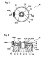
- FIG. 2 shows a view of the separately formed locking device 30 in the axial direction prior to installation in the transmission drive unit 10.
- the two locking elements 32 and 34, and the electromagnet 44 are arranged in the lock housing 52.
- the lock housing 52 is cylindrical in shape and has on its circumference radial locking elements 54, which cling to the housing 16 when installed in this.
- On the circumference of the Barrier housing 52 is arranged as an electrical contact 56 of the electromagnet 44, a plug element 58 which can be energized independently of the motor current of the electric motor 12.
- the front side of the lock housing 52 is formed as thrust washer 60, on which the first locking element 32 axially supported by axial extensions 62.
- the first blocking element 32 is designed as a disk with a central opening 64, which engages positively in a driver 66.
- the positive connection is formed in the exemplary embodiment by an internal toothing 68 of the first locking element 32, which is pushed axially onto an external toothing 70 of the driver 66.
- FIG. 3 shows a section according to III-III of the locking device 30 in FIG. 2 , wherein for the purpose of illustration, the driver 66 without drive shaft 14 is shown in positive engagement with the first blocking element 32.
- the first blocking element 32 has at its central opening 64 a sleeve 72 on which the internal toothing 68 is integrally formed.
- the locking element 32 For axial support against the inner wall of the thrust washer 60, the locking element 32 as axial extensions 62 on a circumferential ridge 63, which is supported on the rotationally fixed stop 74, which is formed by the inner wall of the thrust washer 60.
- the first blocking element 32 further axial extensions 62 which are formed as a latching hook 61 and through the central opening 64 of the thrust washer 60 therethrough, on the - another stop 74 forming - outer wall of the thrust washer 60 abut.
- the latching hooks 61 are freed from the sleeve 72, so that they can be flexibly inserted through the opening 64 and then engage securely. In this way, the first locking element 32 is reliably secured in a simple manner against axial displacement within the lock housing 52.
- the axial extensions 62 supported by material deformation on the outside of the thrust washer 60 or the axial extensions 62 are formed as a dome, which is supported by means of a clamping ring on the thrust washer 60.
- the electromagnet 44 is disposed on the bobbin 46, which simultaneously forms a part of the lock housing 52.
- the second blocking element 34 is arranged non-rotatably in the barrier housing 52 via axial guide elements 78, the guide elements 78 cooperating with corresponding counter-elements 80 of the barrier housing 52.
- the disk formed as a second locking element 34 is positively pressed by the return element 42 against the first locking element 32. If the electromagnet 44 is energized, the blocking element 34 by the magnetic force in FIG. 3 pulled down, whereby the positive connection 85 of the blocking state dissolves and the first locking element 32 can rotate smoothly relative to the second locking element 34.
- the return element 42 are formed, for example, as a plurality of spring elements 43 or as a central opening 64 enclosing the monolithic spring element 43.
- the blocking elements 32 and 34 each have radially extending depressions 82 and elevations 84, which are formed, for example, as axial toothing 85.
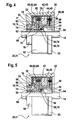
- FIG. 4 an example of a locking device 30 is shown installed in the housing 16 state, which does not belong to the invention.
- the electromagnet 44, the second blocking element 34 rotatably connected to the housing 16 and the first blocking element 32 rotatable by means of the drive shaft 14 are again arranged and together form the separately formed assembly 31, which is integrated into the housing as an assembly in a single assembly step 16 is inserted.
- the first and the second blocking element 32 and 34 engage axially with each other, wherein as a restoring element 42 for pressing the second locking element 34 individual spring elements 43 are arranged in corresponding receptacles of the bobbin 46.
- the recordings are simultaneously formed as axial guide elements 78, which engage in corresponding counter-elements 80 of the locking element 34.
- the torque in the blocking state can be derived from the first blocking element 32 to the second blocking element 34 via the coil carrier 46 and the barrier housing 52 onto the housing 16 of the transmission drive unit 10.
- electrically conductive spring elements 89 which extend in the axial direction, are arranged as electrical contacts 56 from an end face 88 of the electromagnet 44.
- a roller bearing 18 is designed as a floating bearing in the housing 16, which is rotatably connected to an outer ring 90 to the housing 16 and with a Inner ring 92, the drive shaft 14 receives.
- the housing 16 is, for example, injection-molded from aluminum.
- the roller bearing 18, which is designed as a ball bearing 19, in this case is inserted into a bearing receptacle 17 and secured by the resiliently against the outer ring 90 lock housing 52 together with this axially, for example. By caulking or pressing.
- the assembly 31 of the locking device 30 is disposed on the roller bearing 18 such that the first locking element 32 is axially supported on a stop 74, which is formed by the inner ring 92.
- the drive shaft 14 is inserted with the driver 66 through the central opening 64 of the locking device 30 and into the inner ring 92 until the first locking element 32 is axially supported on a further stop 74 of the drive shaft 14.
- This second stop 74 is formed in the example as a circumferential collar 94 of the driver 66.
- an axial spring 96 is arranged to compensate for an axial displacement of the drive shaft 14. Due to the bias of the axial spring 96, the positioning of the armature shaft 14 relative to the locking device 30 does not have to be very accurate, which considerably simplifies the assembly of the transmission drive unit 10.
- the reliable axial fixation of the rotatable locking element 32 is thereby also secured with minimal installation effort.
- the drive shaft 14 is mounted at least with another, not shown fixed bearing, wherein the axial clearance - caused by thermal expansion or material wear or assembly tolerances - is compensated by the elastic axial bearing of the first locking element 32.
- the power transmission from the drive shaft 14 to the first control element 32 in turn via a positive connection between the driver 66 and the locking disc 32, wherein no high precision requirements are placed on them.
- this has a collar 53 with a larger diameter, which forms an interference fit with the housing 16.
- FIG. 5 shows a variation of the example according to FIG. 4 in which the roller bearing 18 is formed as part of the locking device 30 on the lock housing 52.
- the lock housing 52 has for this purpose a receptacle 98 into which the outer ring 90 of the roller bearing 18 is pressed or rotatably secured in another known manner it.
- the rolling bearing 18 is part of the assembly 31 and can be inserted in an assembly step with the locking device 30 in the housing 16.
- the inner ring 92 a radial stop 74 for the first locking element 32, both of which rotate in rotation together with the drive shaft 14.
- the driver 66 is first pushed through the central opening 64 of the control element 32 and then through the inner ring 92.
- the driver 66 with the inner ring 92 forms a clearance fit and with the locking disc 32 a positive connection, for example.
- the locking elements 32 and 34 have, for example.
- the tolerances to this extent can be controlled by means of a prior Furtechnischs phenomenon in this designed as a separate, assembly 31 locking device 30 by, for example, the power requirement in the rotational state is measured.
- the electromagnet 44 in the example consists of a coil 45 which is wound on the coil carrier 46.
- the slotted support 46 is arranged on a yoke 47, against which the second non-rotatable locking element 34 in Drebschreib, when energized magnet 44, is applied.
- a gap of approximately 1 mm is created between the blocking element 34 and the yoke 47.
- the positive connection 85 between the two locking elements 32, 34 is formed as a flat or helical gearing 85 and has, for example, about 40 locking positions.
- Transmission drive unit (10) wherein the first, rotatable locking element (32) axially on the binenring (92) of the rolling bearing (18) is supported.
- Ciretriebe-Attriebsaku 10 wherein the first, rotatable blocking element (30) axially on the shaft (14) - in particular on a collar (94) of the driver (66) is supported.
- the transmission drive unit 10 is used to actuate a differential gear of a vehicle which, for example, is exposed to a vibratory load of 20 g.
- the locking device 30 according to the invention may also be used for other electric motors 12, e.g. Stellantriche be used, which are exposed to high temperature and Sehwingungsbelastung.
Landscapes
- Engineering & Computer Science (AREA)
- Power Engineering (AREA)
- Physics & Mathematics (AREA)
- Electromagnetism (AREA)
- Connection Of Motors, Electrical Generators, Mechanical Devices, And The Like (AREA)
- Gear Transmission (AREA)
Claims (14)
- Dispositif de verrouillage (30) pour bloquer un mouvement de rotation d'un arbre (14) par rapport à un boîtier (16) d'une unité d'entraînement à engrenage (10), comprenant un premier élément de verrouillage (32) et un deuxième élément de verrouillage (34) qui est déplaçable par rapport au premier élément de verrouillage (32) au moyen d'au moins un électroaimant (44) et d'au moins un élément de rappel (42), le dispositif de verrouillage (30) étant réalisé sous forme d'unité structurelle autonome (31) qui peut être montée sous forme d'unité (31) d'une part sur le boîtier (16) et d'autre part sur l'arbre (14), les deux éléments de verrouillage (32, 34) étant disposés avec l'électroaimant (44) et l'élément de rappel (42) à l'intérieur d'un boîtier de verrouillage (52),
caractérisé en ce que le boîtier de verrouillage (52) présente au moins une butée axiale (60, 74) sur laquelle s'appuie axialement le premier élément de verrouillage rotatif (32), afin que les deux éléments de verrouillage (32, 34) disposés dans le boîtier de verrouillage (52) ne soient pas axialement en contact dans l'état de rotation, le premier élément de verrouillage rotatif (32) présentant des saillies axiales (62, 61) qui s'appuient contre l'au moins une butée axiale (60, 74) du boîtier de verrouillage (52) et les éléments de verrouillage (32, 34) venant en prise par engagement par correspondance géométrique dans l'état de verrouillage dans la direction axiale. - Dispositif de verrouillage (30) selon la revendication 1, caractérisé en ce que les deux éléments de verrouillage (32, 34) présentent à chaque fois des renfoncements (82) s'étendant radialement et des rehaussements (84) s'étendant radialement, qui peuvent venir en prise les uns dans les autres par engagement par correspondance géométrique, afin de bloquer le mouvement de rotation de l'arbre (14).
- Dispositif de verrouillage (30) selon l'une quelconque des revendications 1 ou 2, caractérisé en ce que le boîtier de verrouillage (52) est réalisé sous forme pratiquement fermée, et peut être inséré dans le boîtier (16) de l'unité d'entraînement à engrenage (10).
- Dispositif de verrouillage (30) selon l'une quelconque des revendications précédentes, caractérisé en ce que le premier élément de verrouillage (32) est réalisé sous forme de disque rotatif avec des formations en saillie radiales (68) - par exemple une denture interne (68) - qui peuvent être engagées dans des formations en saillie conjuguées correspondantes (70) - par exemple une denture externe (70) - d'un dispositif d'entraînement (66) disposé de manière solidaire en rotation sur l'arbre (14), lequel dispositif d'entraînement est enfoncé dans l'élément de verrouillage (32) après le montage de ce dernier.
- Dispositif de verrouillage (30) selon l'une quelconque des revendications précédentes, caractérisé en ce que l'électroaimant (44) n'est pas alimenté en courant dans l'état de verrouillage, et le deuxième élément de verrouillage (34) est pressé par l'au moins un élément de rappel (42) par engagement par correspondance géométrique dans le premier élément de verrouillage (32), et dans l'état de rotation l'électroaimant (44) est alimenté en courant, afin de libérer le deuxième élément de verrouillage (34) axialement hors du premier élément de verrouillage (32).
- Dispositif de verrouillage (30) selon l'une quelconque des revendications précédentes, caractérisé en ce que l'au moins une butée axiale (74) est réalisée par la paroi extérieure d'un disque de butée (60).
- Dispositif de verrouillage (30) selon l'une quelconque des revendications précédentes, caractérisé en ce que pour le support axial par rapport à la paroi intérieure du disque de butée (60), l'élément de verrouillage (32) présente, en tant que saillies axiales (supplémentaires) (62), une nervure périphérique (63), qui s'appuie contre une butée fixée en rotation, qui est formée par la paroi intérieure du disque de butée (60).
- Dispositif de verrouillage (30) selon l'une quelconque des revendications précédentes, caractérisé en ce que les saillies (62, 61, 63) forment un crochet d'encliquetage (61) ou un goujon avec une bague de serrage ou de fixation, ou, après leur passage à travers le disque de butée (60) sont déformées radialement et s'appuient notamment au moyen d'une déformation de matériau contre le côté extérieur du disque de butée (60).
- Dispositif de verrouillage (30) selon l'une quelconque des revendications précédentes, caractérisé en ce que des éléments de ressort (89) sont disposés sur un côté frontal (88) de l'électroaimant (44) en tant que contact électrique (56), les éléments de ressort s'étendant dans la direction axiale.
- Dispositif de verrouillage (30) selon l'une quelconque des revendications précédentes, caractérisé en ce que l'électroaimant (44) est disposé dans un support de bobine (46) sur lequel sont façonnés, pour le guidage axial et/ou pour la fixation en rotation du deuxième élément de verrouillage (34), des éléments de guidage axiaux (78) - en particulier des tourillons (78) - qui viennent en prise dans des éléments conjugués correspondants (80) du deuxième élément de verrouillage (34).
- Dispositif de verrouillage (30) selon l'une quelconque des revendications précédentes, caractérisé en ce qu'au moins l'un des deux éléments de verrouillage (32, 34) - en particulier le deuxième élément de verrouillage (34) - est fabriqué au moins en partie en plastique, par exemple en un élastomère.
- Procédé de fabrication d'une unité d'entraînement à engrenage (10) avec un dispositif de verrouillage (30) selon l'une quelconque des revendications précédentes, caractérisé en ce que le dispositif de verrouillage (30) est fixé d'abord dans le boîtier (16) de l'unité d'entraînement à engrenage (10), et ensuite l'arbre (14) - en particulier avec le dispositif d'entraînement (66) - est introduit par engagement par correspondance géométrique avec jeu dans un évidement central (64) du premier élément de verrouillage (32).
- Procédé selon la revendication 12, caractérisé en ce que le dispositif de verrouillage (30) est incorporé de manière solidaire en rotation avec le boîtier de verrouillage (52) dans le boîtier (16) de l'unité d'entraînement à engrenage (10) et est fixé axialement en particulier au moyen d'une déformation de matériau.
- Procédé selon la revendication 12 ou 13, caractérisé en ce que le dispositif de verrouillage (30), avant l'incorporation dans le boîtier (16) et avant le montage de l'arbre (14) en tant qu'unité séparée (31) entourée par le boîtier de verrouillage (52) est contrôlé en termes de son fonctionnement, notamment de sa puissance absorbée.
Applications Claiming Priority (2)
| Application Number | Priority Date | Filing Date | Title |
|---|---|---|---|
| DE102004058096A DE102004058096A1 (de) | 2004-12-01 | 2004-12-01 | Sperrvorrichtung, sowie Getriebe-Antriebseinheit beinhaltend eine solche Sperrvorrichtung, sowie Verfahren zum Herstellen einer solchen Getriebe-Antriebseinheit |
| PCT/EP2005/055001 WO2006058803A1 (fr) | 2004-12-01 | 2005-10-05 | Dispositif de verrouillage, unite d'entrainement a engrenage comprenant un dispositif de verrouillage de ce type, et procede pour realiser une unite d'entrainement a engrenage de ce type |
Publications (2)
| Publication Number | Publication Date |
|---|---|
| EP1820251A1 EP1820251A1 (fr) | 2007-08-22 |
| EP1820251B1 true EP1820251B1 (fr) | 2013-05-08 |
Family
ID=35355722
Family Applications (1)
| Application Number | Title | Priority Date | Filing Date |
|---|---|---|---|
| EP05792060.5A Ceased EP1820251B1 (fr) | 2004-12-01 | 2005-10-05 | Dispositif de verrouillage, unite d'entrainement a engrenage comprenant un dispositif de verrouillage de ce type, et procede pour realiser une unite d'entrainement a engrenage de ce type |
Country Status (5)
| Country | Link |
|---|---|
| US (2) | US8746421B2 (fr) |
| EP (1) | EP1820251B1 (fr) |
| KR (1) | KR101175949B1 (fr) |
| DE (1) | DE102004058096A1 (fr) |
| WO (1) | WO2006058803A1 (fr) |
Cited By (1)
| Publication number | Priority date | Publication date | Assignee | Title |
|---|---|---|---|---|
| DE102025002027B3 (de) | 2025-06-13 | 2026-05-07 | Andreas Tatus | Antriebseinheit und Verfahren zum Betrieb |
Families Citing this family (11)
| Publication number | Priority date | Publication date | Assignee | Title |
|---|---|---|---|---|
| DE102007035790A1 (de) | 2007-07-31 | 2009-02-05 | Robert Bosch Gmbh | Sperrvorrichtung sowie Getriebe-Antriebs-Einheit |
| DE102007035748A1 (de) | 2007-07-31 | 2009-02-05 | Robert Bosch Gmbh | Sperrvorrichtung sowie Getriebe-Antriebs-Einheit |
| DE102007035789A1 (de) | 2007-07-31 | 2009-02-05 | Robert Bosch Gmbh | Sperrvorrichtung sowie Getriebe-Antriebs-Einheit |
| DE102015006040B4 (de) | 2014-05-10 | 2016-12-01 | Michael Werner | Rotor-Arretierungseinrichtung mit einem formschlüssigen Haltemoment |
| DE102015005360B3 (de) * | 2015-04-28 | 2016-06-23 | Sew-Eurodrive Gmbh & Co Kg | Getriebesystem |
| US9772029B2 (en) | 2015-07-09 | 2017-09-26 | Akebono Brake Industry Co., Ltd. | Planetary carrier with spring clutch |
| US10518761B2 (en) | 2016-07-01 | 2019-12-31 | Akebono Brake Industry Co., Ltd | Electric park brake with electromagnetic brake |
| DE102018120116B3 (de) * | 2018-08-17 | 2019-12-12 | Knorr-Bremse Gesellschaft Mit Beschränkter Haftung | Zahnhaltebremse für eine Tür für ein Fahrzeug und Verfahren zum Betreiben einer Zahnhaltebremse |
| DE102019211443B4 (de) * | 2019-07-31 | 2021-03-04 | Festo Se & Co. Kg | Drehantriebsvorrichtung und damit ausgestatteter Roboterarm eines Roboters |
| KR102766377B1 (ko) * | 2019-11-06 | 2025-02-13 | 에이치엘만도 주식회사 | 파킹 브레이크용 액츄에이터 |
| KR102766415B1 (ko) * | 2019-11-06 | 2025-02-13 | 에이치엘만도 주식회사 | 파킹 브레이크용 액츄에이터 |
Family Cites Families (14)
| Publication number | Priority date | Publication date | Assignee | Title |
|---|---|---|---|---|
| US2725123A (en) | 1952-05-19 | 1955-11-29 | Frank E Reuland | Magnetic brake |
| US3096863A (en) * | 1959-10-28 | 1963-07-09 | American Electronics | Clutch or brake employing cam action |
| US4445596A (en) * | 1981-09-08 | 1984-05-01 | Facet Enterprises, Inc. | Electromagnetically released spring applied friction brake with torque booster and driving force distributor |
| US4398110A (en) * | 1982-05-05 | 1983-08-09 | Westinghouse Electric Corp. | Harmonic electric actuator |
| US5080214A (en) * | 1990-06-29 | 1992-01-14 | Inertia Dynamics, Inc. | Electromagnetic clutch |
| US5121018A (en) * | 1991-03-04 | 1992-06-09 | Lucas Aerospace Power Equipment Corporation | Latching brake using permanent magnet |
| DE19733169B4 (de) * | 1997-07-31 | 2005-06-16 | Chr. Mayr Gmbh & Co. Kg | Elektromagnetisch gelüftete Reibungs-Sicherheitsbremse mit zwei unabhängigen Bremskreisen |
| EP0957565B1 (fr) | 1998-05-14 | 2003-09-17 | Sew-Eurodrive GmbH & Co. KG | Moteur électrique avec frein |
| US6459182B1 (en) * | 1998-05-14 | 2002-10-01 | Sew-Eurodrive Gmbh | Electric motor with brake |
| DE19851196A1 (de) * | 1998-11-06 | 2000-05-25 | Harting Kgaa | Elektromagnetisch betätigte Bremse |
| CA2347527C (fr) * | 2000-05-12 | 2005-04-12 | Auburn Gear, Inc. | Differentiel a glissement limite dote de freins en contact avec du fluide magnetorheologique |
| DE10103736C2 (de) | 2001-01-26 | 2003-05-08 | Lenze Drive Systems Gmbh | Elektromagnetisch lüftbare Federkraftbremse mit einem gegen einen Widerlagerflansch pressbaren Bremsrotor |
| DE10160847A1 (de) | 2001-12-12 | 2003-07-17 | Valeo Auto Electric Gmbh | Betätigungsvorrichtung, insbesondere zur Betätigung von Sperrdifferentialen von Fahrzeugen |
| DE10236372A1 (de) | 2002-08-02 | 2004-02-19 | Brose Fahrzeugteile Gmbh & Co. Kommanditgesellschaft, Coburg | Antriebsmotor für Verstelleinrichtungen in Kraftfahrzeugen |
-
2004
- 2004-12-01 DE DE102004058096A patent/DE102004058096A1/de not_active Ceased
-
2005
- 2005-10-05 EP EP05792060.5A patent/EP1820251B1/fr not_active Ceased
- 2005-10-05 KR KR1020077012448A patent/KR101175949B1/ko not_active Expired - Fee Related
- 2005-10-05 WO PCT/EP2005/055001 patent/WO2006058803A1/fr not_active Ceased
- 2005-10-05 US US10/591,896 patent/US8746421B2/en not_active Expired - Fee Related
-
2014
- 2014-03-10 US US14/202,096 patent/US9906095B2/en not_active Expired - Fee Related
Cited By (1)
| Publication number | Priority date | Publication date | Assignee | Title |
|---|---|---|---|---|
| DE102025002027B3 (de) | 2025-06-13 | 2026-05-07 | Andreas Tatus | Antriebseinheit und Verfahren zum Betrieb |
Also Published As
| Publication number | Publication date |
|---|---|
| US9906095B2 (en) | 2018-02-27 |
| US8746421B2 (en) | 2014-06-10 |
| KR101175949B1 (ko) | 2012-08-23 |
| KR20070089688A (ko) | 2007-08-31 |
| DE102004058096A1 (de) | 2006-06-08 |
| US20140182981A1 (en) | 2014-07-03 |
| US20070187193A1 (en) | 2007-08-16 |
| WO2006058803A1 (fr) | 2006-06-08 |
| EP1820251A1 (fr) | 2007-08-22 |
Similar Documents
| Publication | Publication Date | Title |
|---|---|---|
| EP1218646B1 (fr) | Unite d'actionnement pour un frein a disque a actionnement electromecanique | |
| EP0133527B1 (fr) | Dispositif pour la limitation du jeu axial d'un arbre à palier à contact lisse d'un entraînement moteur | |
| WO2010060725A1 (fr) | Frein à disque actionnable électromécaniquement pour véhicules automobiles | |
| EP3004679B1 (fr) | Frein à tambour à actionnement électrique | |
| DE102004022407B4 (de) | Getriebemotor mit Failsafe-Einrichtung | |
| EP1820251A1 (fr) | Dispositif de verrouillage, unite d'entrainement a engrenage comprenant un dispositif de verrouillage de ce type, et procede pour realiser une unite d'entrainement a engrenage de ce type | |
| WO2001021975A1 (fr) | Unite d'actionnement pour un frein a disque a actionnement electromecanique | |
| DE112022003313T5 (de) | Kupplungsaktuator und Verfahren zu dessen Herstellung | |
| WO2007036387A1 (fr) | Unite de transmission et d'entrainement a fixation de palier sans jeu axial, utilisee notamment pour deplacer une partie mobile dans une automobile | |
| DE102015017076A1 (de) | Elektrische Maschine, insbesondere Elektromotor für ein Kraftfahrzeug | |
| EP1320175A2 (fr) | Dispositif d'actionnement, notamment pour actionner le verouillage d'un différentiel dans des véhicules | |
| EP1320176B1 (fr) | Dispositif d'actionnement, notamment pour actionner le verouillage d'un différentiel dans des véhicules | |
| DE102022212689A1 (de) | Bremslastmesseinrichtung für eine elektrische Kraftfahrzeugradbremse, Herstellungsverfahren dazu und elektrische Kraftfahrzeugradbremse mit Bremslastmesseinrichtung | |
| DE102019201952A1 (de) | Parksperre | |
| EP1958314B1 (fr) | Dispositif de blocage, unité d entraînement à engrenage comprenant un tel dispositif de blocage et procédé pour fabriquer une telle unité d entraînement à engrenage | |
| EP1958315B1 (fr) | Dispositif de blocage, unité d entraînement à engrenage comprenant un tel dispositif de blocage et procédé pour fabriquer une telle unité d entraînement à engrenage | |
| DE102023210313A1 (de) | Elektromechanische bremse und fahrzeug | |
| EP4162590B1 (fr) | Procédé de fabrication d'un entraînement, présentant un moteur électrique pourvu d'un système de freinage et entraînement | |
| DE102019109734A1 (de) | Lagervorrichtung | |
| DE102023120719B4 (de) | Aktor mit Transportsicherung | |
| DE102019109735A1 (de) | Lagervorrichtung | |
| DE102024210016A1 (de) | Elektromagnetischer Aktor für ein elektromagnetisch aktuiertes Sperrdifferential, elektromagnetisch aktuiertes Sperrdifferential und Fahrzeug | |
| EP3802185B1 (fr) | Module hybride et système d'entraînement pour un véhicule à moteur et procédé de fabrication d'un tel module hybride | |
| DE102023200727A1 (de) | Rotorvorrichtung für einen Gleichstrommotor zum Betreiben einer bewegbaren Komponente in einem Fahrzeug | |
| WO2006032584A1 (fr) | Unite d'entrainement a engrenage comprenant un element de reglage |
Legal Events
| Date | Code | Title | Description |
|---|---|---|---|
| PUAI | Public reference made under article 153(3) epc to a published international application that has entered the european phase |
Free format text: ORIGINAL CODE: 0009012 |
|
| 17P | Request for examination filed |
Effective date: 20070702 |
|
| AK | Designated contracting states |
Kind code of ref document: A1 Designated state(s): CZ DE FR HU |
|
| DAX | Request for extension of the european patent (deleted) | ||
| RBV | Designated contracting states (corrected) |
Designated state(s): CZ DE FR HU |
|
| 17Q | First examination report despatched |
Effective date: 20090505 |
|
| REG | Reference to a national code |
Ref country code: DE Ref legal event code: R079 Ref document number: 502005013696 Country of ref document: DE Free format text: PREVIOUS MAIN CLASS: H02K0007100000 Ipc: H02K0007102000 |
|
| GRAP | Despatch of communication of intention to grant a patent |
Free format text: ORIGINAL CODE: EPIDOSNIGR1 |
|
| RIC1 | Information provided on ipc code assigned before grant |
Ipc: H02K 7/102 20060101AFI20130108BHEP Ipc: H02K 7/10 20060101ALI20130108BHEP |
|
| GRAS | Grant fee paid |
Free format text: ORIGINAL CODE: EPIDOSNIGR3 |
|
| GRAA | (expected) grant |
Free format text: ORIGINAL CODE: 0009210 |
|
| AK | Designated contracting states |
Kind code of ref document: B1 Designated state(s): CZ DE FR HU |
|
| REG | Reference to a national code |
Ref country code: DE Ref legal event code: R096 Ref document number: 502005013696 Country of ref document: DE Effective date: 20130704 |
|
| PG25 | Lapsed in a contracting state [announced via postgrant information from national office to epo] |
Ref country code: CZ Free format text: LAPSE BECAUSE OF FAILURE TO SUBMIT A TRANSLATION OF THE DESCRIPTION OR TO PAY THE FEE WITHIN THE PRESCRIBED TIME-LIMIT Effective date: 20130508 |
|
| PLBE | No opposition filed within time limit |
Free format text: ORIGINAL CODE: 0009261 |
|
| STAA | Information on the status of an ep patent application or granted ep patent |
Free format text: STATUS: NO OPPOSITION FILED WITHIN TIME LIMIT |
|
| 26N | No opposition filed |
Effective date: 20140211 |
|
| REG | Reference to a national code |
Ref country code: DE Ref legal event code: R097 Ref document number: 502005013696 Country of ref document: DE Effective date: 20140211 |
|
| PG25 | Lapsed in a contracting state [announced via postgrant information from national office to epo] |
Ref country code: HU Free format text: LAPSE BECAUSE OF FAILURE TO SUBMIT A TRANSLATION OF THE DESCRIPTION OR TO PAY THE FEE WITHIN THE PRESCRIBED TIME-LIMIT; INVALID AB INITIO Effective date: 20051005 |
|
| REG | Reference to a national code |
Ref country code: FR Ref legal event code: PLFP Year of fee payment: 11 |
|
| REG | Reference to a national code |
Ref country code: FR Ref legal event code: PLFP Year of fee payment: 12 |
|
| REG | Reference to a national code |
Ref country code: FR Ref legal event code: PLFP Year of fee payment: 13 |
|
| REG | Reference to a national code |
Ref country code: FR Ref legal event code: PLFP Year of fee payment: 14 |
|
| PGFP | Annual fee paid to national office [announced via postgrant information from national office to epo] |
Ref country code: DE Payment date: 20191212 Year of fee payment: 15 |
|
| PGFP | Annual fee paid to national office [announced via postgrant information from national office to epo] |
Ref country code: FR Payment date: 20191022 Year of fee payment: 15 |
|
| REG | Reference to a national code |
Ref country code: DE Ref legal event code: R119 Ref document number: 502005013696 Country of ref document: DE |
|
| PG25 | Lapsed in a contracting state [announced via postgrant information from national office to epo] |
Ref country code: DE Free format text: LAPSE BECAUSE OF NON-PAYMENT OF DUE FEES Effective date: 20210501 Ref country code: FR Free format text: LAPSE BECAUSE OF NON-PAYMENT OF DUE FEES Effective date: 20201031 |