EP1820462B1 - Clou intramédullaire comportant des éléments de matériau à mémoire de forme - Google Patents
Clou intramédullaire comportant des éléments de matériau à mémoire de forme Download PDFInfo
- Publication number
- EP1820462B1 EP1820462B1 EP07009998A EP07009998A EP1820462B1 EP 1820462 B1 EP1820462 B1 EP 1820462B1 EP 07009998 A EP07009998 A EP 07009998A EP 07009998 A EP07009998 A EP 07009998A EP 1820462 B1 EP1820462 B1 EP 1820462B1
- Authority
- EP
- European Patent Office
- Prior art keywords
- stem
- shape
- intramedullary nail
- nail
- elements
- Prior art date
- Legal status (The legal status is an assumption and is not a legal conclusion. Google has not performed a legal analysis and makes no representation as to the accuracy of the status listed.)
- Expired - Lifetime
Links
- 239000012781 shape memory material Substances 0.000 title claims description 12
- 210000000988 bone and bone Anatomy 0.000 claims description 60
- 238000003780 insertion Methods 0.000 claims description 21
- 230000037431 insertion Effects 0.000 claims description 21
- 239000011888 foil Substances 0.000 claims description 6
- 230000000903 blocking effect Effects 0.000 claims description 3
- 230000006870 function Effects 0.000 claims description 2
- 230000008901 benefit Effects 0.000 description 9
- 238000000034 method Methods 0.000 description 7
- 238000000605 extraction Methods 0.000 description 4
- 239000000463 material Substances 0.000 description 4
- 230000004913 activation Effects 0.000 description 3
- 238000005553 drilling Methods 0.000 description 3
- 210000000689 upper leg Anatomy 0.000 description 3
- 238000010438 heat treatment Methods 0.000 description 2
- 238000004519 manufacturing process Methods 0.000 description 2
- 230000004048 modification Effects 0.000 description 2
- 238000012986 modification Methods 0.000 description 2
- 210000002303 tibia Anatomy 0.000 description 2
- 230000007704 transition Effects 0.000 description 2
- 206010020649 Hyperkeratosis Diseases 0.000 description 1
- 238000010521 absorption reaction Methods 0.000 description 1
- 230000003213 activating effect Effects 0.000 description 1
- 210000003484 anatomy Anatomy 0.000 description 1
- 230000003466 anti-cipated effect Effects 0.000 description 1
- 238000005452 bending Methods 0.000 description 1
- 230000036760 body temperature Effects 0.000 description 1
- 230000008859 change Effects 0.000 description 1
- 238000001816 cooling Methods 0.000 description 1
- 230000001186 cumulative effect Effects 0.000 description 1
- 230000000694 effects Effects 0.000 description 1
- 230000007246 mechanism Effects 0.000 description 1
- 230000009467 reduction Effects 0.000 description 1
- 230000008929 regeneration Effects 0.000 description 1
- 238000011069 regeneration method Methods 0.000 description 1
- 230000002441 reversible effect Effects 0.000 description 1
- 239000007787 solid Substances 0.000 description 1
- 230000003019 stabilising effect Effects 0.000 description 1
- 238000010415 tidying Methods 0.000 description 1
Images


Classifications
-
- A—HUMAN NECESSITIES
- A61—MEDICAL OR VETERINARY SCIENCE; HYGIENE
- A61B—DIAGNOSIS; SURGERY; IDENTIFICATION
- A61B17/00—Surgical instruments, devices or methods
- A61B17/56—Surgical instruments or methods for treatment of bones or joints; Devices specially adapted therefor
- A61B17/58—Surgical instruments or methods for treatment of bones or joints; Devices specially adapted therefor for osteosynthesis, e.g. bone plates, screws or setting implements
- A61B17/68—Internal fixation devices, including fasteners and spinal fixators, even if a part thereof projects from the skin
- A61B17/72—Intramedullary devices, e.g. pins or nails
- A61B17/7233—Intramedullary devices, e.g. pins or nails with special means of locking the nail to the bone
- A61B17/7258—Intramedullary devices, e.g. pins or nails with special means of locking the nail to the bone with laterally expanding parts, e.g. for gripping the bone
- A61B17/7266—Intramedullary devices, e.g. pins or nails with special means of locking the nail to the bone with laterally expanding parts, e.g. for gripping the bone with fingers moving radially outwardly
-
- A—HUMAN NECESSITIES
- A61—MEDICAL OR VETERINARY SCIENCE; HYGIENE
- A61B—DIAGNOSIS; SURGERY; IDENTIFICATION
- A61B17/00—Surgical instruments, devices or methods
- A61B2017/00831—Material properties
- A61B2017/00867—Material properties shape memory effect
Definitions
- the present invention relates in its more general aspect to an intramedullary nail suitable for insertion in a fractured elongate bone according to the preamble of claim 1.
- the invention relates to an intramedullary nail suitable for insertion in a fractured elongate bone, such as a femur or a tibia, comprising a stem extending between a proximal end and a distal end.
- Intramedullary nails are known, which, during a surgical operation, are inserted in a fractured elongate bone and fixed therein, in order to reconstruct the original bone shape and in the meantime to recover the bone solidity, so that callus regeneration mechanisms can correctly occur.
- the stems of these intramedullary nails are generally of substantially cylindrical shape and they can be both solid and hollow.
- two or more offset holes are usually provided on the nail, having axes lying on parallel or crossing planes extending diametrically across the stem, in correspondence with the nail distal end, and two or more offset holes having the same size, having axes not necessarily lying on parallel planes, in correspondence with the nail proximal end.
- Said holes are suitable for housing bone screws, which are inserted, after a convenient bone drilling, in the bone, with the subsequent fixation of the intramedullary nail to the bone portions.
- intramedullary nails being structured as above schematically described have known drawbacks mainly occurring when bone drillings are to be performed for bone screw insertion. This step is particularly critical since it is known that a good nail fastening essentially depends on the correct realisation of these bone drillings, obviously made in correspondence with the holes of the inserted intramedullary nail.
- the precise location of the intramedullary nail holes is made difficult by the fact that the holes are no more visible, being the nail inserted in the bone. It is then worth underlining a further location problem, i.e the fact that the intramedullary nail can be, when being inserted, slightly bent, so that the holes at the nail distal end are no more, with respect to the proximal end, in the same position as before installing the nail.
- a nail according to the preamble of claim 1 is known for example from documents FR 2 727 304 and FR 2 783 702 .
- the problem underlying the present invention is to provide an intramedullary nail suitable for insertion in a fractured elongate bone, capable to meet the above-mentioned requirement, meanwhile overcoming, in a simple and effective way, all the drawbacks mentioned with reference to the prior art.
- the shape-memory elements are suitable to take a first shape, or configuration, wherein they are retractably housed in the respective seats of the stem and a second shape or configuration wherein they project from their respective seats.
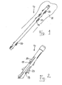
- an intramedullary nail according to the present invention is shown and globally indicated with 10, suitable for insertion in a fractured elongate bone 12, such as for example a femur or a tibia.
- the nail 10 comprises a stem 14 extending between a proximal end 16 and a distal end 18.
- the stem 14 is preferably composed of a cylindrical tubular body.
- the stem 14, according to an aspect of the present invention, comprises a plurality of elements 20 realised with at least a shape-memory material and a plurality of seats 19 formed in the stem 14 for housing the elements 20.
- the elements 20 are preferably similar to each other.
- the elements 20 are suitable to take a first shape, or configuration, wherein said elements 20 are retractably housed in the respective seats 19, so as to allow the insertion of the nail in the bone and a second shape or configuration wherein said elements 20 are projecting from the respective seats 19 for allowing the grip and the fixing in the fractured bone.
- Shape memory material means a material, already known in the technique, having a given starting shape and taking, under predetermined external conditions or undergoing a predetermined activation condition, after a so-called “material instruction” step, a given new shape.
- the starting shape corresponds to the second shape or configuration wherein the shape-memory elements are arranged projecting form the stem.
- the new shape, or first shape is taken by lowering the temperature of the nail.
- this new shape corresponds to the above first shape, or configuration, which is taken by the shape-memory elements 20 retractably arranged in the seats 19 of the nail 10.
- the nail 10 can be inserted in the bone.
- the shape-memory elements 20 take the starting shape again.
- the starting shape is the above second shape or configuration, wherein the nail is fixed to the bone by means of the elements 20 projecting from the stem 14.
- the particular characteristic of the shape-memory elements stays in that the taking of the second shape or configuration, i.e. the return to the starting shape, under determined physical conditions, continues until the "memorised" starting shape is reached.
- This characteristic ensures a constant push, or thrust, into the bone, also in case the bone should be reabsorbed for any reason losing its original shape and size.
- the expansion temperature of the shape-memory elements from the first to the second shape or configuration can be obtained by means of the body temperature in case a shape-memory material having a so called Af (i.e. end point of the transition while heating), which is lower than, or equal to, 37C° (e.g. 25C°) is used. In case of shape-memory materials having an Af around 48C° suitable heating tools are used.
- Af i.e. end point of the transition while heating
- 37C° e.g. 25C°
- shape-memory material Another characteristic of the shape-memory material stays in that the transition from the first to the second shape, or configuration, is reversible, i.e. the shape-memory elements can be transformed from the second to the first shape, or configuration, allowing the extraction of the nail from the bone.
- the nail 10 comprises a stem 14 having a diameter preferably in the range of 7 to 12 mm.
- a threading 16a is made ( figure 9 ) for a threaded connection with a suitable driving tool 13 for gripping the nail.
- a suitable driving tool 13 for gripping the nail.
- grooves 16b are also present.
- the tip portion of the stem 14 is preferably rounded so as to allow a sliding of the nail in the medullary channel.
- the stem 14 is substantially straight. However, according to the anatomic needs of the elongate bone, the stem 14 can be curved, or bent so that the proximal end 16 forms angle with the distal end 18.
- the stem 14 is also of the cannulated type and it is preferably made of a cylindrical tubular body.
- the stem 14 is also provided with transversal holes 14d for the insertion of pins suitable to avoid a torsion of the nail in the bone.
- the stem 14 comprises a plurality of transversal slots 19, or elongate holes, also called openings, which extend passing from one side of the stem 14 to the other.
- the slots 19 serve as seat for housing the shape-memory elements 20.
- each transversal slot 19 forms a pair of elongate holes which are realised on opposite walls of the stem 14.
- these opposite elongate holes will be considered as a single transversal slot 19 ( figure 7 ), which defines the seat where a corresponding element 20 realised with shape-memory material is housed.
- the shape-memory elements 20 form inserts 23, structurally independent from the stem 14, and suitable to be inserted in the transversal slots 19.
- the stem 14 is made of two united half-cylinders, for example welded, along the length.
- the inserts 23 are preferably inserted fixedly or by pressure in the respective slots 19.
- each insert 23 comprises a pair of elements 20.
- the elements 20 forming the above pair are connected to each other by means of a connection central element 22.
- An insert 23 is thus obtained having substantially fork-like shape.
- the fork is symmetrical and it has an upturned V or U-like shape. The symmetry of the fork allows to obtain a balanced push onto the bone.
- the fork-like insert 23 is suitable to be housed in the corresponding transversal slot 19, so that the two elements 20 forming the above pair are arranged on the opposite sides of the stem 14.
- each insert 23 is provided with two shape-memory elements 20.
- the plurality of inserts 23 is distributed on the side surface of the stem 14 in correspondence with the proximal end 16 and with the distal end 18. In this way the central portion of the stem 14 has a substantially smooth surface.
- the distal portion 18 comprises two inserts 23, whereas the proximal portion 16 comprises three inserts 23.
- the inserts 23 are arranged as offset with one another, for example they are arranged with a offset of sexagesimal 90°.
- the offset arrangement ensures a determined stability on orthogonal planes.
- the two elements 20 forming the pair of each insert 23 consist of two opposite elongate tabs or fillets 20. According to the invention, when the nail 10 is in the first shape or configuration and is inserted in the bone, the tabs 20 are substantially aligned with the connection body 22 so as to retractably lie in the slots 19.
- the tabs 20 are wide apart with respect to the connection body 22 so that the free ends 21 of the tabs 20 are projecting from the slots 19.
- the tabs 20 have a flexural memory.
- the tabs 20 have a thickness equal to the connection body 22, so as to obtain an insert 23 having a uniform thickness.
- the tabs 20, on the surface facing outwards from the stem 14, also have a substantially sawtooth-like profile 32 for improving the grip of the tab 20 with the bone.
- the length of the tabs 20 can vary according to the position of the nail with respect to the distal 18 or proximal 16 portion, and according to the treated bone.
- the tabs 20, in the distal portion 18, nearer the tip of the nail 10 and, respectively in the proximal portion 16, nearer the head of the nail 10, are longer than the tabs arranged in the central area of the stem 14.
- the insert 23 is provided with a hole 25 on the connection body 22.
- the hole 25 is coaxial to the axial hole of the stem 14 and it allows the insertion of a guide wire, such as for example a Kirschner wire.
- each insert 23 is of the multilaminar type, i.e. it is realised by means of a plurality of metallic foils being overlapped and welded one on the other.
- the insert 23 is provided with a pair of blocking pins 33 inserted transversally to the metallic foils.
- the use of blocking pins is provided also for tidying the insert 23 on the stem 14 once it is arranged inside the seat 19.
- the nail 10 comprises, as connection element, a cylindrical sleeve 26 for the connection with the two shape-memory elements 20.
- two opposite grooves 28 are also provided on the cylindrical sleeve 26, being substantially offset of a straight angle with respect to said two tabs 20 and suitable to house at least partially the tabs of a cylinder 26 flanked along the stem axis. In this way, the sleeves 32 are overlapped with respect to each other.
- the profile of the tabs 20 is tapered towards the free end 21.
- a section is provided with an inclined surface 30 which leads to a thinning of the tab thickness in correspondence with the section towards the free end 21.
- the nail 10 comprises a sheathing tubular jacket 40 ( figures 12 , 14 , 15a-15d ) wherein the stem 14 is inserted.
- the sheathing jacket 40 is described with reference to the nail 10 of figures 1-15 .
- the jacket 40 has a substantially tubular shape and it has the function of retaining, according to the need, the shape-memory elements 20 in the first shape, i.e. in the closed retractable position in the slots 19, as shown in figure 14 .
- the jacket 40 allows to firmly maintain the shape-memory elements 20 in the seats 19, before the nail 10 is inserted in the bone and until it is inserted in the medullary channel.
- the jacket 40 particularly comprises a side wall 41 and a plurality of transversal elongate holes 42, made in the tubular wall 41.
- the jacket 40 and the stem 14 can be shifted with respect to each other between a first operative position during which the side wall 41 closes at least partially the shape-memory elements 20 in the first retractable shape in the seats 19, and a second operative position wherein the transversal elongate holes 42 of the jacket 40 are aligned with the slots 19 of the stem 14, so as to allow the taking of the second shape by the elements 20, and thus their widening apart outside the slots 19.
- the shift relative to the jacket 40 with respect to the stem 14 occurs along the axis of the nail 10.
- the above shift is obtained by means of a suitable driving tool.
- the driving tool is configured to shift the stem 14 with respect to the jacket 40.
- the nail 10 is provided with a so called double-threading system ( figures 14a and 14b ).
- a first threading is the above-mentioned threading 16a of the nail 10 head.
- this first threading 16a a control screw 45 ( figure 14c ) provided with relative threading 45a is intended to be screwed.
- a second threading 66a is made in a cylindrical body 66 ( figure 14a and 14b ) welded on the head portion of the jacket 40.
- the cylindrical body 66 is provided with a pair of recesses 68, which are intended to receive corresponding teeth 55 of a bearing sleeve 54.
- the bearing sleeve 54 allows to maintain the jacket 40 axially firm during the shift of the nail 10.
- a tube 50 provided with relative threading 50b is screwed, being inserted in the bearing sleeve 54.
- the tube 50 is internally hollow to blacklash-like house inside the above control screw 45.
- figure 14B shows the tube 50 housed in the bearing sleeve 54a and firmly screwed in the second threading 66a.
- Figure 14C shows the control screw 45 inserted in the tube 50 and firmly screwed in the first threading 16a of the nail 10.
- a clockwise rotation of the control screw 45 determines a setting back of the nail 10 ( figure 15a ), whereas a counter-clockwise rotation causes an advance of the nail 10 ( figure 15b ).
- control screw 45 is screwed, for example clockwise, determining an axial setting back of this latter ( figure 15a ).
- the jacket 40 is firmly kept by the bearing body 54 and by the tube 50.
- This operation is performed when the nail is at low temperatures and the material is instructed to take the first shape or configuration ( figure 15b ).
- the tabs 20 can be freed from the tie exerted by the jacket 40 for allowing to take of the second shape or configuration, i.e. the one projecting from the slots 19 ( figure 15d ).
- control screw 45 is rotated counter-clockwise with respect to the tube 50.
- the nail 10 is axially advanced with respect to the jacket 40, until a complete alignment of the elongate holes 41 and of the slots 19 of the nail is obtained.
- the bearing body 54, the tube 50 and the control screw 45 can be removed.
- the method described up to now can be performed in an inverted way during an extraction step of the nail 10 from the bone.
- the inserts 23 can be cooled for example, by inserting a cooling element in the stem, so as to allow the retractably positioning of the elements 20 in the seats 19.
- the nail 10 can be removed from the bone with a minimum invasiveness.
- An application method of said intramedullary nail in said elongate bone comprises:
- the nail 10 is positioned in said elongate bone 12, in the initial shape thereof, with the free ends 21 of the elements 20 substantially not projecting from the side surface of the stem 14.
- said shape-memory elements 20 are activated, so that the free ends 21 tend to be projected outwards the stem 14, with a subsequent interference of these free ends 21 with respect to the bone portion surrounding said stem 14: this interference causes in practise a grip, solidly fixing said nail 10 in the bone 12.
- inserts 23 are fixed alternatively with respect to each other not to create a torsion or rotation effect when stabilising the nail 10 on the bone 12.
- the stem 14 is preferably a cylindrical tubular body: the central hole serves to have an improved thermal exchange, helping thus in activating the elements 20.
- a nail offering a minimum invasiveness is thud obtained for being inserted.
- a further advantage of the intramedullary nail according to the present invention is that of being of simple production, thanks to the reduced number of different pieces. It is to be noted in fact that, as above described, the inserts are similar.
- Another advantage of the present invention stays in that the nail comprises a plurality of shape-memory inserts, which can be easily inserted in the stem.
- the stem realised with the two half-cylinders is particularly advantageous for allowing the insertion of the inserts 23.
- shape-memory inserts stays in that they are structurally independent from the nail stem. This allows to realise a stem of a non shape-memory material with substantial reduction of the production cost.
- the insertion by pressure of the inserts in the slots has the advantage of realising an easy connection of the inserts with the nail stem, avoiding possible welds.
- Another advantage of the present invention stays in that the taking of the first and of the second shape by the elements 20 is facilitated by the use of the sheathing jacket.
- the jacket in fact allows maintaining the memory elements in the retractable position during the insertion in the medullary channel, for avoiding the risk that the body heat determines a shape variation before the nail is completely arranged in the bone.
- a further advantage of the tubular jacket also stays in that it facilitates the extraction of the nail from the bone.
Landscapes
- Health & Medical Sciences (AREA)
- Orthopedic Medicine & Surgery (AREA)
- Surgery (AREA)
- Life Sciences & Earth Sciences (AREA)
- Heart & Thoracic Surgery (AREA)
- Nuclear Medicine, Radiotherapy & Molecular Imaging (AREA)
- Engineering & Computer Science (AREA)
- Biomedical Technology (AREA)
- Neurology (AREA)
- Medical Informatics (AREA)
- Molecular Biology (AREA)
- Animal Behavior & Ethology (AREA)
- General Health & Medical Sciences (AREA)
- Public Health (AREA)
- Veterinary Medicine (AREA)
- Surgical Instruments (AREA)
- Prostheses (AREA)
Claims (21)
- Clou intramédullaire (10) approprié pour être inséré dans un os allongé fracturé (12) comprenant une tige (14) s'étendant entre une extrémité proximale (16) et une extrémité distale (18), une pluralité d'éléments (20) qui sont faits d'au moins un matériau à mémoire de forme, et une pluralité de sièges (19) formés dans la tige (14) pour loger lesdits éléments (20), où lesdits éléments (20) sont appropriés pour prendre une première forme, dans laquelle ils sont logés de manière rétractable dans les sièges respectifs (19), et une deuxième forme, dans laquelle ils dépassent des sièges respectifs (19), et où le clou comprend des éléments rapportés (23) structurellement indépendants de la tige (14), et comprenant au moins l'un desdits éléments à mémoire de forme (20), chacun desdits éléments rapportés (23) étant approprié pour être inséré dans un siège correspondant (19), caractérisé en ce que chaque élément rapporté est du type multi-stratifié, c'est-à-dire qu'il est réalisé au moyen d'une pluralité de feuilles qui se chevauchent du matériau à mémoire de forme.
- Clou intramédullaire (10) selon la revendication 1, caractérisé en ce que les sièges de la tige (14) sont faits d'une pluralité de fentes transversales, ou de trous allongés (19), qui s'étendent en passant d'un premier côté de la tige (14) à l'autre côté.
- Clou intramédullaire (10) selon les revendications 1 ou 2, caractérisé en ce que la tige est faite de deux demi-cylindres réunis le long de la longueur.
- Clou intramédullaire (10) selon la revendication 1, caractérisé en ce que chaque élément rapporté (23) est inséré par pression dans le siège respectif (19).
- Clou intramédullaire (10) selon la revendication 1, caractérisé en ce que chacun desdits éléments rapportés (23) comprend deux éléments à mémoire de forme (20), qui sont reliés au moyen d'un élément de liaison central (22, 26).
- Clou intramédullaire (10) selon la revendication 5, caractérisé en ce que chaque élément rapporté (23) a sensiblement une forme de fourche.
- Clou intramédullaire (10) selon la revendication 1, caractérisé en ce que pour assurer un assemblage stable des feuilles métalliques, la pièce rapportée (23) est pourvue d'une paire de goupilles de blocage (33) insérée transversalement aux feuilles métalliques.
- Clou intramédullaire (10) selon les revendications 2 et 6, caractérisé en ce que chaque élément rapporté en forme de fourche (23) est approprié pour être logé dans une fente transversale correspondante (19), de sorte que les deux éléments (20) sont agencés sur les côtés opposés de la tige (14).
- Clou intramédullaire (10) selon la revendication 1, caractérisé en ce que les éléments rapportés (23) sont disposés à la suite sur la longueur de la tige (14).
- Clou intramédullaire (10) selon la revendication 1, caractérisé en ce que les éléments rapportés (23) sont répartis sur la surface latérale de la tige (14) en correspondance avec l'extrémité proximale (16) et l'extrémité distale (18).
- Clou intramédullaire (10) selon la revendication 8, caractérisé en ce que les éléments rapportés (23) sont décalés les uns par rapport aux autres de 90° en système sexagésimal.
- Clou intramédullaire (10) selon la revendication 5, caractérisé en ce que les deux éléments (20) de chaque élément rapporté (23) comprennent deux pattes opposées (20), qui présentent une mémoire en flexion.
- Clou intramédullaire (10) selon la revendication 5, caractérisé en ce que les deux éléments à mémoire de forme (20) de l'élément rapporté (23) sont reliés au moyen d'un manchon cylindrique (26).
- Clou intramédullaire (10) selon la revendication 13, caractérisé en ce que, sur ledit manchon cylindrique (26), deux rainures opposées (28) sont prévues, qui sont décalées pratiquement d'un angle droit par rapport auxdits deux éléments (20) et convenant pour loger au moins partiellement les éléments d'un manchon cylindrique disposé (26).
- Clou intramédullaire (10) selon la revendication 12, caractérisé en ce que les pattes (20) sur la surface qui est tournée vers l'extérieur de la tige (14) présentent un profil sensiblement en dents de scie (32).
- Clou intramédullaire (10) selon la revendication 1, caractérisé en ce qu'il comprend une chemise tubulaire (40) destinée à gainer la tige (14), en ayant la fonction de retenir les éléments à mémoire de forme (20) dans la première forme, c'est-à-dire dans la position rétractable fermée dans les sièges (19).
- Clou intramédullaire (10) selon la revendication 16, caractérisé en ce que la chemise (40) comprend une paroi latérale (41) et une pluralité de trous allongés transversaux (42), réalisés sur la paroi latérale (41).
- Clou intramédullaire (10) selon la revendication 17, caractérisé en ce que la chemise (40) et la tige (14) peuvent être décalées l'une par rapport à l'autre à partir d'une première position fonctionnelle, durant laquelle la paroi latérale (41) de la chemise (40) retient les éléments à mémoire de forme (20) dans la première forme rétractable dans les sièges (19), et une deuxième position fonctionnelle dans laquelle les trous transversaux (42) de la chemise (40) sont alignés sur les sièges (19) de la tige (14), de manière à permettre l'agencement des éléments (20) qui dépassent des sièges respectifs (19).
- Clou intramédullaire (10) selon la revendication 18, caractérisé en ce que le déplacement de la tige par rapport à la chemise (40) se produit le long de l'axe du clou (10).
- Clou intramédullaire (10) selon la revendication 19, caractérisé en ce qu'il comprend une vis de commande (45), appropriée pour être reliée de manière rigide à une partie de tête (14a) de la tige (14) pour commander, au moyen d'une rotation autour de son propre axe, le déplacement axial de la tige (14) par rapport à la chemise (40).
- Clou intramédullaire (10) selon la revendication 20, caractérisé en ce qu'il comprend un tube creux à l'intérieur (50) approprié pour être relié de manière rigide à une partie de tête de la chemise (40) et dans lequel la vis de commande (45) est logée avec un jeu.
Priority Applications (1)
| Application Number | Priority Date | Filing Date | Title |
|---|---|---|---|
| EP07009998A EP1820462B1 (fr) | 2004-03-31 | 2005-03-31 | Clou intramédullaire comportant des éléments de matériau à mémoire de forme |
Applications Claiming Priority (4)
| Application Number | Priority Date | Filing Date | Title |
|---|---|---|---|
| EP04007786A EP1582160A1 (fr) | 2004-03-31 | 2004-03-31 | Clou intramedullaire comprennant des éléments de forme mémoire |
| EP04007785A EP1582159A1 (fr) | 2004-03-31 | 2004-03-31 | Clou intramedullaire avec des moyens d'expansion pour fixation dans l'os |
| EP07009998A EP1820462B1 (fr) | 2004-03-31 | 2005-03-31 | Clou intramédullaire comportant des éléments de matériau à mémoire de forme |
| EP05734396A EP1740113B1 (fr) | 2004-03-31 | 2005-03-31 | Clou intramedullaire avec des moyens d'expansion pour fixation dans l'os |
Related Parent Applications (2)
| Application Number | Title | Priority Date | Filing Date |
|---|---|---|---|
| EP05734396A Division EP1740113B1 (fr) | 2004-03-31 | 2005-03-31 | Clou intramedullaire avec des moyens d'expansion pour fixation dans l'os |
| EP05734396.4 Division | 2005-03-31 |
Publications (2)
| Publication Number | Publication Date |
|---|---|
| EP1820462A1 EP1820462A1 (fr) | 2007-08-22 |
| EP1820462B1 true EP1820462B1 (fr) | 2011-09-07 |
Family
ID=34965402
Family Applications (3)
| Application Number | Title | Priority Date | Filing Date |
|---|---|---|---|
| EP05734396A Expired - Lifetime EP1740113B1 (fr) | 2004-03-31 | 2005-03-31 | Clou intramedullaire avec des moyens d'expansion pour fixation dans l'os |
| EP07009999A Expired - Lifetime EP1815813B1 (fr) | 2004-03-31 | 2005-03-31 | Clou intramedullaire avec des moyens d'expansion pour fixation dans l'os |
| EP07009998A Expired - Lifetime EP1820462B1 (fr) | 2004-03-31 | 2005-03-31 | Clou intramédullaire comportant des éléments de matériau à mémoire de forme |
Family Applications Before (2)
| Application Number | Title | Priority Date | Filing Date |
|---|---|---|---|
| EP05734396A Expired - Lifetime EP1740113B1 (fr) | 2004-03-31 | 2005-03-31 | Clou intramedullaire avec des moyens d'expansion pour fixation dans l'os |
| EP07009999A Expired - Lifetime EP1815813B1 (fr) | 2004-03-31 | 2005-03-31 | Clou intramedullaire avec des moyens d'expansion pour fixation dans l'os |
Country Status (15)
| Country | Link |
|---|---|
| US (1) | US8162942B2 (fr) |
| EP (3) | EP1740113B1 (fr) |
| JP (3) | JP4809326B2 (fr) |
| AR (1) | AR054661A1 (fr) |
| AT (3) | ATE523154T1 (fr) |
| AU (3) | AU2005229558B2 (fr) |
| BR (1) | BRPI0509378A (fr) |
| CA (1) | CA2561155C (fr) |
| CR (1) | CR8719A (fr) |
| DE (1) | DE602005013074D1 (fr) |
| DK (2) | DK1820462T3 (fr) |
| ES (3) | ES2323273T3 (fr) |
| IL (3) | IL178285A0 (fr) |
| MX (1) | MXPA06011261A (fr) |
| WO (1) | WO2005094706A1 (fr) |
Cited By (3)
| Publication number | Priority date | Publication date | Assignee | Title |
|---|---|---|---|---|
| US8128627B2 (en) | 2007-03-22 | 2012-03-06 | Sonoma Orthopedic Products, Inc. | Segmented intramedullary system and apparatus |
| US9445805B2 (en) | 2009-11-16 | 2016-09-20 | Tornier, Inc. | Bone implant with convertible suture attachment |
| US9539001B2 (en) | 2006-03-22 | 2017-01-10 | Tornier, Inc. | Bone anchor installer and method of use |
Families Citing this family (85)
| Publication number | Priority date | Publication date | Assignee | Title |
|---|---|---|---|---|
| US20060282081A1 (en) | 2004-04-16 | 2006-12-14 | Fanton Gary S | Apparatus and method for securing tissue to bone with a suture |
| FR2884406B1 (fr) | 2005-04-14 | 2008-10-17 | Memometal Technologies Soc Par | Dispositif d'osteosynthese intramedullaire de deux parties d'os, notamment de la main et/ou du pied |
| US9060820B2 (en) | 2005-05-18 | 2015-06-23 | Sonoma Orthopedic Products, Inc. | Segmented intramedullary fracture fixation devices and methods |
| US8961516B2 (en) | 2005-05-18 | 2015-02-24 | Sonoma Orthopedic Products, Inc. | Straight intramedullary fracture fixation devices and methods |
| US8568413B2 (en) | 2008-12-18 | 2013-10-29 | Sonoma Orthopedic Products, Inc. | Bone fixation device, tools and methods |
| WO2006124764A1 (fr) * | 2005-05-18 | 2006-11-23 | Sonoma Orthopedic Products, Inc. | Dispositifs de fixation des os a effraction minimale, systemes et methodes d'utilisation |
| US8133226B2 (en) * | 2005-07-12 | 2012-03-13 | Nanyang Technological University | Intramedullary fixation device for fractures |
| US8998923B2 (en) | 2005-08-31 | 2015-04-07 | Spinealign Medical, Inc. | Threaded bone filling material plunger |
| US9155574B2 (en) | 2006-05-17 | 2015-10-13 | Sonoma Orthopedic Products, Inc. | Bone fixation device, tools and methods |
| EP1905367A1 (fr) * | 2006-09-28 | 2008-04-02 | Orthofix S.r.l. | Moyen d'ostéosynthèse intramédullaire |
| GB2442706A (en) * | 2006-10-09 | 2008-04-16 | Mohamed Khalid | An intramedullary rod for the fixation of bone fractures |
| WO2008064346A2 (fr) * | 2006-11-22 | 2008-05-29 | Sonoma Orthopedic Products, Inc. | Dispositif, outils et procédés de fixation de fracture |
| EP2120753B1 (fr) | 2007-03-05 | 2022-09-28 | Tornier, Inc. | SYSTÈMES D'AGRAFAGE et D'ANCRAGE |
| FR2913876B1 (fr) | 2007-03-20 | 2009-06-05 | Memometal Technologies Soc Par | Dispositif d'osteosynthese |
| WO2009009772A1 (fr) * | 2007-07-11 | 2009-01-15 | Sonoma Orthopedic Products, Inc. | Dispositifs de fixation de fracture et procédés d'incorporation d'une membrane |
| US8632543B2 (en) | 2007-09-28 | 2014-01-21 | Biomet C.V. | Composite intramedullary nail |
| EP2249718B1 (fr) | 2008-01-14 | 2019-09-18 | Conventus Orthopaedics, Inc. | Appareil de réparation des fractures |
| ITVI20080046A1 (it) * | 2008-02-27 | 2009-08-28 | Delta System Srl | Dispositivo per la riduzione di una frattura ossea |
| EP2299917A1 (fr) | 2008-06-10 | 2011-03-30 | Sonoma Orthopedic Products, Inc. | Dispositif de fixation de fracture, outils et procédés afférents |
| EP2133034B1 (fr) * | 2008-06-13 | 2011-12-28 | Orthofix S.r.l. | Broche intramédullaire à insérer dans un os long fracturé |
| FR2935601B1 (fr) | 2008-09-09 | 2010-10-01 | Memometal Technologies | Implant intramedullaire resorbable entre deux os ou deux fragments osseux |
| US8523902B2 (en) | 2009-01-30 | 2013-09-03 | Kfx Medical Corporation | System and method for attaching soft tissue to bone |
| US8012155B2 (en) * | 2009-04-02 | 2011-09-06 | Zimmer, Inc. | Apparatus and method for prophylactic hip fixation |
| EP2298201A1 (fr) * | 2009-08-31 | 2011-03-23 | Ozics Oy | Agencement pour support d'os interne |
| KR101058795B1 (ko) | 2009-08-31 | 2011-08-23 | 김민석 | 척추 고정용 나사 |
| US8545499B2 (en) * | 2009-09-28 | 2013-10-01 | Zimmer, Inc. | Expandable intramedullary rod |
| ES3036690T3 (en) | 2009-10-13 | 2025-09-23 | Conmed Corp | System for securing tissue to bone |
| US20110087291A1 (en) * | 2009-10-14 | 2011-04-14 | Warsaw Orthopedic, Inc. | Fusion implants and systems for posterior lateral procedures |
| US9078707B2 (en) | 2009-12-01 | 2015-07-14 | Osteomed Llc | Polyaxial facet fixation screw system with cannula inserter |
| WO2011088172A1 (fr) | 2010-01-15 | 2011-07-21 | Brenzel Michael P | Tige orthopédique tournante rigide |
| CN102821707B (zh) | 2010-01-20 | 2016-02-03 | 康文图斯整形外科公司 | 用于骨接近和骨腔准备的装置及方法 |
| CN108125714A (zh) | 2010-03-08 | 2018-06-08 | 康文图斯整形外科公司 | 用于固定骨植入物的装置及方法 |
| WO2011145091A1 (fr) * | 2010-05-17 | 2011-11-24 | I.B.I. Israel Biomedical Innovations Ltd. | Dispositif chirurgical d'attache équipé de moyen de retenue de tulle |
| US9072564B2 (en) | 2010-06-02 | 2015-07-07 | Wright Medical Technology, Inc. | Hammer toe implant and method |
| US8608785B2 (en) | 2010-06-02 | 2013-12-17 | Wright Medical Technology, Inc. | Hammer toe implant with expansion portion for retrograde approach |
| US9498273B2 (en) | 2010-06-02 | 2016-11-22 | Wright Medical Technology, Inc. | Orthopedic implant kit |
| US9724140B2 (en) | 2010-06-02 | 2017-08-08 | Wright Medical Technology, Inc. | Tapered, cylindrical cruciform hammer toe implant and method |
| WO2011163402A1 (fr) | 2010-06-22 | 2011-12-29 | Osteomed, Lp | Système de vis de fixation de facette polyaxial avec augmentation de fixation |
| WO2012010184A1 (fr) * | 2010-07-22 | 2012-01-26 | Norman Zschech | Clou médullaire |
| US20220304814A1 (en) * | 2010-07-27 | 2022-09-29 | Tenon Medical, Inc. | Prostheses for Stabilizing Bone Structures |
| CN101953709A (zh) * | 2010-09-29 | 2011-01-26 | 上海交通大学医学院附属第三人民医院 | 可吸收肋骨髓内钉 |
| US8834483B2 (en) | 2010-10-04 | 2014-09-16 | Biomedical Enterprises, Inc. | Method and system for storing and inserting an implant |
| US9044313B2 (en) * | 2010-10-08 | 2015-06-02 | Kfx Medical Corporation | System and method for securing tissue to bone |
| EP2471477A1 (fr) | 2010-12-31 | 2012-07-04 | ORTHOFIX S.r.l. | Clou intramédullaire avec éléments de mémoire de forme |
| EP2471478A1 (fr) * | 2010-12-31 | 2012-07-04 | ORTHOFIX S.r.l. | Clou intramédullaire avec éléments de mémoire de forme pour os longs |
| ES2873024T3 (es) | 2011-04-13 | 2021-11-03 | Conmed Corp | Sistema de fijación de tejido a hueso |
| US8652136B2 (en) * | 2011-08-15 | 2014-02-18 | Zimmer, Gmbh | Femoral fracture fixation device |
| US9775597B2 (en) | 2011-10-04 | 2017-10-03 | Conmed Corporation | Dual expansion anchor |
| CA2860301C (fr) | 2012-01-15 | 2019-04-23 | Triticum Ltd. | Dispositif et methode d'elimination d'occlusions dans un vaisseau biologique |
| US9532881B2 (en) * | 2012-08-12 | 2017-01-03 | Brian Albert Hauck | Memory material implant system and methods of use |
| US8945232B2 (en) | 2012-12-31 | 2015-02-03 | Wright Medical Technology, Inc. | Ball and socket implants for correction of hammer toes and claw toes |
| WO2014159058A1 (fr) | 2013-03-14 | 2014-10-02 | Kfx Medical Corporation | Ancrage osseux à capture tissulaire |
| AU2014237579B2 (en) | 2013-03-15 | 2019-03-14 | Conmed Corporation | System and method for securing tissue to bone |
| US10016192B2 (en) | 2013-06-14 | 2018-07-10 | Tornier, Inc. | Suture for connecting a human or animal tissue, soft anchor and method for attaching a tissue to a bone |
| US9522022B2 (en) * | 2013-11-18 | 2016-12-20 | Biomedical Enterprises, Inc. | Method and appparatus for an intramedullary implant and method of implantation therefor |
| US9636155B2 (en) | 2013-11-18 | 2017-05-02 | Biomedical Enterprises, Inc. | Method and apparatus for an intramudullary implant and method of implantation thereof |
| US9474561B2 (en) | 2013-11-19 | 2016-10-25 | Wright Medical Technology, Inc. | Two-wire technique for installing hammertoe implant |
| CA2969316A1 (fr) | 2013-12-12 | 2015-06-18 | Conventus Orthopaedics, Inc. | Outils et methodes de deplacement de tissu |
| US9770278B2 (en) | 2014-01-17 | 2017-09-26 | Arthrex, Inc. | Dual tip guide wire |
| US9629670B2 (en) * | 2014-01-22 | 2017-04-25 | Globus Medical, Inc. | Intramedullary nails |
| US9498266B2 (en) | 2014-02-12 | 2016-11-22 | Wright Medical Technology, Inc. | Intramedullary implant, system, and method for inserting an implant into a bone |
| US9545274B2 (en) | 2014-02-12 | 2017-01-17 | Wright Medical Technology, Inc. | Intramedullary implant, system, and method for inserting an implant into a bone |
| JP6235724B2 (ja) | 2014-09-18 | 2017-11-22 | ライト メディカル テクノロジー インコーポレイテッドWright Medical Technology, Inc. | 槌状足指インプラントおよび道具 |
| US9814499B2 (en) | 2014-09-30 | 2017-11-14 | Arthrex, Inc. | Intramedullary fracture fixation devices and methods |
| USD756513S1 (en) | 2014-11-13 | 2016-05-17 | Biomedical Enterprises, Inc. | Orthopedic implant insertion device |
| USD745163S1 (en) | 2014-11-13 | 2015-12-08 | Biomedical Enterprises, Inc. | Orthopedic implant |
| USD760894S1 (en) | 2014-11-13 | 2016-07-05 | Biomedical Enterprises, Inc. | Orthopedic implant retaining device |
| BR112017000207A2 (pt) | 2014-12-19 | 2018-01-16 | Wright Medical Tech Inc | implante intramedular e método para reparo cirúrgico de uma articulação interfalangeana |
| US10772647B2 (en) | 2015-01-28 | 2020-09-15 | Triticum Ltd. | Device and method for removing occlusions in a biological vessel |
| US9757168B2 (en) | 2015-03-03 | 2017-09-12 | Howmedica Osteonics Corp. | Orthopedic implant and methods of implanting and removing same |
| ITUB20154732A1 (it) * | 2015-10-20 | 2017-04-20 | Univ Degli Studi Di Messina | Protesi endomidollare. |
| US10092333B2 (en) | 2015-11-20 | 2018-10-09 | Globus Medical, Inc. | Expandable intramedullary systems and methods of using the same |
| US9827025B2 (en) | 2015-11-20 | 2017-11-28 | Globus Medical, Inc. | Expandable intramedullary systems and methods of using the same |
| US9974581B2 (en) | 2015-11-20 | 2018-05-22 | Globus Medical, Inc. | Expandable intramedullary systems and methods of using the same |
| EP3442452B1 (fr) | 2016-04-15 | 2023-07-19 | Arthrex Inc | Dispositifs d'arthrodèse pour produire et appliquer une compression dans des articulations |
| EP3251621B1 (fr) | 2016-06-03 | 2021-01-20 | Stryker European Holdings I, LLC | Implant intramédullaire |
| CA3033091A1 (fr) * | 2016-09-08 | 2018-03-15 | Meduloc, Llc | Implant et methode de fixation d'os longs |
| US10874433B2 (en) | 2017-01-30 | 2020-12-29 | Stryker European Holdings I, Llc | Strut attachments for external fixation frame |
| WO2019010252A2 (fr) | 2017-07-04 | 2019-01-10 | Conventus Orthopaedics, Inc. | Appareil et méthodes de traitement d'os |
| US10912652B2 (en) | 2018-07-09 | 2021-02-09 | Arthrex, Inc. | Arthroplasty implant systems for generating and applying dynamic compression |
| RU2712803C1 (ru) * | 2019-06-14 | 2020-01-31 | федеральное государственное автономное образовательное учреждение высшего образования "Казанский (Приволжский) федеральный университет" (ФГАОУ ВО КФУ) | Интрамедуллярный расширяющийся стержень для остеосинтеза трубчатых костей |
| CN113598920B (zh) * | 2021-08-06 | 2022-08-05 | 江苏艾为康医疗器械科技有限公司 | 一种髓内钉 |
| RU2766408C1 (ru) * | 2021-09-13 | 2022-03-15 | федеральное государственное автономное образовательное учреждение высшего образования «Казанский (Приволжский) федеральный университет» (ФГАОУ ВО КФУ) | Интрамедуллярный расширяющийся стержень для остеосинтеза трубчатых костей c дополнительной стабилизацией |
| US12349950B2 (en) | 2022-02-22 | 2025-07-08 | DePuy Synthes Products, Inc. | Cerclage system and methods of use thereof |
| CN120284432B (zh) * | 2025-06-12 | 2025-08-29 | 苏州爱得科技发展股份有限公司 | 肋骨接骨板、肋骨接骨板制备方法和接骨板基体制备方法 |
Family Cites Families (22)
| Publication number | Priority date | Publication date | Assignee | Title |
|---|---|---|---|---|
| JPS61279392A (ja) * | 1985-06-05 | 1986-12-10 | Ishikawajima Harima Heavy Ind Co Ltd | 厚肉長尺管の製造方法 |
| DE3838388A1 (de) | 1988-11-11 | 1990-05-17 | Thomas Dr Med Pfeifer | Befestigungsvorrichtung |
| US5057103A (en) * | 1990-05-01 | 1991-10-15 | Davis Emsley A | Compressive intramedullary nail |
| EP0636346A1 (fr) * | 1993-07-23 | 1995-02-01 | Massimo Santangelo | Dispositif à but préventif pour le support du fémur |
| US5415660A (en) * | 1994-01-07 | 1995-05-16 | Regents Of The University Of Minnesota | Implantable limb lengthening nail driven by a shape memory alloy |
| IT1268313B1 (it) | 1994-07-28 | 1997-02-27 | Orthofix Srl | Attrezzatura meccanica per il centraggio di fori ciechi per viti ossee di chiodi intramidollari |
| FR2727304A1 (fr) * | 1994-11-28 | 1996-05-31 | Felman Daniel | Dispositif de verrouillage d'un implant intra-osseux par effet memoire de forme |
| US5702215A (en) * | 1995-06-05 | 1997-12-30 | Li Medical Technologies, Inc. | Retractable fixation device |
| IT1287271B1 (it) * | 1996-04-05 | 1998-08-04 | Antonio Chemello | Chiodo endomidollare per l'osteosintesi delle fratture delle ossa lunghe |
| JPH1057398A (ja) | 1996-08-15 | 1998-03-03 | Mitsuru Monma | 大腿、上腕等の骨折に対する手術用回旋防止具 |
| FR2783702B1 (fr) | 1998-09-29 | 2001-01-19 | Maurice Bertholet | Dispositif autobloquant pour protheses |
| US6261289B1 (en) * | 1998-10-26 | 2001-07-17 | Mark Levy | Expandable orthopedic device |
| EP1406548B1 (fr) * | 1998-10-26 | 2005-09-21 | Expanding Orthopedics Inc. | Dispositif orthopedique extensible |
| US6695865B2 (en) * | 2000-03-20 | 2004-02-24 | Advanced Bio Prosthetic Surfaces, Ltd. | Embolic protection device |
| JP2004515311A (ja) * | 2000-10-25 | 2004-05-27 | エスディージーアイ・ホールディングス・インコーポレーテッド | 垂直方向に拡張する椎間体融合装置 |
| US6575973B1 (en) * | 2000-10-26 | 2003-06-10 | Safedrip Ltd. | Self locking intramedullary nail |
| JP3820125B2 (ja) * | 2001-01-31 | 2006-09-13 | 三菱重工業株式会社 | 放射性物質を収納するキャニスタの製造方法 |
| US6488684B2 (en) * | 2001-04-25 | 2002-12-03 | Dale G. Bramlet | Intramedullary nail |
| JP2004045232A (ja) * | 2002-07-12 | 2004-02-12 | Fujitsu Ten Ltd | 筐体構造および筐体の取付構造 |
| US7695471B2 (en) * | 2003-04-18 | 2010-04-13 | The University Of Hong Kong | Fixation device |
| CA2552727A1 (fr) * | 2004-01-16 | 2005-08-04 | Expanding Orthopedics, Inc. | Dispositifs de traitement de fractures de l'os |
| DE102004009429A1 (de) * | 2004-02-24 | 2005-09-22 | Biedermann Motech Gmbh | Knochenverankerungselement |
-
2005
- 2005-03-31 AU AU2005229558A patent/AU2005229558B2/en not_active Ceased
- 2005-03-31 US US10/599,502 patent/US8162942B2/en not_active Expired - Fee Related
- 2005-03-31 JP JP2007505506A patent/JP4809326B2/ja not_active Expired - Fee Related
- 2005-03-31 EP EP05734396A patent/EP1740113B1/fr not_active Expired - Lifetime
- 2005-03-31 CA CA2561155A patent/CA2561155C/fr not_active Expired - Fee Related
- 2005-03-31 ES ES05734396T patent/ES2323273T3/es not_active Expired - Lifetime
- 2005-03-31 AT AT07009998T patent/ATE523154T1/de active
- 2005-03-31 DK DK07009998.1T patent/DK1820462T3/da active
- 2005-03-31 ES ES07009998T patent/ES2373120T3/es not_active Expired - Lifetime
- 2005-03-31 AT AT05734396T patent/ATE424153T1/de active
- 2005-03-31 EP EP07009999A patent/EP1815813B1/fr not_active Expired - Lifetime
- 2005-03-31 DK DK07009999.9T patent/DK1815813T3/da active
- 2005-03-31 ES ES07009999T patent/ES2384890T3/es not_active Expired - Lifetime
- 2005-03-31 MX MXPA06011261A patent/MXPA06011261A/es active IP Right Grant
- 2005-03-31 AT AT07009999T patent/ATE551006T1/de active
- 2005-03-31 EP EP07009998A patent/EP1820462B1/fr not_active Expired - Lifetime
- 2005-03-31 BR BRPI0509378-3A patent/BRPI0509378A/pt not_active IP Right Cessation
- 2005-03-31 DE DE602005013074T patent/DE602005013074D1/de not_active Expired - Lifetime
- 2005-03-31 AR ARP050101270A patent/AR054661A1/es active IP Right Grant
- 2005-03-31 WO PCT/EP2005/003395 patent/WO2005094706A1/fr not_active Ceased
-
2006
- 2006-09-25 IL IL178285A patent/IL178285A0/en not_active IP Right Cessation
- 2006-10-27 CR CR8719A patent/CR8719A/es not_active Application Discontinuation
-
2010
- 2010-03-03 IL IL204279A patent/IL204279A/en not_active IP Right Cessation
- 2010-03-03 IL IL204280A patent/IL204280A/en not_active IP Right Cessation
- 2010-09-30 AU AU2010226866A patent/AU2010226866B2/en not_active Ceased
- 2010-09-30 AU AU2010226867A patent/AU2010226867B2/en not_active Ceased
-
2011
- 2011-05-18 JP JP2011111723A patent/JP5203486B2/ja not_active Expired - Fee Related
- 2011-05-18 JP JP2011111722A patent/JP2011177566A/ja not_active Ceased
Cited By (5)
| Publication number | Priority date | Publication date | Assignee | Title |
|---|---|---|---|---|
| US9539001B2 (en) | 2006-03-22 | 2017-01-10 | Tornier, Inc. | Bone anchor installer and method of use |
| US8128627B2 (en) | 2007-03-22 | 2012-03-06 | Sonoma Orthopedic Products, Inc. | Segmented intramedullary system and apparatus |
| US8430879B2 (en) | 2007-03-22 | 2013-04-30 | Sonoma Orthopedic Products, Inc. | Segmented intramedullary structure |
| US8496658B2 (en) | 2007-03-22 | 2013-07-30 | Sonoma Orthopedic Products, Inc. | Segmented intramedullary structure |
| US9445805B2 (en) | 2009-11-16 | 2016-09-20 | Tornier, Inc. | Bone implant with convertible suture attachment |
Also Published As
Similar Documents
| Publication | Publication Date | Title |
|---|---|---|
| EP1820462B1 (fr) | Clou intramédullaire comportant des éléments de matériau à mémoire de forme | |
| EP2330992B1 (fr) | Clou intramédullaire à introduire dans un os long fracturé | |
| USRE46855E1 (en) | K-wire and method for surgical procedures | |
| EP2658460B1 (fr) | Clou intra-médullaire à éléments de mémoire de forme | |
| CN100551334C (zh) | 包括形状记忆材料元件的骨髓钉 | |
| JP5947811B2 (ja) | 長骨用の形状記憶部材を有する髄内釘 | |
| EP2066247B1 (fr) | Moyen d'ostéosynthèse intramédullaire | |
| JP2007268294A (ja) | モジュール型髄内用ネイル | |
| EP1582163A1 (fr) | Clou intramédullaire comprenant un élément hélicoidal en matériel à mémoire de forme | |
| EP1582160A1 (fr) | Clou intramedullaire comprennant des éléments de forme mémoire | |
| EP1582164A1 (fr) | Clou intramédullaire comportant une tige, dont les parties longitudinales sont fournies d'éléments d'un materiau à memoire de forme | |
| HK1099911B (en) | Intramedullary nail comprising elements of shape-memory material | |
| EP1582162A1 (fr) | Clou d'osteosynthese intermedullaire avec au moins un element de fixation comprenant un materiau à memoire de forme |
Legal Events
| Date | Code | Title | Description |
|---|---|---|---|
| PUAI | Public reference made under article 153(3) epc to a published international application that has entered the european phase |
Free format text: ORIGINAL CODE: 0009012 |
|
| AC | Divisional application: reference to earlier application |
Ref document number: 1740113 Country of ref document: EP Kind code of ref document: P |
|
| AK | Designated contracting states |
Kind code of ref document: A1 Designated state(s): AT BE BG CH CY CZ DE DK EE ES FI FR GB GR HU IE IS IT LI LT LU MC NL PL PT RO SE SI SK TR |
|
| 17P | Request for examination filed |
Effective date: 20071218 |
|
| RIN1 | Information on inventor provided before grant (corrected) |
Inventor name: VENTURINI, DANIELE Inventor name: ROSSI, LUIGI Inventor name: MARAZZI, GIANCARLO Inventor name: COATI, MICHELE Inventor name: MARINI, GRAZIANO Inventor name: ROSSI, GRAZIANO |
|
| AKX | Designation fees paid |
Designated state(s): AT BE BG CH CY CZ DE DK EE ES FI FR GB GR HU IE IS IT LI LT LU MC NL PL PT RO SE SI SK TR |
|
| GRAP | Despatch of communication of intention to grant a patent |
Free format text: ORIGINAL CODE: EPIDOSNIGR1 |
|
| GRAS | Grant fee paid |
Free format text: ORIGINAL CODE: EPIDOSNIGR3 |
|
| GRAA | (expected) grant |
Free format text: ORIGINAL CODE: 0009210 |
|
| REG | Reference to a national code |
Ref country code: GB Ref legal event code: FG4D |
|
| REG | Reference to a national code |
Ref country code: CH Ref legal event code: EP |
|
| REG | Reference to a national code |
Ref country code: IE Ref legal event code: FG4D |
|
| REG | Reference to a national code |
Ref country code: DE Ref legal event code: R096 Ref document number: 602005029961 Country of ref document: DE Effective date: 20111103 |
|
| REG | Reference to a national code |
Ref country code: NL Ref legal event code: T3 |
|
| REG | Reference to a national code |
Ref country code: CH Ref legal event code: NV Representative=s name: ING. MARCO ZARDI C/O M. ZARDI & CO. S.A. |
|
| REG | Reference to a national code |
Ref country code: SE Ref legal event code: TRGR |
|
| REG | Reference to a national code |
Ref country code: DK Ref legal event code: T3 |
|
| PG25 | Lapsed in a contracting state [announced via postgrant information from national office to epo] |
Ref country code: FI Free format text: LAPSE BECAUSE OF FAILURE TO SUBMIT A TRANSLATION OF THE DESCRIPTION OR TO PAY THE FEE WITHIN THE PRESCRIBED TIME-LIMIT Effective date: 20110907 Ref country code: LT Free format text: LAPSE BECAUSE OF FAILURE TO SUBMIT A TRANSLATION OF THE DESCRIPTION OR TO PAY THE FEE WITHIN THE PRESCRIBED TIME-LIMIT Effective date: 20110907 |
|
| REG | Reference to a national code |
Ref country code: ES Ref legal event code: FG2A Ref document number: 2373120 Country of ref document: ES Kind code of ref document: T3 Effective date: 20120131 |
|
| LTIE | Lt: invalidation of european patent or patent extension |
Effective date: 20110907 |
|
| PG25 | Lapsed in a contracting state [announced via postgrant information from national office to epo] |
Ref country code: CY Free format text: LAPSE BECAUSE OF FAILURE TO SUBMIT A TRANSLATION OF THE DESCRIPTION OR TO PAY THE FEE WITHIN THE PRESCRIBED TIME-LIMIT Effective date: 20110907 Ref country code: SI Free format text: LAPSE BECAUSE OF FAILURE TO SUBMIT A TRANSLATION OF THE DESCRIPTION OR TO PAY THE FEE WITHIN THE PRESCRIBED TIME-LIMIT Effective date: 20110907 |
|
| REG | Reference to a national code |
Ref country code: GR Ref legal event code: EP Ref document number: 20110402919 Country of ref document: GR Effective date: 20120206 |
|
| PG25 | Lapsed in a contracting state [announced via postgrant information from national office to epo] |
Ref country code: BE Free format text: LAPSE BECAUSE OF FAILURE TO SUBMIT A TRANSLATION OF THE DESCRIPTION OR TO PAY THE FEE WITHIN THE PRESCRIBED TIME-LIMIT Effective date: 20110907 |
|
| PG25 | Lapsed in a contracting state [announced via postgrant information from national office to epo] |
Ref country code: SK Free format text: LAPSE BECAUSE OF FAILURE TO SUBMIT A TRANSLATION OF THE DESCRIPTION OR TO PAY THE FEE WITHIN THE PRESCRIBED TIME-LIMIT Effective date: 20110907 Ref country code: IS Free format text: LAPSE BECAUSE OF FAILURE TO SUBMIT A TRANSLATION OF THE DESCRIPTION OR TO PAY THE FEE WITHIN THE PRESCRIBED TIME-LIMIT Effective date: 20120107 Ref country code: CZ Free format text: LAPSE BECAUSE OF FAILURE TO SUBMIT A TRANSLATION OF THE DESCRIPTION OR TO PAY THE FEE WITHIN THE PRESCRIBED TIME-LIMIT Effective date: 20110907 |
|
| PG25 | Lapsed in a contracting state [announced via postgrant information from national office to epo] |
Ref country code: PL Free format text: LAPSE BECAUSE OF FAILURE TO SUBMIT A TRANSLATION OF THE DESCRIPTION OR TO PAY THE FEE WITHIN THE PRESCRIBED TIME-LIMIT Effective date: 20110907 Ref country code: RO Free format text: LAPSE BECAUSE OF FAILURE TO SUBMIT A TRANSLATION OF THE DESCRIPTION OR TO PAY THE FEE WITHIN THE PRESCRIBED TIME-LIMIT Effective date: 20110907 Ref country code: EE Free format text: LAPSE BECAUSE OF FAILURE TO SUBMIT A TRANSLATION OF THE DESCRIPTION OR TO PAY THE FEE WITHIN THE PRESCRIBED TIME-LIMIT Effective date: 20110907 Ref country code: PT Free format text: LAPSE BECAUSE OF FAILURE TO SUBMIT A TRANSLATION OF THE DESCRIPTION OR TO PAY THE FEE WITHIN THE PRESCRIBED TIME-LIMIT Effective date: 20120109 |
|
| REG | Reference to a national code |
Ref country code: HU Ref legal event code: AG4A Ref document number: E012937 Country of ref document: HU |
|
| PLBE | No opposition filed within time limit |
Free format text: ORIGINAL CODE: 0009261 |
|
| STAA | Information on the status of an ep patent application or granted ep patent |
Free format text: STATUS: NO OPPOSITION FILED WITHIN TIME LIMIT |
|
| 26N | No opposition filed |
Effective date: 20120611 |
|
| REG | Reference to a national code |
Ref country code: DE Ref legal event code: R097 Ref document number: 602005029961 Country of ref document: DE Effective date: 20120611 |
|
| PG25 | Lapsed in a contracting state [announced via postgrant information from national office to epo] |
Ref country code: MC Free format text: LAPSE BECAUSE OF NON-PAYMENT OF DUE FEES Effective date: 20120331 |
|
| REG | Reference to a national code |
Ref country code: IE Ref legal event code: MM4A |
|
| PG25 | Lapsed in a contracting state [announced via postgrant information from national office to epo] |
Ref country code: IE Free format text: LAPSE BECAUSE OF NON-PAYMENT OF DUE FEES Effective date: 20120331 |
|
| PG25 | Lapsed in a contracting state [announced via postgrant information from national office to epo] |
Ref country code: BG Free format text: LAPSE BECAUSE OF FAILURE TO SUBMIT A TRANSLATION OF THE DESCRIPTION OR TO PAY THE FEE WITHIN THE PRESCRIBED TIME-LIMIT Effective date: 20111207 |
|
| PGFP | Annual fee paid to national office [announced via postgrant information from national office to epo] |
Ref country code: NL Payment date: 20140221 Year of fee payment: 10 Ref country code: DE Payment date: 20140220 Year of fee payment: 10 Ref country code: SE Payment date: 20140226 Year of fee payment: 10 Ref country code: CH Payment date: 20140226 Year of fee payment: 10 Ref country code: DK Payment date: 20140224 Year of fee payment: 10 |
|
| PG25 | Lapsed in a contracting state [announced via postgrant information from national office to epo] |
Ref country code: LU Free format text: LAPSE BECAUSE OF NON-PAYMENT OF DUE FEES Effective date: 20120331 |
|
| PGFP | Annual fee paid to national office [announced via postgrant information from national office to epo] |
Ref country code: ES Payment date: 20140306 Year of fee payment: 10 Ref country code: TR Payment date: 20140318 Year of fee payment: 10 Ref country code: GR Payment date: 20140224 Year of fee payment: 10 Ref country code: AT Payment date: 20140225 Year of fee payment: 10 Ref country code: HU Payment date: 20140317 Year of fee payment: 10 Ref country code: IT Payment date: 20140224 Year of fee payment: 10 |
|
| PGFP | Annual fee paid to national office [announced via postgrant information from national office to epo] |
Ref country code: GB Payment date: 20140226 Year of fee payment: 10 |
|
| PGFP | Annual fee paid to national office [announced via postgrant information from national office to epo] |
Ref country code: FR Payment date: 20140328 Year of fee payment: 10 |
|
| REG | Reference to a national code |
Ref country code: DE Ref legal event code: R119 Ref document number: 602005029961 Country of ref document: DE |
|
| REG | Reference to a national code |
Ref country code: DK Ref legal event code: EBP Effective date: 20150331 |
|
| REG | Reference to a national code |
Ref country code: CH Ref legal event code: PL |
|
| REG | Reference to a national code |
Ref country code: AT Ref legal event code: MM01 Ref document number: 523154 Country of ref document: AT Kind code of ref document: T Effective date: 20150331 |
|
| GBPC | Gb: european patent ceased through non-payment of renewal fee |
Effective date: 20150331 |
|
| REG | Reference to a national code |
Ref country code: NL Ref legal event code: MM Effective date: 20150401 |
|
| REG | Reference to a national code |
Ref country code: SE Ref legal event code: EUG |
|
| REG | Reference to a national code |
Ref country code: GR Ref legal event code: ML Ref document number: 20110402919 Country of ref document: GR Effective date: 20151002 |
|
| PG25 | Lapsed in a contracting state [announced via postgrant information from national office to epo] |
Ref country code: IT Free format text: LAPSE BECAUSE OF NON-PAYMENT OF DUE FEES Effective date: 20150331 |
|
| REG | Reference to a national code |
Ref country code: FR Ref legal event code: ST Effective date: 20151130 |
|
| PG25 | Lapsed in a contracting state [announced via postgrant information from national office to epo] |
Ref country code: DE Free format text: LAPSE BECAUSE OF NON-PAYMENT OF DUE FEES Effective date: 20151001 Ref country code: CH Free format text: LAPSE BECAUSE OF NON-PAYMENT OF DUE FEES Effective date: 20150331 Ref country code: GR Free format text: LAPSE BECAUSE OF NON-PAYMENT OF DUE FEES Effective date: 20151002 Ref country code: LI Free format text: LAPSE BECAUSE OF NON-PAYMENT OF DUE FEES Effective date: 20150331 Ref country code: GB Free format text: LAPSE BECAUSE OF NON-PAYMENT OF DUE FEES Effective date: 20150331 |
|
| PG25 | Lapsed in a contracting state [announced via postgrant information from national office to epo] |
Ref country code: SE Free format text: LAPSE BECAUSE OF NON-PAYMENT OF DUE FEES Effective date: 20150401 Ref country code: AT Free format text: LAPSE BECAUSE OF NON-PAYMENT OF DUE FEES Effective date: 20150331 Ref country code: HU Free format text: LAPSE BECAUSE OF NON-PAYMENT OF DUE FEES Effective date: 20150401 Ref country code: FR Free format text: LAPSE BECAUSE OF NON-PAYMENT OF DUE FEES Effective date: 20150331 |
|
| PG25 | Lapsed in a contracting state [announced via postgrant information from national office to epo] |
Ref country code: DK Free format text: LAPSE BECAUSE OF NON-PAYMENT OF DUE FEES Effective date: 20150331 |
|
| REG | Reference to a national code |
Ref country code: ES Ref legal event code: FD2A Effective date: 20160602 |
|
| PG25 | Lapsed in a contracting state [announced via postgrant information from national office to epo] |
Ref country code: ES Free format text: LAPSE BECAUSE OF NON-PAYMENT OF DUE FEES Effective date: 20150401 |
|
| PG25 | Lapsed in a contracting state [announced via postgrant information from national office to epo] |
Ref country code: NL Free format text: LAPSE BECAUSE OF NON-PAYMENT OF DUE FEES Effective date: 20150401 |
|
| PG25 | Lapsed in a contracting state [announced via postgrant information from national office to epo] |
Ref country code: TR Free format text: LAPSE BECAUSE OF NON-PAYMENT OF DUE FEES Effective date: 20150331 |