EP1820712B1 - System zum Antrieb eines auf einer Führung gleitenden Elements und Plattform zur Kupplungsübertragung eines anzutreibenden, auf einer Führung gleitenden Elements - Google Patents
System zum Antrieb eines auf einer Führung gleitenden Elements und Plattform zur Kupplungsübertragung eines anzutreibenden, auf einer Führung gleitenden Elements Download PDFInfo
- Publication number
- EP1820712B1 EP1820712B1 EP07290202A EP07290202A EP1820712B1 EP 1820712 B1 EP1820712 B1 EP 1820712B1 EP 07290202 A EP07290202 A EP 07290202A EP 07290202 A EP07290202 A EP 07290202A EP 1820712 B1 EP1820712 B1 EP 1820712B1
- Authority
- EP
- European Patent Office
- Prior art keywords
- actuators
- platform
- coupling
- driving
- guide
- Prior art date
- Legal status (The legal status is an assumption and is not a legal conclusion. Google has not performed a legal analysis and makes no representation as to the accuracy of the status listed.)
- Ceased
Links
Images



Classifications
-
- B—PERFORMING OPERATIONS; TRANSPORTING
- B61—RAILWAYS
- B61D—BODY DETAILS OR KINDS OF RAILWAY VEHICLES
- B61D39/00—Wagon or like covers; Tarpaulins; Movable or foldable roofs
- B61D39/002—Sliding or folding roofs
-
- B—PERFORMING OPERATIONS; TRANSPORTING
- B61—RAILWAYS
- B61D—BODY DETAILS OR KINDS OF RAILWAY VEHICLES
- B61D39/00—Wagon or like covers; Tarpaulins; Movable or foldable roofs
- B61D39/006—Opening and closing means
Definitions
- the document GB-A-2 157 246 describes a system according to the preamble of claim 1.
- the present invention arose from a problem of handling roofs of cargo storage structures by folding tarpaulins, in this case the roofs or roofs of railroad cars.
- goods wagons comprise a so-called cargo platform intended to support the freight to be transported and a roof reinforcement consisting of arches covered with a tarpaulin held in place on the arches so as to protect the freight from the weather. during its transportation or storage.
- roofing elements or roofing including rigid, and does not require reinforcement.
- the cover is generally the same length as the freight platform, that is to say eighteen meters in a general case.
- the applicant has sought another simpler solution, by motorizing the cover elements on the wagon itself, using as actuators pneumatic cylinders rodless piston. It is a cylindrical casing in which a piston is slidably mounted, leaving on both sides two chambers, the casing being split to ensure the connection between the piston and a drive carriage, the slot of the housing being closed by a lamelliform seal passing through the piston.
- the invention relates first of all to a drive system of an element sliding on a guide by means of actuators with a drive length less than the length of the guide, characterized in that it comprises at least two actuators arranged to be secured to the sliding element and mounted to exert their drive actions of the element in series and a transfer platform, arranged between the two actuators, arranged to separate the element from one of the actuators and secure it to the other.
- the element to be driven comprises two clutch devices, each actuator comprising a clutch member arranged to cooperate with one of the clutch devices of the element, the platform being arranged so that, at the end of stroke of one of the actuators, the element to be driven is engaged on both actuators, driving the element by the other of the actuators causing the disengagement of the actuator element at the end of travel.
- each clutch device comprises a clutch rocker pivotally mounted on the element with two clutch hooks spaced apart from one another for driving by the two actuators. series, respectively, as well as for driving by each of the actuators in both directions, respectively.
- the two clutch rockers are identical and mounted head to tail on the element.
- the transfer platform comprises a cam path arranged to cooperate with the clutch devices of the element and engage one on one of the actuators while disengaging the other of the devices of the other actuators.
- the cam path of the transfer platform comprises, in the two driving directions, a rising path portion and a descending path portion spaced apart by a bearing portion.
- each clutch lever of the element has an inclined edge arranged to cooperate with one of the rising and falling portions of the cam path of the transfer platform.
- the path is a cam path with two portions rising and falling in the direction of driving, preferably spaced apart by a bearing portion.
- the element to be slidably driven is a frame for mounting a blanket covering an element of the assembly comprising a rail, road or maritime freight platform, a silo, a shed or other area. activities, like a swimming pool.
- the actuators are pneumatic piston cylinders without rod, the clutch member, preferably a finger, being mounted on the piston.
- the invention should not be considered as limited to a system with two actuators or jacks.
- three cylinders In the case of a railway car freight platform, 18 m in length, three cylinders of 4.5 m, 9 m and 4.5 m, respectively, should be considered.
- a goods wagon comprising a freight platform 1 is covered with a tarpaulin 2, totally in figure 1-A and partially in figure 1-B .
- the sheet 2 is held in place by arches 3.
- the first two hoops 3 of the cover at the head and tail of the wagon, partially visible at the bottom figures 2 and 3 are connected by a structure 4 which forms a carriage 4 running on two parallel longitudinal guides 6 allowing the sliding operation to proceed without crabbing all the arches.
- the drive carriage 4 comprises on each guide 6, better visible on the figure 3 , rollers 5, here eight in number enclosing the guide 6 in two places corresponding to the legs of the hoops 3 on the carriage 4 so as to ensure a stable ride.
- the guides 6 are integral with the platform 1 and on each side thereof.
- the rollers 5 are rolled on the guides 6, and thus the platform 1 is covered or uncovered, either at the head or at the tail of the wagon (as shown in FIG. figure 1 ), over a maximum length of twelve meters corresponding to a minimum length of six meters of folding of the sheet 2.
- each guide 6 As the length of each guide 6 is greater than the useful stroke of the jacks available on the market, three have been arranged per guide 6, acting in series, referenced 7, 8, 9 on the figure 3 , that is to say and here two cylinders 7, 9 of 4.5 meters at the head and tail, and a cylinder 8 of 9 meters between the two, integral with the carriage 4. The cylinders are thus aligned along the guides 6 to cover the entire length of the car.
- pneumatic rodless piston cylinders well known to those skilled in the art, have been chosen.
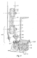
- This type of cylinder 7, 8, 9, with reference to the figure 4 as taught by the document EP 1364129 comprises a housing 10 forming a cylinder 11 in which a piston 12 slides, and having a longitudinal opening 13, such as a slot, over the entire length of the stroke of the piston 12 (either 4.5 meters or 9 meters) .
- the slot 13 of the housing 10, on either side of the piston 12 is closed by a lamelliform seal (not shown), which passes longitudinally through the piston 12, so that the latter can move back and forth in the cylinder 11 without the chambers (not visible in the figures) of the cylinder 7, 8, or 9 lose their hermeticity.
- the three cylinders 7, 8, 9 of the same guide 6 are in turn secured or engaged at the beginning of the race and during the drive of the carriage 4 which follows and then disengaged or disengaged at the end race, exercising successively and in series their driving action of the cover element 3, as will now be explained.
- the carriage 4 comprises two clutch devices 41, 42 symmetrical with respect to a median plane M, one 41 upstream side of the sliding A and the other 42 downstream side, and the mechanical connection 14 of the piston 12 of each cylinder 7, 8 comprises a clutch finger 22 arranged to cooperate with one of these two clutch devices 41, 42, regardless of the direction of sliding A or B.
- a transfer platform 16, or 17 respectively arranged to separate the drive carriage 4 from the upstream cylinder 7, respectively 8, and connect it to the downstream cylinder 8, respectively 9, in the direction of the indicated sliding A.
- a transfer platform 16 or 17 respectively arranged to separate the drive carriage 4 from the upstream cylinder 7, respectively 8, and connect it to the downstream cylinder 8, respectively 9, in the direction of the indicated sliding A.
- the sliding direction B it suffices to invert the references.
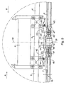
- the platform 16 comprises a cam track 18 with two ramps or inclined paths 19, 20 of slopes equal but opposite, rising upstream and downstream downstream, separated by a bearing 21.
- the profile of the cam path 18 as described above and shown on the figure 5 allows to guide the two clutch devices 41, 42 so that, at the end of travel of the upstream cylinder 7, the drive carriage 4 is in the clutch position on the two cylinders 7 and 8 and that the drive trolley 4 by the downstream cylinder can cause its disengagement of the upstream cylinder 7.
- each clutch device 41, 42 comprises a clutch rocker 43 pivotally mounted about an axis 44 on the carriage 4, the two axes 44 being eccentric with respect to a vertical plane M, transverse to the wagon and plane of symmetry for this carriage 4, and each latch 43 comprises two clutch hooks 45, 46 spaced apart from each other by a clearance 47 sufficient to allow placing the two fingers 22, upstream and downstream, simultaneously in position clutching the two latches 43 without mechanical interference.
- each latch 43 is not identical and have an inclined edge slopes chosen to slide on the slopes of the cam path 18 in both directions A and B taking into account the positions of the axes 44 of pivoting on the drive carriage 4.
- each hook 45, 46 of each clutch lever 43 of the carriage 4 externally has an inclined edge (not referenced) slidable on one or the other of the ramps 20 up or down the cam path 18 of the transfer platform 16.
- the clutch transfer platform 16 of the cover element 3 sliding on the guide 6, a driving jack 7 to a another 8, comprises a path 18 with two clutch-clutch functions 20 and 19 respectively exerting a clutch function and a disengagement function in the direction A or B of the driving of the element 3.
- the element to be slidably driven is a frame for mounting a tarpaulin cover of a rail freight platform, but as the drive system above can be iterated along a guide as much as times that the relative lengths of the jacks and the freight platforms require it, it can be a platform of road or maritime freight, or even of a silo, a hangar or a other activity area, for example sports or seasonal, such as a swimming pool.
Landscapes
- Engineering & Computer Science (AREA)
- Transportation (AREA)
- Mechanical Engineering (AREA)
- Mechanical Operated Clutches (AREA)
- Hydraulic Clutches, Magnetic Clutches, Fluid Clutches, And Fluid Joints (AREA)
- Forklifts And Lifting Vehicles (AREA)
- Portable Nailing Machines And Staplers (AREA)
- Actuator (AREA)
Claims (14)
- System (15) zum gleitenden Antrieb eines Elements (3, 4) auf einer Führung (6) mittels Betätigungsgliedern (7, 8, 9) mit einer Antriebslänge, die kleiner als die Länge der Führung (6) ist, wobei das System dadurch gekennzeichnet ist, dass es mindestens zwei Betätigungsglieder (7, 8) aufweist, die dafür vorgesehen sind, beim Gleiten fest mit dem Element (3, 4) verbunden zu sein, und so montiert sind, dass sie ihre Antriebswirkungen auf das Element (3, 4) in Reihe ausüben, und eine Übertragungs-Plattform (16, 17) aufweist, die zwischen den zwei Betätigungsgliedern (7, 8) angeordnet ist, die dafür vorgesehen ist, das Element (3, 4) von einem der Betätigungsglieder (7) zu lösen und es mit dem anderen (8) zu verbinden.
- System nach Anspruch 1, wobei das Element (3, 4), das angetrieben werden soll, zwei Kopplungsvorrichtungen (41, 42) aufweist, wobei jedes Betätigungsglied (7, 8) ein Kopplungsorgan (22) aufweist, das für das Zusammenwirken mit einer der Kopplungsvorrichtungen (41, 42) des Elements (3, 4) vorgesehen ist, wobei die Plattform (16) dafür vorgesehen ist, dass, in Endlage (30) eines der Betätigungsglieder (7), das Element (3, 4), das angetrieben werden soll, an die zwei Betätigungsglieder (7, 8) angekoppelt ist, wobei der Antrieb des Elements (3, 4) durch das andere der Betätigungsglieder (7, 8) die Abkopplung des Elements (3, 4) von dem Betätigungsglied (7) in Endlage (30) bewirkt.
- System nach Anspruch 2, wobei die Kopplung des Elements an dem anderen Betätigungsglied mit Spiel (47) realisiert wird.
- System nach einem der Ansprüche 2 und 3, wobei jede Kopplungsvorrichtung (41, 42) eine an dem Element (4) schwenkbar montierte (44) Kopplungswippe (43) aufweist, mit zwei Kopplungshaken (45, 46), die voneinander beabstandet (47) sind, jeweils für den Antrieb durch die zwei Betätigungsglieder (7, 8) in Reihe.
- System nach einem der Ansprüche 2 bis 4, wobei jede Kopplungsvorrichtung (41, 42) eine an dem Element (4) schwenkbar montierte (44) Kopplungswippe (43) aufweist, mit zwei Kopplungshaken (45, 46), die voneinander beabstandet (47) sind, jeweils für den Antrieb durch jedes der Betätigungsglieder (7, 8) in den beiden Richtungen (A, B).
- System nach einem der Ansprüche 4 und 5, wobei die zwei Kopplungswippen (43) identisch sind und in entgegengesetzter Richtung an dem Element (4) montiert sind.
- System nach einem der Ansprüche 1 bis 6, wobei die Übertragungs-Plattform (16) einen Nockenweg (18) aufweist, der dafür vorgesehen ist, mit den Kopplungsvorrichtungen (41, 42) des Elements (4) zusammenzuwirken und die eine (42) an dem einen (8) der Betätigungsglieder anzukoppeln, während sie gleichzeitig die andere (41) der Vorrichtungen von dem anderen (7) der Betätigungsglieder löst.
- System nach Anspruch 7, wobei der Nockenweg (18) der Übertragungs-Plattform (16) in den zwei Antriebsrichtungen (A, B) einen aufsteigenden Wegabschnitt (19) und einen absteigenden Wegabschnitt (20) aufweist, die durch einen Podestabschnitt (21) beabstandet sind.
- System nach einem der Ansprüche 5 bis 8, wobei jede Kopplungswippe (41, 42) des Elements (4) einen geneigten Rand aufweist, der dafür vorgesehen ist, mit einem der aufsteigenden (19) und absteigenden (20) Abschnitte des Nockenwegs (18) der Übertragungs-Plattform (16) zusammenzuwirken.
- System nach einem der Ansprüche 1 bis 9, wobei das Element (4), das zum Gleiten angetrieben werden soll, ein Rahmen für die Montage einer Planenabdeckung (2) eines Elements (3) der Anordnung ist, die eine Eisenbahnplattform, Straßenplattform oder Offshore-Plattform umfasst.
- System nach einem der Ansprüche 1 bis 9, wobei das Element (4), das zum Gleiten angetrieben werden soll, ein Rahmen für die Montage einer Planenabdeckung (2) der Anordnung ist, die ein Silo, einen Schuppen und ein Becken umfasst.
- System nach einem der Ansprüche 1 bis 11, wobei die Betätigungsglieder (7, 8) pneumatische Zylinder mit Kolben ohne Kolbenstange sind.
- System nach Anspruch 12, wobei das Kopplungsorgan der Zylinder (7, 8) ein Finger (22) ist, der an ihrem Kolben (12) montiert ist.
- Eisenbahnwaggon mit einer Frachtplattform (1) und einem Antriebssystem nach einem der Ansprüche 1 bis 9, mit drei Betätigungsgliedern (7, 8, 9) und zwei Plattformen (16, 17), die auf der Frachtplattform (1) in Reihe angeordnet sind.
Applications Claiming Priority (1)
| Application Number | Priority Date | Filing Date | Title |
|---|---|---|---|
| FR0601358A FR2897327B1 (fr) | 2006-02-16 | 2006-02-16 | Systeme d'entrainement d'un element en coulissement sur un guide et plate-forme de transfert d'embrayage d'un element a entrainer en coulissement sur un guide |
Publications (2)
| Publication Number | Publication Date |
|---|---|
| EP1820712A1 EP1820712A1 (de) | 2007-08-22 |
| EP1820712B1 true EP1820712B1 (de) | 2012-01-25 |
Family
ID=37192284
Family Applications (1)
| Application Number | Title | Priority Date | Filing Date |
|---|---|---|---|
| EP07290202A Ceased EP1820712B1 (de) | 2006-02-16 | 2007-02-16 | System zum Antrieb eines auf einer Führung gleitenden Elements und Plattform zur Kupplungsübertragung eines anzutreibenden, auf einer Führung gleitenden Elements |
Country Status (3)
| Country | Link |
|---|---|
| EP (1) | EP1820712B1 (de) |
| AT (1) | ATE542726T1 (de) |
| FR (1) | FR2897327B1 (de) |
Citations (2)
| Publication number | Priority date | Publication date | Assignee | Title |
|---|---|---|---|---|
| FR2038139A1 (de) * | 1969-04-02 | 1971-01-08 | Gewerk Eisenhuette Westfalia | |
| GB2330568A (en) * | 1997-10-22 | 1999-04-28 | Caterpillar Inc | Quick coupling device with over centre spring |
Family Cites Families (4)
| Publication number | Priority date | Publication date | Assignee | Title |
|---|---|---|---|---|
| GB2157246B (en) * | 1984-04-10 | 1987-11-25 | Structure Flex Limited | Retractable cover assembly for a load carrying vehicle |
| SE514857C2 (sv) * | 1997-06-02 | 2001-05-07 | Jonsson & Paulsson Ind Ab | Täckanordning för järnvägsvagn |
| EP1116635A1 (de) * | 2000-01-13 | 2001-07-18 | Grandwaggon Aktiebolag | Ein Endstück einer Abdeckanordnung für Güter-Transportmittel |
| DE10109482A1 (de) * | 2001-02-28 | 2002-09-12 | Festo Ag & Co | Kolbenstangenloser Linearantrieb |
-
2006
- 2006-02-16 FR FR0601358A patent/FR2897327B1/fr not_active Expired - Fee Related
-
2007
- 2007-02-16 AT AT07290202T patent/ATE542726T1/de active
- 2007-02-16 EP EP07290202A patent/EP1820712B1/de not_active Ceased
Patent Citations (2)
| Publication number | Priority date | Publication date | Assignee | Title |
|---|---|---|---|---|
| FR2038139A1 (de) * | 1969-04-02 | 1971-01-08 | Gewerk Eisenhuette Westfalia | |
| GB2330568A (en) * | 1997-10-22 | 1999-04-28 | Caterpillar Inc | Quick coupling device with over centre spring |
Also Published As
| Publication number | Publication date |
|---|---|
| ATE542726T1 (de) | 2012-02-15 |
| EP1820712A1 (de) | 2007-08-22 |
| FR2897327A1 (fr) | 2007-08-17 |
| FR2897327B1 (fr) | 2008-05-23 |
Similar Documents
| Publication | Publication Date | Title |
|---|---|---|
| ES2895736T3 (es) | Estructura de toldo | |
| EP1292476A1 (de) | Transport- und scrägverladesystem für waggons in einem bahnhof für den kombinierten schienen-/strassen- transport und zugehöriges verfahren | |
| FR2752554A1 (fr) | Rancher porteur a moyen de levage integre et ensemble porteur constitue d'au moins un couple de deux ranchers lies fonctionnellement entre eux | |
| CA2142694A1 (fr) | Ensemble d'accouplement entre deux structures wagon successives et un bogie commun | |
| EP2307237B1 (de) | Entlang einem teilabschnitt verschiebbarer unterlegteil, der durch schwenken gegen diesen teilabschnitt umgeklappt werden kann, für jeden reifen eines von einer transporteinheit beförderten strassenfahrzeugs | |
| FR2677314A1 (fr) | Wagon special permettant en fonctionnement autonome la recuperation ou la mise a disposition des bogies pour rail - route dans n'importe quelle gare. | |
| EP1820713B1 (de) | Faltbares Abdecksystem verschiebbar geführt auf ein Hydraulikzylinder | |
| FR2999217A1 (fr) | Installation de convoyage de vehicules automobiles a transmission d'efforts equilibree | |
| EP1820712B1 (de) | System zum Antrieb eines auf einer Führung gleitenden Elements und Plattform zur Kupplungsübertragung eines anzutreibenden, auf einer Führung gleitenden Elements | |
| EP2480449A1 (de) | System zur beladung/entladung eines fahrzeugs von einem trägerschiff aus und entsprechendes trägerschiff | |
| US4366607A (en) | Overcenter tensioning engagement and release device | |
| EP0112778B1 (de) | Tragrahmen zum Aufnehmen eines Wagens oder Güterbehälters für Verwendung auf Strasse, Schiene und Wasser | |
| EP0184510A2 (de) | Öffnungsvorrichtung für Entladeklappen | |
| CA3046506A1 (fr) | Procede de manoeuvre de portes de soute d'atterrisseur d'aeronef | |
| EP0358541B1 (de) | Hub- und Verriegelungsvorrichtung für eine Last oder einen Behälter auf einem Fahrzeug | |
| WO2020104908A2 (fr) | Conteneur équipé d'un système de verrouillage de conteneur | |
| EP1292477B1 (de) | Einheit für den kombinierten Schienen/Strassentransport mit einer Vorrichtung zur Fixierung des Abstandes zwischen den endseitigen Plattformen während des Be-und/oder Entladens | |
| EP0063521B1 (de) | Flachbodenwagen geeignet zum Transport von abnehmbaren Strassenfahrzeug-Aufbauten | |
| FR2769874A1 (fr) | Toit decouvrable pour receptacle de transport a chargement par le haut notamment pour benne ou semi-benne | |
| FR2924399A1 (fr) | Systeme de chargement et de dechargement de dechets pour remorque | |
| EP2064111A1 (de) | Vorrichtung zur modifizierung der hülle eines schwimmkörpers und amphibienfahrzeug mit einer solchen vorrichtung | |
| EP0391767A1 (de) | Zur Aufnahme mindestens eines Containers geeigneter Fahrzeuganhänger | |
| EP0856450A1 (de) | Anordnung zur Festlegung von Lasten auf einem Lastentransportfahrzeug | |
| FR2754776A1 (fr) | Vehicule de transport a bachage lateral | |
| FR2774054A1 (fr) | Wagon a plate-forme pivotante permettant d'effectuer rapidement l'embarquement, la fixation, le debarquement d'un camion |
Legal Events
| Date | Code | Title | Description |
|---|---|---|---|
| PUAI | Public reference made under article 153(3) epc to a published international application that has entered the european phase |
Free format text: ORIGINAL CODE: 0009012 |
|
| AK | Designated contracting states |
Kind code of ref document: A1 Designated state(s): AT BE BG CH CY CZ DE DK EE ES FI FR GB GR HU IE IS IT LI LT LU LV MC NL PL PT RO SE SI SK TR |
|
| AX | Request for extension of the european patent |
Extension state: AL BA HR MK YU |
|
| 17P | Request for examination filed |
Effective date: 20080214 |
|
| AKX | Designation fees paid |
Designated state(s): AT BE BG CH CY CZ DE DK EE ES FI FR GB GR HU IE IS IT LI LT LU LV MC NL PL PT RO SE SI SK TR |
|
| 17Q | First examination report despatched |
Effective date: 20091216 |
|
| GRAP | Despatch of communication of intention to grant a patent |
Free format text: ORIGINAL CODE: EPIDOSNIGR1 |
|
| GRAS | Grant fee paid |
Free format text: ORIGINAL CODE: EPIDOSNIGR3 |
|
| GRAA | (expected) grant |
Free format text: ORIGINAL CODE: 0009210 |
|
| AK | Designated contracting states |
Kind code of ref document: B1 Designated state(s): AT BE BG CH CY CZ DE DK EE ES FI FR GB GR HU IE IS IT LI LT LU LV MC NL PL PT RO SE SI SK TR |
|
| REG | Reference to a national code |
Ref country code: GB Ref legal event code: FG4D Free format text: NOT ENGLISH |
|
| REG | Reference to a national code |
Ref country code: DE Ref legal event code: R081 Ref document number: 602007020216 Country of ref document: DE Owner name: SNCF MOBILITES, FR Free format text: FORMER OWNER: SOCIETE NATIONALE DES CHEMINS DE FER FRANCAIS, PARIS, FR |
|
| REG | Reference to a national code |
Ref country code: CH Ref legal event code: EP |
|
| REG | Reference to a national code |
Ref country code: AT Ref legal event code: REF Ref document number: 542726 Country of ref document: AT Kind code of ref document: T Effective date: 20120215 |
|
| REG | Reference to a national code |
Ref country code: IE Ref legal event code: FG4D |
|
| REG | Reference to a national code |
Ref country code: DE Ref legal event code: R096 Ref document number: 602007020216 Country of ref document: DE Effective date: 20120322 |
|
| REG | Reference to a national code |
Ref country code: NL Ref legal event code: VDEP Effective date: 20120125 |
|
| LTIE | Lt: invalidation of european patent or patent extension |
Effective date: 20120125 |
|
| PG25 | Lapsed in a contracting state [announced via postgrant information from national office to epo] |
Ref country code: LT Free format text: LAPSE BECAUSE OF FAILURE TO SUBMIT A TRANSLATION OF THE DESCRIPTION OR TO PAY THE FEE WITHIN THE PRESCRIBED TIME-LIMIT Effective date: 20120125 Ref country code: BG Free format text: LAPSE BECAUSE OF FAILURE TO SUBMIT A TRANSLATION OF THE DESCRIPTION OR TO PAY THE FEE WITHIN THE PRESCRIBED TIME-LIMIT Effective date: 20120425 Ref country code: IS Free format text: LAPSE BECAUSE OF FAILURE TO SUBMIT A TRANSLATION OF THE DESCRIPTION OR TO PAY THE FEE WITHIN THE PRESCRIBED TIME-LIMIT Effective date: 20120525 Ref country code: NL Free format text: LAPSE BECAUSE OF FAILURE TO SUBMIT A TRANSLATION OF THE DESCRIPTION OR TO PAY THE FEE WITHIN THE PRESCRIBED TIME-LIMIT Effective date: 20120125 |
|
| REG | Reference to a national code |
Ref country code: IE Ref legal event code: FD4D |
|
| PG25 | Lapsed in a contracting state [announced via postgrant information from national office to epo] |
Ref country code: LV Free format text: LAPSE BECAUSE OF FAILURE TO SUBMIT A TRANSLATION OF THE DESCRIPTION OR TO PAY THE FEE WITHIN THE PRESCRIBED TIME-LIMIT Effective date: 20120125 Ref country code: FI Free format text: LAPSE BECAUSE OF FAILURE TO SUBMIT A TRANSLATION OF THE DESCRIPTION OR TO PAY THE FEE WITHIN THE PRESCRIBED TIME-LIMIT Effective date: 20120125 Ref country code: PL Free format text: LAPSE BECAUSE OF FAILURE TO SUBMIT A TRANSLATION OF THE DESCRIPTION OR TO PAY THE FEE WITHIN THE PRESCRIBED TIME-LIMIT Effective date: 20120125 Ref country code: PT Free format text: LAPSE BECAUSE OF FAILURE TO SUBMIT A TRANSLATION OF THE DESCRIPTION OR TO PAY THE FEE WITHIN THE PRESCRIBED TIME-LIMIT Effective date: 20120525 Ref country code: GR Free format text: LAPSE BECAUSE OF FAILURE TO SUBMIT A TRANSLATION OF THE DESCRIPTION OR TO PAY THE FEE WITHIN THE PRESCRIBED TIME-LIMIT Effective date: 20120426 |
|
| REG | Reference to a national code |
Ref country code: AT Ref legal event code: MK05 Ref document number: 542726 Country of ref document: AT Kind code of ref document: T Effective date: 20120125 |
|
| PG25 | Lapsed in a contracting state [announced via postgrant information from national office to epo] |
Ref country code: MC Free format text: LAPSE BECAUSE OF NON-PAYMENT OF DUE FEES Effective date: 20120229 Ref country code: CY Free format text: LAPSE BECAUSE OF FAILURE TO SUBMIT A TRANSLATION OF THE DESCRIPTION OR TO PAY THE FEE WITHIN THE PRESCRIBED TIME-LIMIT Effective date: 20120125 |
|
| PGFP | Annual fee paid to national office [announced via postgrant information from national office to epo] |
Ref country code: IT Payment date: 20120328 Year of fee payment: 6 |
|
| PG25 | Lapsed in a contracting state [announced via postgrant information from national office to epo] |
Ref country code: SE Free format text: LAPSE BECAUSE OF FAILURE TO SUBMIT A TRANSLATION OF THE DESCRIPTION OR TO PAY THE FEE WITHIN THE PRESCRIBED TIME-LIMIT Effective date: 20120125 Ref country code: EE Free format text: LAPSE BECAUSE OF FAILURE TO SUBMIT A TRANSLATION OF THE DESCRIPTION OR TO PAY THE FEE WITHIN THE PRESCRIBED TIME-LIMIT Effective date: 20120125 Ref country code: CZ Free format text: LAPSE BECAUSE OF FAILURE TO SUBMIT A TRANSLATION OF THE DESCRIPTION OR TO PAY THE FEE WITHIN THE PRESCRIBED TIME-LIMIT Effective date: 20120125 Ref country code: DK Free format text: LAPSE BECAUSE OF FAILURE TO SUBMIT A TRANSLATION OF THE DESCRIPTION OR TO PAY THE FEE WITHIN THE PRESCRIBED TIME-LIMIT Effective date: 20120125 Ref country code: RO Free format text: LAPSE BECAUSE OF FAILURE TO SUBMIT A TRANSLATION OF THE DESCRIPTION OR TO PAY THE FEE WITHIN THE PRESCRIBED TIME-LIMIT Effective date: 20120125 Ref country code: SI Free format text: LAPSE BECAUSE OF FAILURE TO SUBMIT A TRANSLATION OF THE DESCRIPTION OR TO PAY THE FEE WITHIN THE PRESCRIBED TIME-LIMIT Effective date: 20120125 Ref country code: IE Free format text: LAPSE BECAUSE OF FAILURE TO SUBMIT A TRANSLATION OF THE DESCRIPTION OR TO PAY THE FEE WITHIN THE PRESCRIBED TIME-LIMIT Effective date: 20120125 |
|
| PG25 | Lapsed in a contracting state [announced via postgrant information from national office to epo] |
Ref country code: SK Free format text: LAPSE BECAUSE OF FAILURE TO SUBMIT A TRANSLATION OF THE DESCRIPTION OR TO PAY THE FEE WITHIN THE PRESCRIBED TIME-LIMIT Effective date: 20120125 |
|
| PLBE | No opposition filed within time limit |
Free format text: ORIGINAL CODE: 0009261 |
|
| STAA | Information on the status of an ep patent application or granted ep patent |
Free format text: STATUS: NO OPPOSITION FILED WITHIN TIME LIMIT |
|
| GBPC | Gb: european patent ceased through non-payment of renewal fee |
Effective date: 20120425 |
|
| 26N | No opposition filed |
Effective date: 20121026 |
|
| PG25 | Lapsed in a contracting state [announced via postgrant information from national office to epo] |
Ref country code: GB Free format text: LAPSE BECAUSE OF NON-PAYMENT OF DUE FEES Effective date: 20120425 Ref country code: AT Free format text: LAPSE BECAUSE OF FAILURE TO SUBMIT A TRANSLATION OF THE DESCRIPTION OR TO PAY THE FEE WITHIN THE PRESCRIBED TIME-LIMIT Effective date: 20120125 |
|
| REG | Reference to a national code |
Ref country code: DE Ref legal event code: R097 Ref document number: 602007020216 Country of ref document: DE Effective date: 20121026 |
|
| PG25 | Lapsed in a contracting state [announced via postgrant information from national office to epo] |
Ref country code: ES Free format text: LAPSE BECAUSE OF FAILURE TO SUBMIT A TRANSLATION OF THE DESCRIPTION OR TO PAY THE FEE WITHIN THE PRESCRIBED TIME-LIMIT Effective date: 20120506 |
|
| PGFP | Annual fee paid to national office [announced via postgrant information from national office to epo] |
Ref country code: CH Payment date: 20130213 Year of fee payment: 7 |
|
| PGFP | Annual fee paid to national office [announced via postgrant information from national office to epo] |
Ref country code: BE Payment date: 20130301 Year of fee payment: 7 |
|
| PG25 | Lapsed in a contracting state [announced via postgrant information from national office to epo] |
Ref country code: TR Free format text: LAPSE BECAUSE OF FAILURE TO SUBMIT A TRANSLATION OF THE DESCRIPTION OR TO PAY THE FEE WITHIN THE PRESCRIBED TIME-LIMIT Effective date: 20120125 |
|
| PG25 | Lapsed in a contracting state [announced via postgrant information from national office to epo] |
Ref country code: LU Free format text: LAPSE BECAUSE OF NON-PAYMENT OF DUE FEES Effective date: 20120216 |
|
| PG25 | Lapsed in a contracting state [announced via postgrant information from national office to epo] |
Ref country code: HU Free format text: LAPSE BECAUSE OF FAILURE TO SUBMIT A TRANSLATION OF THE DESCRIPTION OR TO PAY THE FEE WITHIN THE PRESCRIBED TIME-LIMIT Effective date: 20070216 |
|
| BERE | Be: lapsed |
Owner name: SOC. NATIONALE DES CHEMINS DE FER FRANCAIS Effective date: 20140228 |
|
| REG | Reference to a national code |
Ref country code: CH Ref legal event code: PL |
|
| PG25 | Lapsed in a contracting state [announced via postgrant information from national office to epo] |
Ref country code: CH Free format text: LAPSE BECAUSE OF NON-PAYMENT OF DUE FEES Effective date: 20140228 Ref country code: LI Free format text: LAPSE BECAUSE OF NON-PAYMENT OF DUE FEES Effective date: 20140228 |
|
| PG25 | Lapsed in a contracting state [announced via postgrant information from national office to epo] |
Ref country code: BE Free format text: LAPSE BECAUSE OF NON-PAYMENT OF DUE FEES Effective date: 20140228 |
|
| REG | Reference to a national code |
Ref country code: FR Ref legal event code: PLFP Year of fee payment: 9 |
|
| REG | Reference to a national code |
Ref country code: FR Ref legal event code: CA Effective date: 20150428 Ref country code: FR Ref legal event code: CD Owner name: SNCF MOBILITES, FR Effective date: 20150428 |
|
| REG | Reference to a national code |
Ref country code: DE Ref legal event code: R081 Ref document number: 602007020216 Country of ref document: DE Owner name: SNCF MOBILITES, FR Free format text: FORMER OWNER: SOCIETE NATIONALE DES CHEMINS DE FER FRANCAIS, PARIS, FR |
|
| REG | Reference to a national code |
Ref country code: FR Ref legal event code: PLFP Year of fee payment: 10 |
|
| PG25 | Lapsed in a contracting state [announced via postgrant information from national office to epo] |
Ref country code: IT Free format text: LAPSE BECAUSE OF NON-PAYMENT OF DUE FEES Effective date: 20140216 |
|
| REG | Reference to a national code |
Ref country code: FR Ref legal event code: PLFP Year of fee payment: 11 |
|
| REG | Reference to a national code |
Ref country code: FR Ref legal event code: PLFP Year of fee payment: 12 |
|
| REG | Reference to a national code |
Ref country code: DE Ref legal event code: R081 Ref document number: 602007020216 Country of ref document: DE Owner name: SNCF VOYAGEURS, FR Free format text: FORMER OWNER: SNCF MOBILITES, SAINT-DENIS, FR |
|
| PGFP | Annual fee paid to national office [announced via postgrant information from national office to epo] |
Ref country code: DE Payment date: 20240213 Year of fee payment: 18 |
|
| PGFP | Annual fee paid to national office [announced via postgrant information from national office to epo] |
Ref country code: FR Payment date: 20240228 Year of fee payment: 18 |
|
| REG | Reference to a national code |
Ref country code: DE Ref legal event code: R119 Ref document number: 602007020216 Country of ref document: DE |
|
| PG25 | Lapsed in a contracting state [announced via postgrant information from national office to epo] |
Ref country code: DE Free format text: LAPSE BECAUSE OF NON-PAYMENT OF DUE FEES Effective date: 20250902 |
|
| PG25 | Lapsed in a contracting state [announced via postgrant information from national office to epo] |
Ref country code: FR Free format text: LAPSE BECAUSE OF NON-PAYMENT OF DUE FEES Effective date: 20250228 |