EP1820720A1 - Verfahren zur installation einer führungsschiene für ein kraftfahrzeug, vorrichtung zur installation einer führungsschiene für ein kraftfahrzeug und vorrichtung zur installation eines weichen glieds - Google Patents
Verfahren zur installation einer führungsschiene für ein kraftfahrzeug, vorrichtung zur installation einer führungsschiene für ein kraftfahrzeug und vorrichtung zur installation eines weichen glieds Download PDFInfo
- Publication number
- EP1820720A1 EP1820720A1 EP05809678A EP05809678A EP1820720A1 EP 1820720 A1 EP1820720 A1 EP 1820720A1 EP 05809678 A EP05809678 A EP 05809678A EP 05809678 A EP05809678 A EP 05809678A EP 1820720 A1 EP1820720 A1 EP 1820720A1
- Authority
- EP
- European Patent Office
- Prior art keywords
- run channel
- sash
- section
- roller
- pressing
- Prior art date
- Legal status (The legal status is an assumption and is not a legal conclusion. Google has not performed a legal analysis and makes no representation as to the accuracy of the status listed.)
- Granted
Links
Images



Classifications
-
- B—PERFORMING OPERATIONS; TRANSPORTING
- B25—HAND TOOLS; PORTABLE POWER-DRIVEN TOOLS; MANIPULATORS
- B25J—MANIPULATORS; CHAMBERS PROVIDED WITH MANIPULATION DEVICES
- B25J5/00—Manipulators mounted on wheels or on carriages
- B25J5/02—Manipulators mounted on wheels or on carriages travelling along a guideway
-
- B—PERFORMING OPERATIONS; TRANSPORTING
- B23—MACHINE TOOLS; METAL-WORKING NOT OTHERWISE PROVIDED FOR
- B23P—METAL-WORKING NOT OTHERWISE PROVIDED FOR; COMBINED OPERATIONS; UNIVERSAL MACHINE TOOLS
- B23P19/00—Machines for simply fitting together or separating metal parts or objects, or metal and non-metal parts, whether or not involving some deformation; Tools or devices therefor so far as not provided for in other classes
- B23P19/04—Machines for simply fitting together or separating metal parts or objects, or metal and non-metal parts, whether or not involving some deformation; Tools or devices therefor so far as not provided for in other classes for assembling or disassembling parts
- B23P19/047—Machines for simply fitting together or separating metal parts or objects, or metal and non-metal parts, whether or not involving some deformation; Tools or devices therefor so far as not provided for in other classes for assembling or disassembling parts for flexible profiles, e.g. sealing or decorating strips in grooves or on other profiles by devices moving along the flexible profile
-
- B—PERFORMING OPERATIONS; TRANSPORTING
- B25—HAND TOOLS; PORTABLE POWER-DRIVEN TOOLS; MANIPULATORS
- B25J—MANIPULATORS; CHAMBERS PROVIDED WITH MANIPULATION DEVICES
- B25J9/00—Program-controlled manipulators
- B25J9/0084—Program-controlled manipulators comprising a plurality of manipulators
-
- B—PERFORMING OPERATIONS; TRANSPORTING
- B25—HAND TOOLS; PORTABLE POWER-DRIVEN TOOLS; MANIPULATORS
- B25J—MANIPULATORS; CHAMBERS PROVIDED WITH MANIPULATION DEVICES
- B25J9/00—Program-controlled manipulators
- B25J9/0084—Program-controlled manipulators comprising a plurality of manipulators
- B25J9/0087—Dual arms
-
- B—PERFORMING OPERATIONS; TRANSPORTING
- B60—VEHICLES IN GENERAL
- B60J—WINDOWS, WINDSCREENS, NON-FIXED ROOFS, DOORS, OR SIMILAR DEVICES FOR VEHICLES; REMOVABLE EXTERNAL PROTECTIVE COVERINGS SPECIALLY ADAPTED FOR VEHICLES
- B60J10/00—Sealing arrangements
- B60J10/45—Assembling sealing arrangements with vehicle parts
-
- Y—GENERAL TAGGING OF NEW TECHNOLOGICAL DEVELOPMENTS; GENERAL TAGGING OF CROSS-SECTIONAL TECHNOLOGIES SPANNING OVER SEVERAL SECTIONS OF THE IPC; TECHNICAL SUBJECTS COVERED BY FORMER USPC CROSS-REFERENCE ART COLLECTIONS [XRACs] AND DIGESTS
- Y10—TECHNICAL SUBJECTS COVERED BY FORMER USPC
- Y10T—TECHNICAL SUBJECTS COVERED BY FORMER US CLASSIFICATION
- Y10T29/00—Metal working
- Y10T29/49—Method of mechanical manufacture
- Y10T29/49826—Assembling or joining
-
- Y—GENERAL TAGGING OF NEW TECHNOLOGICAL DEVELOPMENTS; GENERAL TAGGING OF CROSS-SECTIONAL TECHNOLOGIES SPANNING OVER SEVERAL SECTIONS OF THE IPC; TECHNICAL SUBJECTS COVERED BY FORMER USPC CROSS-REFERENCE ART COLLECTIONS [XRACs] AND DIGESTS
- Y10—TECHNICAL SUBJECTS COVERED BY FORMER USPC
- Y10T—TECHNICAL SUBJECTS COVERED BY FORMER US CLASSIFICATION
- Y10T29/00—Metal working
- Y10T29/49—Method of mechanical manufacture
- Y10T29/49826—Assembling or joining
- Y10T29/49863—Assembling or joining with prestressing of part
- Y10T29/4987—Elastic joining of parts
-
- Y—GENERAL TAGGING OF NEW TECHNOLOGICAL DEVELOPMENTS; GENERAL TAGGING OF CROSS-SECTIONAL TECHNOLOGIES SPANNING OVER SEVERAL SECTIONS OF THE IPC; TECHNICAL SUBJECTS COVERED BY FORMER USPC CROSS-REFERENCE ART COLLECTIONS [XRACs] AND DIGESTS
- Y10—TECHNICAL SUBJECTS COVERED BY FORMER USPC
- Y10T—TECHNICAL SUBJECTS COVERED BY FORMER US CLASSIFICATION
- Y10T29/00—Metal working
- Y10T29/49—Method of mechanical manufacture
- Y10T29/49826—Assembling or joining
- Y10T29/49863—Assembling or joining with prestressing of part
- Y10T29/4987—Elastic joining of parts
- Y10T29/49872—Confining elastic part in socket
-
- Y—GENERAL TAGGING OF NEW TECHNOLOGICAL DEVELOPMENTS; GENERAL TAGGING OF CROSS-SECTIONAL TECHNOLOGIES SPANNING OVER SEVERAL SECTIONS OF THE IPC; TECHNICAL SUBJECTS COVERED BY FORMER USPC CROSS-REFERENCE ART COLLECTIONS [XRACs] AND DIGESTS
- Y10—TECHNICAL SUBJECTS COVERED BY FORMER USPC
- Y10T—TECHNICAL SUBJECTS COVERED BY FORMER US CLASSIFICATION
- Y10T29/00—Metal working
- Y10T29/49—Method of mechanical manufacture
- Y10T29/49826—Assembling or joining
- Y10T29/49945—Assembling or joining by driven force fit
-
- Y—GENERAL TAGGING OF NEW TECHNOLOGICAL DEVELOPMENTS; GENERAL TAGGING OF CROSS-SECTIONAL TECHNOLOGIES SPANNING OVER SEVERAL SECTIONS OF THE IPC; TECHNICAL SUBJECTS COVERED BY FORMER USPC CROSS-REFERENCE ART COLLECTIONS [XRACs] AND DIGESTS
- Y10—TECHNICAL SUBJECTS COVERED BY FORMER USPC
- Y10T—TECHNICAL SUBJECTS COVERED BY FORMER US CLASSIFICATION
- Y10T29/00—Metal working
- Y10T29/49—Method of mechanical manufacture
- Y10T29/49998—Work holding
-
- Y—GENERAL TAGGING OF NEW TECHNOLOGICAL DEVELOPMENTS; GENERAL TAGGING OF CROSS-SECTIONAL TECHNOLOGIES SPANNING OVER SEVERAL SECTIONS OF THE IPC; TECHNICAL SUBJECTS COVERED BY FORMER USPC CROSS-REFERENCE ART COLLECTIONS [XRACs] AND DIGESTS
- Y10—TECHNICAL SUBJECTS COVERED BY FORMER USPC
- Y10T—TECHNICAL SUBJECTS COVERED BY FORMER US CLASSIFICATION
- Y10T29/00—Metal working
- Y10T29/53—Means to assemble or disassemble
-
- Y—GENERAL TAGGING OF NEW TECHNOLOGICAL DEVELOPMENTS; GENERAL TAGGING OF CROSS-SECTIONAL TECHNOLOGIES SPANNING OVER SEVERAL SECTIONS OF THE IPC; TECHNICAL SUBJECTS COVERED BY FORMER USPC CROSS-REFERENCE ART COLLECTIONS [XRACs] AND DIGESTS
- Y10—TECHNICAL SUBJECTS COVERED BY FORMER USPC
- Y10T—TECHNICAL SUBJECTS COVERED BY FORMER US CLASSIFICATION
- Y10T29/00—Metal working
- Y10T29/53—Means to assemble or disassemble
- Y10T29/53657—Means to assemble or disassemble to apply or remove a resilient article [e.g., tube, sleeve, etc.]
Definitions
- the present invention relates to an automobile run channel installing method for installing a run channel for an automobile on a sash of an automobile door, a device for installing a run channel for an automobile, and a soft member installation device for installing a soft member such as a run channel for an automobile door shaped substantially concave in section in a concave groove of a substantially concave member in section such as a sash of an automobile door.
- Patent Literature 1 Japanese Patent Application Publication No. 2002-205551
- Patent Literature 1 has a problem in that it does not contribute to man-hour reduction since a worker uses a seal rubber fitting jig to install a run channel for an automobile door in a concave groove of a sash of an automobile door.
- the present invention has been made in view of such a problem that methods of the prior art have and an object thereof is to provide a versatile method for installing a run channel for an automobile door which is capable of man-hour reduction and applicable to multiple models, a device for installing a run channel for an automobile, and a soft member installation device.
- an automobile run channel installing method for installing a run channel on a sash of an automobile door, comprising the steps of setting a run channel to a conveyance means having a pair of arms, inserting both end sections of the run channel set to the pair of arms from a gap formed by an inner panel and an outer panel in a downward directed state into an automobile door and positioning the run channel along a sash, pushing both corner sections of the run channel set to the pair of arms into a corner section of an upper sash, pressing and fitting an upper-sash roller attached in at least one of the arms into a concave section of the run channel to move from the corner section of the upper sash so as to fit the run channel into the upper sash, and pressing and fitting the lower-sash roller attached to the arm and inserted into the automobile door from the gap into a concave section of the run channel to move from a higher portion to a. lower portion of the lower sash and to fit the
- an automobile run channel installation device for installing a run channel on a sash of an automobile door, comprising a conveyance means having a pair of arms which operate in a coordinated manner and a run channel installation jig provided on each of the arms, wherein the run channel installation jig has a first holding means for holding both corner sections of the run channel, a pressing means for pressing and fitting the both corner sections of the run channel held by the first holding means into a corner section of an upper sash, a rotatable upper-sash roller for pressing and fitting the run channel into the upper sash, a second holding means for holding both end sections of the run channel, a rotatable lower-sash roller for pressing and fitting the run channel into the lower sash, and a slide means for arbitrarily setting distance of the second holding means and the lower-sash roller relative to the first holding means.
- a soft member installation device for installing a soft member having a groove being long and presenting a substantially concave shape in section in a concave groove of a member to be installed being long and presenting a substantially concave shape in section, comprising a supporting member made of an elastic member of a thin plate shape in section, a roller rotatably installed in a shaft member provided perpendicularly to a tip surface of the supporting member and capable of being freely inserted into the groove of the soft member, and a control means for controlling a posture of the supporting member freely to enable the soft member to be installed in the concave groove of the member to be installed with operations of the roller.
- a run channel for an automobile door being a long soft object can be installed accurately and automatically in a sash of an automobile door.
- improvement and stabilization in quality of installation of a run channel for an automobile door can be attained.
- a soft member such as a run channel for an automobile door being a long soft object can be installed accurately and automatically in a concave groove present in a substantially concave member in section such as a sash of an automobile door without causing control means to bear a large burden.
- improvement and stabilization in quality of installation of a soft member such as a run channel for an automobile door in a concave groove can be attained.
- Figure 1 is a schematic explanatory diagram of a run channel installation device for an automobile
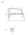
- Figures 2 illustrate perspective view (a) of an automobile door and a sectional view (b) of a run channel for an automobile door
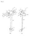
- Figures 3 are schematic diagrams of a run channel installation jig
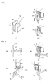
- Figures 4 are schematic diagrams of a first holding means and pressing means
- Figures 5 are schematic diagrams of an upper-sash roller
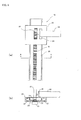
- Figures 6 are schematic diagrams of a slide means
- Figures 7 are schematic diagrams of second holding means and a lower-sash roller
- Figures 8 are diagrams for describing operations of a lower-sash roller and a slide rail.
- a device for installing a run channel for an automobile door related to the present invention comprises, as illustrated in Figure 1, a first robot arm 1 and a second robot arm 2 being a pair of robot arms with multiple joints which operate in a coordinated manner and run channel installation jigs 3 respectively provided in the tips of those first robot arm 1 and second robot arm 2.
- the first robot arm 1 and the second robot arm 2 are respectively composed of arm sections 1a and 2a with three axes (three degree of freedom) and wrist sections 1b and 2b with three axes (three degree of freedom) provided at the tips of the arm sections 1a and 2a and are both installed in a base 5 with a gate-form frame 4 being a running shaft S. Run channel installation jigs 3 are attached to the wrist sections 1b and 2b.
- the base 5 has a pivot L between the running shaft S and the robot arms 1 and 2.
- the present device has 14 axes (14 degrees of freedom) in total.
- the operation for installing a run channel for an automobile door with the first robot arm 1 and the second robot arm 2 is taught and played back with a control device (not illustrated in the drawing).
- an automobile door (right side front door) 6 is configured by an inner panel 6a, an outer panel 6b and an automobile door sash 8 as a substantially concave member in section where an automobile door run channel (herein after to be referred to as "rum channel") 7 is installed.
- a concave section 7a is formed in the run channel 7 as illustrated in Figure 2(b).
- the inner panel 6a and the outer panel 6b form a gap 6c.
- An automobile door sash 8 has a front corner section 8a and a rear corner section 8b and includes: an upper section 8c from the front corner section 8a to the rear corner section 8b; an upper front section 8d approximately perpendicular to the front corner section 8a; an upper rear section 8e approximately perpendicular to the rear corner section 8b; a lower front section 8f in succession to the upper front section 8d and covered by the inner panel 6a and the outer panel 6b; and a lower rear section 8g in succession to the upper rear section 8e and covered by the inner panel 6a and the outer panel 6b, respectively having a concave groove 9.
- the upper section 8c, the upper front section 8d and the upper rear section 8e are called upper sashes.
- the lower front section 8f and the lower rear section 8g are called lower sashes.
- a run channel installation jig 3 has a first holding means 10 for holding both corner sections 7b and 7c of the run channel 7, a pressing means 11 for pressing and fitting both corner sections 7b and 7c of the run channel 7 held by the first holding means 10 into corner sections 8a. and 8b of an upper sash, a rotatable upper-sash roller 12 pressing and fitting the run channel 7 into the upper sash, a second holding means 13 for holding both end sections 7d and 7e of the run channel 7, a rotatable lower-sash roller 14 for pressing and fitting the run channel 7 into a lower sash, and a slide means 15 for arbitrarily setting the distance of the second holding means 13 and the lower-sash roller 14 relative to the first holding means 10.
- Figures 3 illustrate a run channel installation jig 3 installed in the tip of the second robot arm 2.
- the first holding means 10 has, as illustrated in Figure 4(a), a nail member 20 with thickness enabling insertion into the concave section 7a of the run channel 7 and an opening and closing member 22 formed capable of freely opening and closing with a hinge 21 provided in the nail member 20 and a spring (not illustrated in the drawing) for sandwiching the run channel 7 with the spring power together with the nail member 20 inserted into the concave section 7a.
- the nail member 20 is fixed to a guide member 24 through an installation bracket 20a.
- the guide member 24 is installed on installation surfaces of the wrist sections 1b and 2b through a force sensor 23.
- a tapered section 22a is formed for enabling the nail member 20 to press the run channel 7 at the occasion of holding the run channel 7, and thereby the run channel 7 to widen the gap formed by the nail member 20 and the opening and closing member 22 to be allowed to enter the spacing between them.
- that tapered section 22a plays a role of supporting the corner section of the sash 8 to press the opening and closing member 22 so that the first holding means 10 smoothly comes into an open state also at the occasion of inserting the both corner sections 7b and 7c of the run channel 7 held by the first holding means 10 into the sash 8.
- the nail member 20 is preferably covered by the concave section 7a of the run channel 7. Then, the run channel 7 fits to the nail member 20 in the concave section 7a thereof and is held by the nail member 20 and the opening and closing member 22 with the spring force.
- the nail member 20 is preferably removed from the run channel 7 after pushing the both corner sections 7b and 7c of the run channel 7 into the corner sections 8a and 8b of the sash 8 with the nail member 20.
- the pressing means 11 completes its function in the case where the nail member 20 is inserted into the concave section 7a of the run channel 7 and thereby pressed and fitted into the corner sections 8a and 8b of the upper sash.
- the upper-sash roller 12 is rotatably installed in a shaft member 26 provided in the guide member 24 through the bracket 25.
- the shaft member 26 is provided approximately in the center of the installation surface of the wrist sections 1b and 2b and approximately perpendicular to the installation surface.
- a periphery section 12a of the upper-sash roller 12 is formed to provide thickness for allowing insertion into the concave section 7a of the run channel 7.
- the upper-sash roller 12 can ensure installation of the run channel 7 in the automobile door sash 8 by pushing and inserting the periphery section 12a into the concave section 7a of the run channel 7 and sliding and rotating the periphery section 12a to move.
- an operation with a single degree of freedom of only pushing and fitting with the upper-sash roller 12 enables installation of the run channel 7 in the automobile door sash 8.
- a slide means 15 has a guide member 24; a slide rail 30 made of an elastic member in a thin plate shape and substantially U-shaped in section to slidably fit into the guide member 24; a rack 31 laid across the slide rail 30; a pinion 32 meshing with the rack 31; a servomotor 33 with the pinion 32 fixed to a rotary shaft; and a control section (not illustrated in the drawing) having a position detector, motor drive circuit and the like for driving the servomotor 33 to control a protruding amount of the slide rail 30.
- the servomotor 33 is provided in a fixed manner in the guide member 24 through the bracket 34.
- the slide means 15 is provided with a pad 35 for pressing the surface of the slide rail 30, where the rack 31 is laid, on the opposite side in order to restrain shrinkage of the slide rail 30 due to a load in the case where the servomotor 33 is in a halt state; and a cylinder 36 providing the pad 35 with a desired pressing force.
- the cylinder 36 is provided in a fixed manner in the guide member 24 thorough the bracket (not illustrated in the drawing).
- a bearing 37 smoothes protruding operation of the slide rail 30.
- the second holding means 13 has a plate member 38 provided in the vicinity of the tip of the slide rail 30; an opening and closing member 39 for sandwiching the both end sections 7d and 7e of the run channel 7 together with the plate member 38; and a cylinder 40 providing the opening and closing member 39 with a holding force.
- a shaft pin 39a rotates the opening and closing member 39. The forward and backward movement of the cylinder 40 enables the opening and closing member 39 to open and close.
- the run channel 7 is omitted from illustration in Figure 7(a).
- the lower-sash roller 14 is installed rotatably in a shaft member 41 provided perpendicularly to the tip surface of the slide rail 30 made of an elastic member.
- the shaft member 41 is arranged approximately in parallel to the shaft member 26 of the upper-sash roller 12.
- a. periphery section 14a of the lower-sash roller 14 is formed to provide thickness for allowing insertion into the concave section 7a.
- the slide rail 30 is, as illustrated in Figure 8(a), inclined by predetermined angles ⁇ and ⁇ with respect to the perpendicular direction.
- the lower-sash roller 14 installed in the tip of the slide rail 30 inclined by the predetermined angles ⁇ and ⁇ takes the state of pushing the concave groove 9 of the upper end of the lower front section 8f and the lower rear section 8g through the run channel 7 as a teaching point TP and teaches the periphery section 14a of the lower-sash roller 14 to move from that teaching point TP on a line TL from a higher portion to a lower portion along each of the shapes of the lower front section 8f and the lower rear section 8g.
- Figure 8(b) depicts the lower rear section 8g and the run channel 7 is not illustrated in the drawing.
- the lower-sash roller 14 installed in the tip of the slide rail 30 made of an elastic member maintains, as illustrated in Figures 8(d) and (e), the state of fitting into the concave groove 9 of the lower front section 8f and the lower rear section 8g forming a curved shape slightly curved in the right and left directions through the run channel 7, carries out complicated operations and moves along a curve PL with deflection of the slide rail 30 and a reaction force from the lower front section 8f and the lower rear section 8g at the occasion of a play back. Then, the run channel 7 is smoothly fitted into the concave groove 9 in a substantially concave shape in section of the lower front section 8f and the lower rear section 8g.
- the moving operation on the line TL along the shape of the lower front section 8f and the lower rear section 8g is preferably taught to the lower-sash roller 14 and there is no necessity for teaching of moving operations along the *curved shape of the lower front section 8f and the lower rear section 8g. Therefore, it is possible to simplify teaching operations of the first robot arm 1 and the second robot arm 2.
- a soft member installation device related to the present invention is configured by a lower-sash roller 14; a slide rail 30 for supporting the lower-sash roller 14; a first robot arm 1 and a second robot arm 2 for controlling the posture of the slide rail 30 freely so that the operation of the lower-sash roller 14 enables installation of the run channel 7 in the concave groove 9 of the lower front section 8f and the lower rear section 8g of the sash 8.
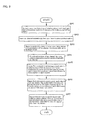
- step SP1 an operator makes the first holding means 10 and the second holding means 13 respectively installed in the first robot arm 1 and the second robot arm 2 that are ready in the original positions and are taught a program for the run channel installing operations in advance hold the both corner sections 7b and 7c and the both end sections 7d and 7e of the run channel 7 where a loosen is coated.
- a slide rail 30 is extended to a maximum extent.
- length of the run channel 7 from the nail member 20 of the first robot arm 1 to the nail member 20 of the second robot arm 2 is approximately equal to the length of the upper section 8c from the front corner section 8a to the rear corner section 8b in the automobile door sash 8.
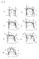
- step SP2 when a startup switch is pressed, the first robot arm 1 and the second robot arm 2 start playing back the program of the run channel installing operation. Then, as illustrated in Figure 10(b), the first robot arm 1 and the second robot arm 2 are driven.
- the lower-sash roller 14 and the second holding means 13 of the run channel installing jig 3 installed in the first robot arm 1 are inserted from a gap (approximately 25 mm in width) 6c formed by the inner panel 6a and the outer panel 6b opening in the vicinity of the root (for example, 10 cm from the root) of the automobile door sash 8 (upper front section 8d).
- the lower-sash roller 14 and the second holding means 13 of the run channel installing jig 3 installed in the second robot arm 2 are also inserted from a gap (approximately 25 mm in width) 6c formed by the inner panel 6a and the outer panel 6b opening in the vicinity of the root (for example, 10 cm from the root) of the automobile door sash 8 (upper rear section 8e).
- the lower-sash roller 14 and the second holding means 13 provided in the tip of the slide rail 30 extended to the maximum extent are inserted to reach a predetermined position without interrupting the inner panel 6a, the outer panel 6b and the like.
- step SP3 the second holding means 13 is opened to release the both end sections 7d and 7e of the run channel 7. Moreover, as illustrated in Figure 10(c), in order to release the lower-sash roller 14 from the gap 6c formed by the inner panel 6a and the outer panel 6b, the slide rail 30 is shortened to the maximum extent.
- step SP4 the first robot arm 1 and the second robot arm 2 are driven.
- the corner section 7b of the run channel 7 where the nail member 20 of the first robot arm 1 is inserted is fit into the front corner section 8a of the sash 8.
- the corner section 7c of the run channel 7 where the nail member 20 of the second robot arm 2 is inserted is fit into the rear corner section 8b of the sash 8.
- step SP5 in order to sequentially fit the run channel 7 from the upper front section 8d in the vicinity of the front corner section 8a, the first robot arm 1 causes the upper-sash roller 12 which pressed and fit the periphery section 12a into the concave section 7a in the vicinity of the front corner section 8a to slide and rotate to move to the lower end of the upper front section 8d.
- the second robot arm 2 causes the upper-sash roller 12 which pressed and fit the periphery section 12a into the concave section 7a in the vicinity of the rear corner section 8b to slide and rotate to move to the position being three quarters in the upper section 8c closer to the front corner section 8a.
- step SP6 in order to push the run channel 7 into the portion of the remaining around one quarter of the upper section 8c, the first robot arm 1 causes the upper-sash roller 12 which pressed and fit the periphery section 12a. into the concave section 7a in the vicinity of the front corner section 8a to slide and rotate to move in a reciprocated manner in the distance of approximately two-thirds in the upper section 8c from the front corner section 8a toward the rear corner section 8b.
- the second robot arm 2 causes the upper-sash roller 12 which pressed and fit the periphery section 12a into the concave section 7a in the vicinity of the rear corner section 8b to slide and rotate to move to the lower end of the upper rear section 8e.
- step SP7 as illustrated in Figure 10(g), the slide rail 30 is extended to reach a predetermined length.
- the first robot arm 1 causes the lower-sash roller 14 which pressed and fit the periphery section 14a into the concave section 7a in the vicinity of the upper front section 8d to slide and rotate to move to the lower end of the lower front section 8f.
- the slide rail 30 with the lower-sash roller 14 installed in the tip presses the lower-sash roller 14 to the run channel 7 at a predetermined angle ⁇ to the perpendicular direction.
- the lower-sash roller 14 is caused to play back the teaching trace TL from the teaching point TP in the state where the lower-sash roller 14 is pressed to the run channel 7.
- the lower-sash roller 14 maintains the state of fitting into the concave groove 9 of the lower front section 8f through the run channel 7, carries out complicated operations and moves along a curve PL with deflection of the slide rail 30 and a reaction force from the lower front section 8f.
- the run channel 7 is smoothly fitted into the concave groove 9 in a substantially concave shape of the lower front section 8f
- the second robot arm 2 when the slide rail 30 is extended to reach a predetermined length, in order to sequentially push the run channel 7 from the upper section of the lower rear section 8g in the vicinity of the upper rear section 8e, the second robot arm 2 causes the lower-sash roller 14 which pressed and insert the periphery section 14a into the concave section 7a in the vicinity of the upper rear section 8e to move in a complicated manner to the lower end of the lower rear section 8g.
- the slide rail 30 with the lower-sash roller 14 installed in the tip presses the lower-sash roller 14 to the run channel 7 at a predetermined angle ⁇ to the perpendicular direction, which is intended to obtain similar operations and advantages to those in the case of the first robot arm 1.
- the first robot arm 1 and the second robot arm 2 respectively remove the lower-sash roller 14 from the gap 6c formed by the inner panel 6a and the outer panel 6b and come back to the original positions so as to finish the installation operation for installing the run channel 7 in the automobile door sash 8.
- the present invention contributes to man-hour reduction of operations for installing a run channel for automobile door being a long soft object on a sash of an automobile door.
- improvement and stabilization in quality of installation of a run channel for an automobile door can be achieved.
Landscapes
- Engineering & Computer Science (AREA)
- Mechanical Engineering (AREA)
- Robotics (AREA)
- Automobile Manufacture Line, Endless Track Vehicle, Trailer (AREA)
- Operating, Guiding And Securing Of Roll- Type Closing Members (AREA)
- Tents Or Canopies (AREA)
Priority Applications (1)
| Application Number | Priority Date | Filing Date | Title |
|---|---|---|---|
| EP08154842A EP1942047B1 (de) | 2004-11-22 | 2005-11-22 | Vorrichtung zur Installation eines weichen Elements |
Applications Claiming Priority (3)
| Application Number | Priority Date | Filing Date | Title |
|---|---|---|---|
| JP2004337655A JP4322783B2 (ja) | 2004-11-22 | 2004-11-22 | 自動車用ランチャンネル取付方法及びその装置 |
| JP2004337677A JP4386825B2 (ja) | 2004-11-22 | 2004-11-22 | 軟体部材取付装置 |
| PCT/JP2005/021404 WO2006054764A1 (ja) | 2004-11-22 | 2005-11-22 | 自動車用ランチャンネル取付方法及びその装置と、軟体部材取付装置 |
Related Child Applications (1)
| Application Number | Title | Priority Date | Filing Date |
|---|---|---|---|
| EP08154842A Division EP1942047B1 (de) | 2004-11-22 | 2005-11-22 | Vorrichtung zur Installation eines weichen Elements |
Publications (3)
| Publication Number | Publication Date |
|---|---|
| EP1820720A1 true EP1820720A1 (de) | 2007-08-22 |
| EP1820720A4 EP1820720A4 (de) | 2007-11-21 |
| EP1820720B1 EP1820720B1 (de) | 2009-01-14 |
Family
ID=36407295
Family Applications (2)
| Application Number | Title | Priority Date | Filing Date |
|---|---|---|---|
| EP05809678A Expired - Lifetime EP1820720B1 (de) | 2004-11-22 | 2005-11-22 | Verfahren zur installation einer führungsschiene für ein kraftfahrzeug und vorrichtung zur installation einer führungsschiene für ein kraftfahrzeug |
| EP08154842A Expired - Lifetime EP1942047B1 (de) | 2004-11-22 | 2005-11-22 | Vorrichtung zur Installation eines weichen Elements |
Family Applications After (1)
| Application Number | Title | Priority Date | Filing Date |
|---|---|---|---|
| EP08154842A Expired - Lifetime EP1942047B1 (de) | 2004-11-22 | 2005-11-22 | Vorrichtung zur Installation eines weichen Elements |
Country Status (5)
| Country | Link |
|---|---|
| US (1) | US8033004B2 (de) |
| EP (2) | EP1820720B1 (de) |
| CA (1) | CA2588563A1 (de) |
| DE (2) | DE602005012428D1 (de) |
| WO (1) | WO2006054764A1 (de) |
Cited By (4)
| Publication number | Priority date | Publication date | Assignee | Title |
|---|---|---|---|---|
| EP1820719A4 (de) * | 2004-11-30 | 2008-04-16 | Honda Motor Co Ltd | Verfahren und vorrichtung zur formteilinstallation |
| FR3042773A1 (fr) * | 2015-10-27 | 2017-04-28 | Renault Sas | Dispositif de mise en place d’une coulisse sur une porte de vehicule |
| EP3520954A1 (de) * | 2018-01-31 | 2019-08-07 | Dr. Ing. h.c. F. Porsche AG | Montagesystem zum montieren eines dichtungsprofils an einem karosserieflansch |
| WO2020229272A1 (de) * | 2019-05-16 | 2020-11-19 | Thyssenkrupp System Engineering Gmbh | Applikationseinheit mit andrückkraftmessung |
Families Citing this family (2)
| Publication number | Priority date | Publication date | Assignee | Title |
|---|---|---|---|---|
| CN101844301B (zh) * | 2010-06-13 | 2011-10-19 | 浙江金刚汽车有限公司 | 一种玻璃压装机 |
| US11110554B2 (en) | 2019-07-19 | 2021-09-07 | Honda Motor Co., Ltd. | Garnish installing apparatus and methods of making and using the same |
Family Cites Families (12)
| Publication number | Priority date | Publication date | Assignee | Title |
|---|---|---|---|---|
| US4760636A (en) | 1986-07-18 | 1988-08-02 | General Motors Corporation | Apparatus of a robot for installing weather stripping in a door or like opening |
| US4715110A (en) | 1986-07-18 | 1987-12-29 | General Motors Corporation | Apparatus of a robot for installing weather stripping in a door or like opening |
| US5179774A (en) * | 1990-05-24 | 1993-01-19 | Ford Motor Company | Apparatus and method for mechanically applying a sealing strip |
| DE69132040T2 (de) | 1990-09-21 | 2000-11-02 | Merck & Co., Inc. | Wachstumsfaktor II für vaskuläre Endothelzellen |
| JPH05200638A (ja) * | 1992-01-22 | 1993-08-10 | Mazda Motor Corp | 小物部品の組付方法および装置 |
| JPH08155843A (ja) | 1994-11-30 | 1996-06-18 | Nishikawa Rubber Co Ltd | ウエザーストリップの取付治具 |
| JPH08174353A (ja) | 1994-12-26 | 1996-07-09 | Mitsubishi Motors Corp | ウェザーストリップ装着装置 |
| US5875670A (en) | 1996-07-31 | 1999-03-02 | The Standard Products Company | Tool for roll crimping a flange cover |
| JP2000211374A (ja) * | 1999-01-26 | 2000-08-02 | Nishikawa Rubber Co Ltd | グラスランの取付方法およびグラスラン取付用治具 |
| CA2362832C (en) * | 2000-04-04 | 2008-05-27 | Honda Giken Kogyo Kabushiki Kaisha | Tool and process for press-fitting weather strip |
| JP2002205551A (ja) | 2001-01-10 | 2002-07-23 | Honda Motor Co Ltd | 車両ドアのサッシ枠用シールラバー嵌合方法及びその嵌合治具 |
| US7552283B2 (en) * | 2006-01-20 | 2009-06-23 | Qualcomm Incorporated | Efficient memory hierarchy management |
-
2005
- 2005-11-22 DE DE602005012428T patent/DE602005012428D1/de not_active Expired - Lifetime
- 2005-11-22 CA CA002588563A patent/CA2588563A1/en not_active Abandoned
- 2005-11-22 EP EP05809678A patent/EP1820720B1/de not_active Expired - Lifetime
- 2005-11-22 EP EP08154842A patent/EP1942047B1/de not_active Expired - Lifetime
- 2005-11-22 DE DE602005017832T patent/DE602005017832D1/de not_active Expired - Lifetime
- 2005-11-22 WO PCT/JP2005/021404 patent/WO2006054764A1/ja not_active Ceased
- 2005-11-22 US US11/719,815 patent/US8033004B2/en not_active Expired - Fee Related
Cited By (4)
| Publication number | Priority date | Publication date | Assignee | Title |
|---|---|---|---|---|
| EP1820719A4 (de) * | 2004-11-30 | 2008-04-16 | Honda Motor Co Ltd | Verfahren und vorrichtung zur formteilinstallation |
| FR3042773A1 (fr) * | 2015-10-27 | 2017-04-28 | Renault Sas | Dispositif de mise en place d’une coulisse sur une porte de vehicule |
| EP3520954A1 (de) * | 2018-01-31 | 2019-08-07 | Dr. Ing. h.c. F. Porsche AG | Montagesystem zum montieren eines dichtungsprofils an einem karosserieflansch |
| WO2020229272A1 (de) * | 2019-05-16 | 2020-11-19 | Thyssenkrupp System Engineering Gmbh | Applikationseinheit mit andrückkraftmessung |
Also Published As
| Publication number | Publication date |
|---|---|
| EP1942047B1 (de) | 2009-11-18 |
| DE602005017832D1 (de) | 2009-12-31 |
| US8033004B2 (en) | 2011-10-11 |
| EP1942047A3 (de) | 2008-07-30 |
| CA2588563A1 (en) | 2006-05-26 |
| EP1820720A4 (de) | 2007-11-21 |
| EP1820720B1 (de) | 2009-01-14 |
| EP1942047A2 (de) | 2008-07-09 |
| US20090139070A1 (en) | 2009-06-04 |
| WO2006054764A1 (ja) | 2006-05-26 |
| DE602005012428D1 (de) | 2009-03-05 |
Similar Documents
| Publication | Publication Date | Title |
|---|---|---|
| EP1820720B1 (de) | Verfahren zur installation einer führungsschiene für ein kraftfahrzeug und vorrichtung zur installation einer führungsschiene für ein kraftfahrzeug | |
| JP3459345B2 (ja) | テープ貼付装置 | |
| EP1115589B1 (de) | Werkzeug und verfahren zum anbringen von dichtungsprofilen | |
| US8146228B2 (en) | Automobile run channel fitting method and device | |
| EP1873102A2 (de) | Klebebandverbindungsvorrichtung | |
| JP2006306618A (ja) | 粘着テープ貼付け装置 | |
| JP4425116B2 (ja) | 自動車ドア用ランチャンネル把持装置 | |
| JP3634648B2 (ja) | 枠体用調整装置及び枠体の取付工法 | |
| JP4322783B2 (ja) | 自動車用ランチャンネル取付方法及びその装置 | |
| JP4386825B2 (ja) | 軟体部材取付装置 | |
| JPH10291167A (ja) | 可撓性を有する成形用の工具及び方法 | |
| JP4386764B2 (ja) | 軟体長手部材取付方法及びその装置 | |
| JP2008012952A (ja) | 車両用ウエザーストリップ取付装置 | |
| JP2008072928A (ja) | 結束機 | |
| JP3742640B2 (ja) | ドア枠装置 | |
| US20250250999A1 (en) | Space saving mechanism for installation of swing door operator | |
| JP2002205551A (ja) | 車両ドアのサッシ枠用シールラバー嵌合方法及びその嵌合治具 | |
| JP3755083B2 (ja) | 蝶番 | |
| JPS6220338Y2 (de) | ||
| KR20040060130A (ko) | 윈도우 개구부의 헤밍링크 및 헤밍방법 | |
| JP2017148898A (ja) | 押付治具 | |
| JP2006007967A (ja) | 粘着テープ貼付け方法およびその装置 | |
| JP4619182B2 (ja) | カーテンレールの段差解消方法 | |
| JP2000289966A (ja) | クリップガイド取付治具 | |
| CN113250571A (zh) | 门窗 |
Legal Events
| Date | Code | Title | Description |
|---|---|---|---|
| PUAI | Public reference made under article 153(3) epc to a published international application that has entered the european phase |
Free format text: ORIGINAL CODE: 0009012 |
|
| 17P | Request for examination filed |
Effective date: 20070522 |
|
| AK | Designated contracting states |
Kind code of ref document: A1 Designated state(s): DE GB |
|
| A4 | Supplementary search report drawn up and despatched |
Effective date: 20071022 |
|
| 17Q | First examination report despatched |
Effective date: 20071218 |
|
| DAX | Request for extension of the european patent (deleted) | ||
| RBV | Designated contracting states (corrected) |
Designated state(s): DE GB |
|
| GRAP | Despatch of communication of intention to grant a patent |
Free format text: ORIGINAL CODE: EPIDOSNIGR1 |
|
| RTI1 | Title (correction) |
Free format text: METHOD FOR INSTALLING RUN CHANNEL FOR AUTOMOBILE AND DEVICE FOR INSTALLING RUN CHANNEL FOR AUTOMOBILE |
|
| GRAS | Grant fee paid |
Free format text: ORIGINAL CODE: EPIDOSNIGR3 |
|
| GRAA | (expected) grant |
Free format text: ORIGINAL CODE: 0009210 |
|
| AK | Designated contracting states |
Kind code of ref document: B1 Designated state(s): DE GB |
|
| REG | Reference to a national code |
Ref country code: GB Ref legal event code: FG4D |
|
| REF | Corresponds to: |
Ref document number: 602005012428 Country of ref document: DE Date of ref document: 20090305 Kind code of ref document: P |
|
| PLBE | No opposition filed within time limit |
Free format text: ORIGINAL CODE: 0009261 |
|
| STAA | Information on the status of an ep patent application or granted ep patent |
Free format text: STATUS: NO OPPOSITION FILED WITHIN TIME LIMIT |
|
| 26N | No opposition filed |
Effective date: 20091015 |
|
| PGFP | Annual fee paid to national office [announced via postgrant information from national office to epo] |
Ref country code: DE Payment date: 20121114 Year of fee payment: 8 |
|
| PGFP | Annual fee paid to national office [announced via postgrant information from national office to epo] |
Ref country code: GB Payment date: 20121121 Year of fee payment: 8 |
|
| GBPC | Gb: european patent ceased through non-payment of renewal fee |
Effective date: 20131122 |
|
| REG | Reference to a national code |
Ref country code: DE Ref legal event code: R119 Ref document number: 602005012428 Country of ref document: DE Effective date: 20140603 |
|
| PG25 | Lapsed in a contracting state [announced via postgrant information from national office to epo] |
Ref country code: DE Free format text: LAPSE BECAUSE OF NON-PAYMENT OF DUE FEES Effective date: 20140603 |
|
| PG25 | Lapsed in a contracting state [announced via postgrant information from national office to epo] |
Ref country code: GB Free format text: LAPSE BECAUSE OF NON-PAYMENT OF DUE FEES Effective date: 20131122 |