EP1820965A1 - Méthode et dispositif pour régler la production énergétique dans une centrale thermique solaire - Google Patents
Méthode et dispositif pour régler la production énergétique dans une centrale thermique solaire Download PDFInfo
- Publication number
- EP1820965A1 EP1820965A1 EP06003298A EP06003298A EP1820965A1 EP 1820965 A1 EP1820965 A1 EP 1820965A1 EP 06003298 A EP06003298 A EP 06003298A EP 06003298 A EP06003298 A EP 06003298A EP 1820965 A1 EP1820965 A1 EP 1820965A1
- Authority
- EP
- European Patent Office
- Prior art keywords
- power plant
- solar
- plant part
- energy
- transfer medium
- Prior art date
- Legal status (The legal status is an assumption and is not a legal conclusion. Google has not performed a legal analysis and makes no representation as to the accuracy of the status listed.)
- Withdrawn
Links
Images


Classifications
-
- F—MECHANICAL ENGINEERING; LIGHTING; HEATING; WEAPONS; BLASTING
- F02—COMBUSTION ENGINES; HOT-GAS OR COMBUSTION-PRODUCT ENGINE PLANTS
- F02C—GAS-TURBINE PLANTS; AIR INTAKES FOR JET-PROPULSION PLANTS; CONTROLLING FUEL SUPPLY IN AIR-BREATHING JET-PROPULSION PLANTS
- F02C1/00—Gas-turbine plants characterised by the use of hot gases or unheated pressurised gases, as the working fluid
- F02C1/04—Gas-turbine plants characterised by the use of hot gases or unheated pressurised gases, as the working fluid the working fluid being heated indirectly
- F02C1/05—Gas-turbine plants characterised by the use of hot gases or unheated pressurised gases, as the working fluid the working fluid being heated indirectly characterised by the type or source of heat, e.g. using nuclear or solar energy
-
- F—MECHANICAL ENGINEERING; LIGHTING; HEATING; WEAPONS; BLASTING
- F03—MACHINES OR ENGINES FOR LIQUIDS; WIND, SPRING, OR WEIGHT MOTORS; PRODUCING MECHANICAL POWER OR A REACTIVE PROPULSIVE THRUST, NOT OTHERWISE PROVIDED FOR
- F03G—SPRING, WEIGHT, INERTIA OR LIKE MOTORS; MECHANICAL-POWER PRODUCING DEVICES OR MECHANISMS, NOT OTHERWISE PROVIDED FOR OR USING ENERGY SOURCES NOT OTHERWISE PROVIDED FOR
- F03G6/00—Devices for producing mechanical power from solar energy
- F03G6/06—Devices for producing mechanical power from solar energy with solar energy concentrating means
- F03G6/065—Devices for producing mechanical power from solar energy with solar energy concentrating means having a Rankine cycle
- F03G6/067—Binary cycle plants where the fluid from the solar collector heats the working fluid via a heat exchanger
-
- F—MECHANICAL ENGINEERING; LIGHTING; HEATING; WEAPONS; BLASTING
- F03—MACHINES OR ENGINES FOR LIQUIDS; WIND, SPRING, OR WEIGHT MOTORS; PRODUCING MECHANICAL POWER OR A REACTIVE PROPULSIVE THRUST, NOT OTHERWISE PROVIDED FOR
- F03G—SPRING, WEIGHT, INERTIA OR LIKE MOTORS; MECHANICAL-POWER PRODUCING DEVICES OR MECHANISMS, NOT OTHERWISE PROVIDED FOR OR USING ENERGY SOURCES NOT OTHERWISE PROVIDED FOR
- F03G6/00—Devices for producing mechanical power from solar energy
- F03G6/071—Devices for producing mechanical power from solar energy with energy storage devices
-
- F—MECHANICAL ENGINEERING; LIGHTING; HEATING; WEAPONS; BLASTING
- F03—MACHINES OR ENGINES FOR LIQUIDS; WIND, SPRING, OR WEIGHT MOTORS; PRODUCING MECHANICAL POWER OR A REACTIVE PROPULSIVE THRUST, NOT OTHERWISE PROVIDED FOR
- F03G—SPRING, WEIGHT, INERTIA OR LIKE MOTORS; MECHANICAL-POWER PRODUCING DEVICES OR MECHANISMS, NOT OTHERWISE PROVIDED FOR OR USING ENERGY SOURCES NOT OTHERWISE PROVIDED FOR
- F03G6/00—Devices for producing mechanical power from solar energy
- F03G6/098—Components, parts or details
- F03G6/108—Components, parts or details of the heat transfer system
- F03G6/111—Heat transfer fluids
- F03G6/114—Molten salts
-
- Y—GENERAL TAGGING OF NEW TECHNOLOGICAL DEVELOPMENTS; GENERAL TAGGING OF CROSS-SECTIONAL TECHNOLOGIES SPANNING OVER SEVERAL SECTIONS OF THE IPC; TECHNICAL SUBJECTS COVERED BY FORMER USPC CROSS-REFERENCE ART COLLECTIONS [XRACs] AND DIGESTS
- Y02—TECHNOLOGIES OR APPLICATIONS FOR MITIGATION OR ADAPTATION AGAINST CLIMATE CHANGE
- Y02E—REDUCTION OF GREENHOUSE GAS [GHG] EMISSIONS, RELATED TO ENERGY GENERATION, TRANSMISSION OR DISTRIBUTION
- Y02E10/00—Energy generation through renewable energy sources
- Y02E10/40—Solar thermal energy, e.g. solar towers
- Y02E10/46—Conversion of thermal power into mechanical power, e.g. Rankine, Stirling or solar thermal engines
Definitions
- the invention relates to a method for controlling the solar energy yield in a solar thermal power plant, which comprises at least a first solar power plant part with a solar field and a second power plant part, wherein the solar field generates solar energy with a solar energy yield.
- the energy between the solar field and the second power plant part is transported through a heat transfer medium.
- the second power plant part is designed for a maximum permissible solar energy supply.
- the invention relates to a device for controlling the solar energy yield in a solar thermal power plant, which comprises at least a first solar power plant part with a solar field and a second power plant part, wherein the first solar power plant part and the second power plant part are thermally coupled to each other.
- a solar thermal power plant uses solar radiant energy to produce electrical energy. It consists of a solar power plant part for absorbing solar energy and a second mostly conventional power plant part.
- the solar power plant part comprises a solar field circuit with a solar field, that is to say a concentration system which comprises geometrically different collectors.
- the concentrating collectors are the main component of the solar power plant part. More familiar collectors are the Paraboloidrinnenkollektor, the Fresnel collector, the solar tower and the parabolic mirror.
- the collectors concentrate the sun's rays onto an absorber tube placed in the focal line. There, the solar energy is absorbed and passed as heat to a heat transfer medium. Depending on the type of heat transfer medium, it is pumped directly to the conventional power plant part after heating. Thermal oil, water, air or molten salt can be used as the heat transfer medium.
- the conventional power plant part usually comprises a water-steam cycle with a steam and / or gas turbine and a generator and a capacitor.
- a steam turbine the heat input is replaced by the boiler by the heat input generated by the solar field.
- heat exchangers are interposed between the first solar power plant section, the associated solar field circuit and the conventional power plant section with the associated water-steam circuit in order to transfer the energy generated in the solar field from the heat transfer medium of the solar field circuit to the water tank. To transfer steam cycle.
- the electrical power of the solar thermal power plant is therefore determined on the one hand by the thermal properties of the heat transfer medium on the other hand to a large extent by the choice of power range of the turbine.
- a maximum thermal heat input into the water-steam cycle is necessary. If a higher solar energy input is produced in the solar field than is provided for the supply to the conventional power plant part, the solar irradiation is reduced. This is usually done by at least some solar panels of the solar field are rotated from the sun. However, this represents an energy loss.
- a conventional additional firing installed in the solar field cycle or a heat storage (storage), for example, a molten salt storage, a steam storage or a solid storage to the heat exchanger be installed the solar field cycle.
- a heat storage for example, a molten salt storage, a steam storage or a solid storage to the heat exchanger be installed the solar field cycle.
- an additional heat exchanger for the memory is required, which is designed for a meaningful mass flow range of the heat transfer medium.
- memory currently in the Research and testing. But in almost all cases, even greater development steps are necessary in order to be able to use them efficiently in a solar thermal power plant. A largely different solution to these problems would therefore be desirable.
- the object of the invention related to the method is therefore the indication of a method for controlling a solar thermal power plant, which is characterized even with interruption of solar radiation by, for example, cloud passage and thus lower solar radiation by a largely constant, maximum power generation by solar energy and a largely complete uptake of Solar energy allows.
- a further object is the disclosure of a device for controlling a solar thermal power plant, which in particular allows an implementation of the above-mentioned method.
- the object is achieved by a method for controlling a solar energy yield in a solar thermal power plant comprising at least a first solar power plant part with a solar field and a second power plant part, wherein the solar field generates solar energy with a solar energy yield, the energy between the solar field and the second power plant part is transported by a heat transfer medium, wherein the second power plant part is designed for a maximum allowable power, wherein an energy in the first solar power plant part on the maximum allowable power supply of the second power plant part is referred to as an excess energy and wherein at excess energy at least a partial flow the heat transfer medium is guided past the second power plant part.
- the invention is based on the recognition that the mass flow of the heat transfer medium in the solar field is influenced by the maximum and minimum permissible mass flow in the absorber tubes (avoidance of hot spots in the case of cloud passage).
- the heat transfer medium in the first solar power plant part is therefore due to the so-adjusting temperature, as well as the maximum allowable temperature of the heat transfer medium determined by yourself.
- the self-adjusting temperature of the heat transfer medium directly influences the energy generated in the second part of the power plant. In order to achieve a largely constant energy production by solar energy, it has been recognized in the invention that the maximum permissible temperature of the heat transfer medium is to be maintained over a wide range of operation.
- the bypassed partial flow is adjusted depending on the excess energy in the first solar power plant part.
- the partial flow is adjusted so that it corresponds exactly to the differential energy, that is, the excess energy minus the allowable for the second power plant part energy. This means that the second power plant part, which is supplied with substantially maximum permissible energy, and thus a substantially maximum, based on solar energy, power generation takes place.
- the partial stream passed by is fed to the mass flow of the heat transfer medium flowing back to the solar field.
- This mixture with the appropriate mixing temperature, is introduced into the solar field.
- the average temperature of the solar field inventory and thus the heat content is increased, ie solar energy is temporarily stored in the heat transfer medium (Short term memory).
- a short-term collapse of the solar energy input eg in cloud passage
- a drop in the power generation in the second power plant part is effectively counteracted.
- a premature unscrewing of solar panels from the sun is avoided here. So it is therefore possible an improved solar energy absorption.
- the differential energy that is to say the excess energy minus the energy permissible for the second power plant part, is used as a partial flow.
- This differential energy is then mixed again with the mass flow of the heat transfer medium, which flows back to the solar field and increases the energy of the heat transfer medium by this energy difference.
- a heat exchange is performed between the first solar power plant part and the second power plant part.
- another heat transfer medium can be used than in the second power plant part. Due to the heat exchange, the energy of the first solar power plant part is transmitted to the second power plant part. This transmission can take place, for example, by convection.
- At least one partial flow of the heat transfer medium is preferably conducted past the heat exchange. This avoids that the energy in the partial flow is transmitted from the heat transfer medium to the second power plant part.
- the solar energy generated by the solar field is at least partially buffered.
- a heat storage in the first solar power plant part and / or installed in the second power plant part for storage If the heat storage is operated with a different heat transfer medium than, for example, the solar field circuit / water-steam cycle, an additional heat exchanger for the memory is required, which is designed for a meaningful mass flow range.
- the method with a heat exchange and a storage preferably has the following steps:
- the first step is the generation of solar energy with a solar energy yield in the first part of the solar power plant.
- the solar energy is supplied to the second power plant part or for heat exchange. Through the supply to the heat exchange, the energy is then supplied to the second power plant part.
- the total or partial storage of the solar energy takes place at excess energy.
- At least one partial stream of the solar energy is preferably conducted past the second power plant part by means of the heat transfer medium.
- the mass flow of the heat transfer medium with the maximum allowable energy is supplied to the second power plant part. This can also be done via a heat exchange. As a result, then the power generation from solar energy in the second part of the power plant. When excess energy is first at least partially directed to the memory and transferred the heat in the memory. If the latter can no longer absorb the excess energy due to complete filling or other adjustment to the system, the partial flow of the heat transfer medium is conducted past the accumulator and the second power plant part with further excess energy and later to the already cooled mass flow of the heat transfer medium, which is in the solar field flows back in again.
- the average temperature of the solar field flowing back stream of heat transfer medium and thus the heat content is increased, ie solar energy is temporarily stored in the heat transfer medium (short-term storage). This can be a short-term Incursion of the solar energy input (eg in cloud passage) are compensated.
- one or more additional firing is performed in the first solar power plant part or / and in the second power plant part. This compensates for fluctuations in solar radiation and extends the operating time in the morning and evening hours. This is particularly advantageous when there are fixed power purchase contracts.
- the object is achieved by a device for controlling the solar energy yield in a solar thermal power plant comprising at least a first solar power plant part with a solar field and a second power plant part, wherein the first solar power plant part and the second power plant part are thermally coupled to each other, wherein to avoid the supply of energy to the second power plant part via a maximum energy yield one or more bypass lines for passing at least a portion of the energy generated in the solar power plant part are provided on the second power plant part.
- the device is particularly suitable for carrying out the method described above.
- the advantages of the method therefore also arise for the device.
- FIG. 1 shows a schematic structure of a solar thermal power plant 1 according to the prior art.
- This consists of a solar part 8 with a solar panel 2 in which the radiation is concentrated and heat energy is converted.
- the solar panel 2 for example, consist of Parabollrinnenkollektoren, solar towers, Paraboloidapt- or Fresnel mirror collectors. These concentrate the solar radiation onto an absorber tube (not shown) running in the focal line. In this, the concentrated solar radiation is converted into heat and delivered to a circulating heat transfer medium 3 in a conductor 4.
- the heat transfer medium 3 may be water vapor, thermal oil, air, molten salt.
- the solar thermal power plant 1 shown here consists of two circuits: a solar field circuit 5 and a conventional power plant cycle, which is designed here as a water-steam cycle 6.
- the solar field circuit 5 further consists of a storage facility 7 of the solar energy generated, for example, a molten salt storage, steam storage or solid storage and an additional firing 14, for example, from petroleum, natural gas to ensure a more uniform and extended heat input.
- the solar thermal power plant 1 consists of a conventional power plant part 9 with the water-steam cycle 6 for generating electrical energy. Between the solar field circuit 5 and the Water-steam cycle 6 heat exchangers 10 are interposed to transfer the energy from the solar field heat transfer medium to the water in the water-steam cycle 6.
- the conventional power plant part 9 consists of a steam and / or gas turbine 11, a generator 12 and a condenser 13.
- water is evaporated and overheated.
- turbine which drives the generator 12
- it is relaxed and then liquefied by a condenser and returned to the water-steam cycle 6.
- the water-steam circuit 6 may have an additional firing 14.
- FIG 2 and FIG 3 show the inventive method (FIG 2) and the inventive device (FIG 3) for controlling a solar thermal power plant 1 with heat exchanger 10 without memory.
- the generation of solar energy in the solar field 2 is determined by the prevailing solar radiation in connection with the minimum and maximum permissible mass flow in the absorber tube (not shown). If the mass flow is greater than the minimum permissible mass flow in the absorber tube (FIG. 2: S1), this is delivered by absorber to the heat transfer medium 3. If the mass flow generated by the solar field 2 in the conductors 4 is smaller than the maximum permissible energy supply of the conventional power plant part 9 and smaller than the maximum permissible temperature of the heat transfer medium 3 (FIG.
- the mass flow is preferably completely through the conventional power plant part 9 the heat exchanger 10 is supplied ( Figure 2: S3).
- the mass flow generated by the solar field 2 in the conductors 4 is greater than the maximum permissible energy supply of the conventional power plant part 9, but smaller than the maximum permissible temperature of the heat transfer medium 3 (FIG. 2: S4), then at least part of the energy produced by the solar field 2 becomes generated mass flow of the heat transfer medium 3 to the conventional power plant part 9 and here passed to the heat exchanger 10 ( Figure 2: S5).
- the heat exchanger 10 is preceded by one or more bypass lines 20 for passing a portion of the mass flow, that is, a portion of the solar energy.
- the differential mass flow between the current mass flow and the mass flow which corresponds to the maximum permissible energy supply of the conventional power plant part 9 is preferably conducted past the heat exchangers 10 through the bypass lines 20.
- the mass flow past the heat exchangers 10 is then mixed again at a mixing point 22 with the mass flow from the bypass lines 20.
- This mixture with the appropriate mixing temperature, is introduced into the solar field 2.
- the mixing temperature is now higher than the maximum allowable power supply of the conventional power plant part 9 corresponds.
- the average temperature of the solar field inventory and thus the heat content is increased, ie solar energy is temporarily stored in the heat transfer medium 3 in the conductors 4.
- a short-term collapse of the solar energy input eg in cloud passage
- the solar energy generated by the solar field 2 in the heat transfer medium 3 reaches a higher temperature than the permissible maximum temperature of the heat transfer medium 3, the solar radiation used is reduced, ie parts of the solar collectors are turned out of the sun (FIG. 2, S6).
- the method described here and the device can in principle also be applied to comparable power plant concepts such as solar thermal power plants 1 with / without storage 7 in the solar and / or conventional power plant part 9 and with / without additional firing 14 in the solar and / or conventional power plant part 9.
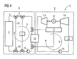
- FIG 4 for example, a Device for controlling a solar thermal power plant with memory shown.
Landscapes
- Engineering & Computer Science (AREA)
- Chemical & Material Sciences (AREA)
- Combustion & Propulsion (AREA)
- Life Sciences & Earth Sciences (AREA)
- Sustainable Development (AREA)
- Sustainable Energy (AREA)
- Mechanical Engineering (AREA)
- General Engineering & Computer Science (AREA)
- Physics & Mathematics (AREA)
- Thermal Sciences (AREA)
- High Energy & Nuclear Physics (AREA)
- Engine Equipment That Uses Special Cycles (AREA)
- Photovoltaic Devices (AREA)
Priority Applications (4)
| Application Number | Priority Date | Filing Date | Title |
|---|---|---|---|
| EP06003298A EP1820965A1 (fr) | 2006-02-17 | 2006-02-17 | Méthode et dispositif pour régler la production énergétique dans une centrale thermique solaire |
| EP07703777A EP1984623A1 (fr) | 2006-02-17 | 2007-01-11 | Procédé et dispositif pour réguler une production d'énergie solaire dans une centrale héliothermique |
| PCT/EP2007/050231 WO2007093464A1 (fr) | 2006-02-17 | 2007-01-11 | Procédé et dispositif pour réguler une production d'énergie solaire dans une centrale héliothermique |
| CNA2007800056749A CN101384819A (zh) | 2006-02-17 | 2007-01-11 | 调整太阳能热电站内太阳能产量的方法和设备 |
Applications Claiming Priority (1)
| Application Number | Priority Date | Filing Date | Title |
|---|---|---|---|
| EP06003298A EP1820965A1 (fr) | 2006-02-17 | 2006-02-17 | Méthode et dispositif pour régler la production énergétique dans une centrale thermique solaire |
Publications (1)
| Publication Number | Publication Date |
|---|---|
| EP1820965A1 true EP1820965A1 (fr) | 2007-08-22 |
Family
ID=36658761
Family Applications (2)
| Application Number | Title | Priority Date | Filing Date |
|---|---|---|---|
| EP06003298A Withdrawn EP1820965A1 (fr) | 2006-02-17 | 2006-02-17 | Méthode et dispositif pour régler la production énergétique dans une centrale thermique solaire |
| EP07703777A Withdrawn EP1984623A1 (fr) | 2006-02-17 | 2007-01-11 | Procédé et dispositif pour réguler une production d'énergie solaire dans une centrale héliothermique |
Family Applications After (1)
| Application Number | Title | Priority Date | Filing Date |
|---|---|---|---|
| EP07703777A Withdrawn EP1984623A1 (fr) | 2006-02-17 | 2007-01-11 | Procédé et dispositif pour réguler une production d'énergie solaire dans une centrale héliothermique |
Country Status (3)
| Country | Link |
|---|---|
| EP (2) | EP1820965A1 (fr) |
| CN (1) | CN101384819A (fr) |
| WO (1) | WO2007093464A1 (fr) |
Cited By (9)
| Publication number | Priority date | Publication date | Assignee | Title |
|---|---|---|---|---|
| FR2927959A1 (fr) * | 2008-02-27 | 2009-08-28 | Sophia Antipolis En Dev Soc Pa | Installation de generation d'energie electrique a partir d'energie solaire. |
| FR2965341A1 (fr) * | 2010-09-27 | 2012-03-30 | Areva Solar Inc | Fluide pour systeme de stockage de milieu pour vapeur d'eau a haute temperature |
| EP2546521A1 (fr) * | 2011-07-15 | 2013-01-16 | Siemens Aktiengesellschaft | Préchauffage surérogatoire à basse pression pour le réglage en fréquence ou secondaire et/ou primaire, d'une centrale thermo-solaire |
| WO2013069111A1 (fr) * | 2011-11-09 | 2013-05-16 | 株式会社日立製作所 | Dispositif de production d'électricité à turbine à gaz et procédé de fonctionnement de celui-ci |
| DE102012204218A1 (de) * | 2012-03-16 | 2013-09-19 | Siemens Aktiengesellschaft | Leistungsregelung und/oder Frequenzregelung bei einem solarthermischen Dampfkraftwerk |
| DE102012204219A1 (de) * | 2012-03-16 | 2013-09-19 | Siemens Aktiengesellschaft | Leistungsregelung und/oder Frequenzregelung bei einem solarthermischen Dampfkraftwerk |
| WO2014128327A1 (fr) * | 2013-02-20 | 2014-08-28 | Sener, Ingeniería Y Sistemas, S.A. | Procédé de co-génération pour la production d'énergie électrique et thermique à partir d'énergie thermosolaire |
| WO2013000709A3 (fr) * | 2011-06-28 | 2014-09-25 | Siemens Aktiengesellschaft | Adaptation d'une valeur de consigne dans une centrale thermique à vapeur |
| WO2015032384A1 (fr) * | 2013-09-04 | 2015-03-12 | Novatec Solar Gmbh | Procédé et dispositif pour faire circuler un agent caloporteur liquide dans une centrale solaire |
Families Citing this family (6)
| Publication number | Priority date | Publication date | Assignee | Title |
|---|---|---|---|---|
| ES2304118B1 (es) | 2008-02-25 | 2009-07-29 | Sener Grupo De Ingenieria, S.A | Procedimiento para generar energia mediante ciclos termicos con vapor de presion elevada y temperatura moderada. |
| CN102822521B (zh) * | 2010-03-30 | 2016-01-27 | 西门子公司 | 具有间接蒸发的太阳能热发电站和运行这种太阳能热发电站的方法 |
| EP2610489A1 (fr) | 2011-12-30 | 2013-07-03 | Alstom Technology Ltd | Central thermique avec un récepteur solaire integré |
| EP2818665A4 (fr) * | 2012-02-24 | 2016-03-23 | Mitsubishi Hitachi Power Sys | Système de turbine à gaz assisté par la chaleur solaire |
| US9322295B2 (en) * | 2012-10-17 | 2016-04-26 | General Electric Company | Thermal energy storage unit with steam and gas turbine system |
| US9376962B2 (en) | 2012-12-14 | 2016-06-28 | General Electric Company | Fuel gas heating with thermal energy storage |
Citations (4)
| Publication number | Priority date | Publication date | Assignee | Title |
|---|---|---|---|---|
| US4095428A (en) * | 1975-02-25 | 1978-06-20 | Westinghouse Electric Corp. | Solar electric power plant and an improved thermal collector of solar energy |
| DE2757306A1 (de) * | 1977-12-22 | 1979-07-05 | Wilhelm Jakobi | Energiespeicher |
| US4262735A (en) * | 1977-06-10 | 1981-04-21 | Agence Nationale De Valorisation De La Recherche | Installation for storing and recovering heat energy, particularly for a solar power station |
| JPS57146067A (en) * | 1981-03-06 | 1982-09-09 | Agency Of Ind Science & Technol | Solar heat-utilizing power plant |
-
2006
- 2006-02-17 EP EP06003298A patent/EP1820965A1/fr not_active Withdrawn
-
2007
- 2007-01-11 EP EP07703777A patent/EP1984623A1/fr not_active Withdrawn
- 2007-01-11 CN CNA2007800056749A patent/CN101384819A/zh active Pending
- 2007-01-11 WO PCT/EP2007/050231 patent/WO2007093464A1/fr not_active Ceased
Patent Citations (4)
| Publication number | Priority date | Publication date | Assignee | Title |
|---|---|---|---|---|
| US4095428A (en) * | 1975-02-25 | 1978-06-20 | Westinghouse Electric Corp. | Solar electric power plant and an improved thermal collector of solar energy |
| US4262735A (en) * | 1977-06-10 | 1981-04-21 | Agence Nationale De Valorisation De La Recherche | Installation for storing and recovering heat energy, particularly for a solar power station |
| DE2757306A1 (de) * | 1977-12-22 | 1979-07-05 | Wilhelm Jakobi | Energiespeicher |
| JPS57146067A (en) * | 1981-03-06 | 1982-09-09 | Agency Of Ind Science & Technol | Solar heat-utilizing power plant |
Non-Patent Citations (1)
| Title |
|---|
| PATENT ABSTRACTS OF JAPAN vol. 006, no. 249 (M - 177) 8 December 1982 (1982-12-08) * |
Cited By (13)
| Publication number | Priority date | Publication date | Assignee | Title |
|---|---|---|---|---|
| EP2096305A1 (fr) * | 2008-02-27 | 2009-09-02 | Sophia Antipolis Energie Developpement | Installation de génération d'énergie électrique à partir d'énergie solaire |
| FR2927959A1 (fr) * | 2008-02-27 | 2009-08-28 | Sophia Antipolis En Dev Soc Pa | Installation de generation d'energie electrique a partir d'energie solaire. |
| FR2965341A1 (fr) * | 2010-09-27 | 2012-03-30 | Areva Solar Inc | Fluide pour systeme de stockage de milieu pour vapeur d'eau a haute temperature |
| WO2013000709A3 (fr) * | 2011-06-28 | 2014-09-25 | Siemens Aktiengesellschaft | Adaptation d'une valeur de consigne dans une centrale thermique à vapeur |
| EP2546521A1 (fr) * | 2011-07-15 | 2013-01-16 | Siemens Aktiengesellschaft | Préchauffage surérogatoire à basse pression pour le réglage en fréquence ou secondaire et/ou primaire, d'une centrale thermo-solaire |
| WO2013010763A3 (fr) * | 2011-07-15 | 2013-10-10 | Siemens Aktiengesellschaft | Dispositif de préchauffage à puissance multiple basse pression pour la régulation secondaire et/ou primaire ou de fréquence pour une centrale thermo-solaire |
| WO2013069111A1 (fr) * | 2011-11-09 | 2013-05-16 | 株式会社日立製作所 | Dispositif de production d'électricité à turbine à gaz et procédé de fonctionnement de celui-ci |
| JPWO2013069111A1 (ja) * | 2011-11-09 | 2015-04-02 | 三菱日立パワーシステムズ株式会社 | ガスタービン発電装置およびその運転方法 |
| DE102012204218A1 (de) * | 2012-03-16 | 2013-09-19 | Siemens Aktiengesellschaft | Leistungsregelung und/oder Frequenzregelung bei einem solarthermischen Dampfkraftwerk |
| DE102012204219A1 (de) * | 2012-03-16 | 2013-09-19 | Siemens Aktiengesellschaft | Leistungsregelung und/oder Frequenzregelung bei einem solarthermischen Dampfkraftwerk |
| WO2013135761A3 (fr) * | 2012-03-16 | 2014-09-25 | Siemens Aktiengesellschaft | Régulation de puissance et/ou régulation de fréquence pour une centrale héliothermique à vapeur |
| WO2014128327A1 (fr) * | 2013-02-20 | 2014-08-28 | Sener, Ingeniería Y Sistemas, S.A. | Procédé de co-génération pour la production d'énergie électrique et thermique à partir d'énergie thermosolaire |
| WO2015032384A1 (fr) * | 2013-09-04 | 2015-03-12 | Novatec Solar Gmbh | Procédé et dispositif pour faire circuler un agent caloporteur liquide dans une centrale solaire |
Also Published As
| Publication number | Publication date |
|---|---|
| WO2007093464A1 (fr) | 2007-08-23 |
| EP1984623A1 (fr) | 2008-10-29 |
| CN101384819A (zh) | 2009-03-11 |
Similar Documents
| Publication | Publication Date | Title |
|---|---|---|
| WO2007093464A1 (fr) | Procédé et dispositif pour réguler une production d'énergie solaire dans une centrale héliothermique | |
| DE19651645C2 (de) | Verfahren zur Nutzung von Solarenergie in einem Gas- und Dampf-Kraftwerk und Gas- und Dampf-Kraftwerk | |
| EP1984624B1 (fr) | Méthode et dispositif pour augmenter la production énergétique dans une centrale thermique solaire | |
| EP2521861B1 (fr) | Centrale solaire thermique à évaporation indirecte et procédé permettant de faire fonctionner une telle centrale solaire thermique | |
| EP0526816B1 (fr) | Centrale à turbines à gaz et à vapeur avec un générateur de vapeur solaire | |
| DE10329623B3 (de) | Verfahren zur solarthermischen Gewinnung elektrischer Energie und solarthermisches Kraftwerk | |
| DE2520639C3 (de) | Anlage zur Stromerzeugung durch Auffangen von Sonnenstrahlen | |
| WO2008113482A2 (fr) | Procédé et dispositif de surchauffe intermédiaire par mise à feu lors de l'évaporation directe solaire dans une centrale thermique solaire | |
| DE102007013430B4 (de) | Solarthermisches Kraftwerk und Verfahren zum Betreiben eines solarthermischen Kraftwerks | |
| EP2467601B1 (fr) | Centrale solaire thermique comprenant un échangeur de chaleur dans la section de préchauffage d'eau d'alimentation, et procédé d'exploitation de cette centrale | |
| DE4409197A1 (de) | Verfahren und Einrichtung zur solaren Dampferzeugung | |
| WO2010118796A2 (fr) | Centrale thermique à vapeur comportant des capteurs solaires | |
| DE4126036A1 (de) | Gas- und dampfturbinenkraftwerk mit einem solar beheizten dampferzeuger | |
| EP0856104A1 (fr) | Procede de production d'energie et centrale electrique pour la mise en oeuvre de ce procede | |
| DE102013101648A1 (de) | Verfahren und Vorrichtung zur Speicherung und Übertragung von thermischer Energie | |
| DE102010040208A1 (de) | Solarthermische Durchlaufverdampfer-Heizfläche mit lokaler Querschnittsverengung an ihrem Eintritt | |
| WO2011045213A1 (fr) | Adaptation de la température de préchauffage d'un circuit secondaire d'une centrale électrique par activation sélective de différents points de soutirage d'une turbine à vapeur | |
| EP2177757A1 (fr) | Procédé et dispositif de surchauffe intermédiaire à l'aide de vapeur saturée pendant l'évaporation directe solaire dans une centrale thermique solaire | |
| DE102012103621A1 (de) | Solarthermisches Kraftwerk mit elektrisch beheiztem Wärmespeicher | |
| DE102010040200A1 (de) | Solarthermischer Absorber zur Direktverdampfung, insbesondere ein einem Solarturm-Kraftwerk | |
| WO2011039363A2 (fr) | Centrale solaire thermique et procédé de commande d'une centrale solaire thermique | |
| DE102011083067B4 (de) | Wärmeträgerfluid-Transport-Leitung für ein Solarkraftwerk, Solarkraftwerk mit der Wärmeträger-Transport-Leitung und Verfahren zum Betreiben des Solarkraftwerks | |
| WO2012028493A2 (fr) | Évaporateur continu solaire thermique | |
| DE102010040216A1 (de) | Solarthermischer Druchlaufdampferzeuger mit einem Dampfabscheider und nachgeschaltetem Sternverteiler für Solarturm-Kraftwerke mit direkter Verdampfung | |
| DE102010040214A1 (de) | Berohrung einer Verdampferheizfläche für Durchlaufdampferzeuger in Solarturm-Kraftwerken mit direkter Verdampfung und Naturumlauf-Charakteristik |
Legal Events
| Date | Code | Title | Description |
|---|---|---|---|
| PUAI | Public reference made under article 153(3) epc to a published international application that has entered the european phase |
Free format text: ORIGINAL CODE: 0009012 |
|
| AK | Designated contracting states |
Kind code of ref document: A1 Designated state(s): AT BE BG CH CY CZ DE DK EE ES FI FR GB GR HU IE IS IT LI LT LU LV MC NL PL PT RO SE SI SK TR |
|
| AX | Request for extension of the european patent |
Extension state: AL BA HR MK YU |
|
| AKX | Designation fees paid | ||
| STAA | Information on the status of an ep patent application or granted ep patent |
Free format text: STATUS: THE APPLICATION IS DEEMED TO BE WITHDRAWN |
|
| 18D | Application deemed to be withdrawn |
Effective date: 20080223 |
|
| REG | Reference to a national code |
Ref country code: DE Ref legal event code: 8566 |