WO2013069111A1 - Dispositif de production d'électricité à turbine à gaz et procédé de fonctionnement de celui-ci - Google Patents
Dispositif de production d'électricité à turbine à gaz et procédé de fonctionnement de celui-ci Download PDFInfo
- Publication number
- WO2013069111A1 WO2013069111A1 PCT/JP2011/075833 JP2011075833W WO2013069111A1 WO 2013069111 A1 WO2013069111 A1 WO 2013069111A1 JP 2011075833 W JP2011075833 W JP 2011075833W WO 2013069111 A1 WO2013069111 A1 WO 2013069111A1
- Authority
- WO
- WIPO (PCT)
- Prior art keywords
- gas turbine
- turbine power
- heat
- temperature
- power generator
- Prior art date
- Legal status (The legal status is an assumption and is not a legal conclusion. Google has not performed a legal analysis and makes no representation as to the accuracy of the status listed.)
- Ceased
Links
Images


Classifications
-
- F—MECHANICAL ENGINEERING; LIGHTING; HEATING; WEAPONS; BLASTING
- F02—COMBUSTION ENGINES; HOT-GAS OR COMBUSTION-PRODUCT ENGINE PLANTS
- F02C—GAS-TURBINE PLANTS; AIR INTAKES FOR JET-PROPULSION PLANTS; CONTROLLING FUEL SUPPLY IN AIR-BREATHING JET-PROPULSION PLANTS
- F02C3/00—Gas-turbine plants characterised by the use of combustion products as the working fluid
- F02C3/20—Gas-turbine plants characterised by the use of combustion products as the working fluid using a special fuel, oxidant, or dilution fluid to generate the combustion products
- F02C3/30—Adding water, steam or other fluids for influencing combustion, e.g. to obtain cleaner exhaust gases
- F02C3/305—Increasing the power, speed, torque or efficiency of a gas turbine or the thrust of a turbojet engine by injecting or adding water, steam or other fluids
-
- F—MECHANICAL ENGINEERING; LIGHTING; HEATING; WEAPONS; BLASTING
- F05—INDEXING SCHEMES RELATING TO ENGINES OR PUMPS IN VARIOUS SUBCLASSES OF CLASSES F01-F04
- F05D—INDEXING SCHEME FOR ASPECTS RELATING TO NON-POSITIVE-DISPLACEMENT MACHINES OR ENGINES, GAS-TURBINES OR JET-PROPULSION PLANTS
- F05D2260/00—Function
- F05D2260/20—Heat transfer, e.g. cooling
- F05D2260/212—Heat transfer, e.g. cooling by water injection
-
- Y—GENERAL TAGGING OF NEW TECHNOLOGICAL DEVELOPMENTS; GENERAL TAGGING OF CROSS-SECTIONAL TECHNOLOGIES SPANNING OVER SEVERAL SECTIONS OF THE IPC; TECHNICAL SUBJECTS COVERED BY FORMER USPC CROSS-REFERENCE ART COLLECTIONS [XRACs] AND DIGESTS
- Y02—TECHNOLOGIES OR APPLICATIONS FOR MITIGATION OR ADAPTATION AGAINST CLIMATE CHANGE
- Y02E—REDUCTION OF GREENHOUSE GAS [GHG] EMISSIONS, RELATED TO ENERGY GENERATION, TRANSMISSION OR DISTRIBUTION
- Y02E10/00—Energy generation through renewable energy sources
- Y02E10/40—Solar thermal energy, e.g. solar towers
- Y02E10/46—Conversion of thermal power into mechanical power, e.g. Rankine, Stirling or solar thermal engines
Definitions
- the present invention relates to a gas turbine power generator that uses high-humidity air in a power generator using a gas turbine, and an operation method thereof.
- thermal power plants have an apparatus for generating electricity by burning coal or heavy oil in a boiler, generating steam using the combustion heat, driving a steam turbine, and generating electrical energy from rotational energy.
- the air is compressed by a compressor, the compressed air is burned by the combustor, the gas turbine is driven by the combustion air, and the gas turbine power generation device that generates electric power or the exhaust gas burned by the gas turbine is reused.
- There is a high-efficiency combined cycle power generation device that generates steam in an exhaust heat recovery boiler and drives the steam turbine using the steam.
- Patent Documents 1 and 2 steam obtained by recovering the thermal energy of the combustion exhaust gas of the gas turbine is mixed with the air for the gas turbine fuel, and the turbine is made of the high humidity combustion exhaust gas obtained by the combustor. A gas turbine cycle that realizes an improvement in output (electric power) and power generation efficiency by driving is described.
- JP 57-79225 A Japanese Patent Laid-Open No. 58-101228
- solar power generation requires a large installation space in order to secure required power because the energy density per installation space of the energy supply source is low.
- Power generation using solar heat is a use of heat supply to an existing power plant rather than power generation alone, and it requires a large amount of energy to obtain high-temperature and high-pressure steam. As with solar power generation, a large installation space is required.
- an object of the present invention is to provide a gas turbine power generator capable of improving output by spraying hot water obtained from solar thermal energy and capable of stable operation, and an operation method thereof.
- a gas turbine power generator is driven by a compressor that compresses air, a combustor that combusts compressed air and fuel from the compressor, and a combustion gas of the combustor.
- a heat storage tank that stores a heat medium; a first bypass line that bypasses a heated-side circulation path formed by the heat exchanger; a first adjustment valve that adjusts a flow rate to the first bypass line; and the heat
- a gas turbine power generator comprising: an intake air cooling chamber for spraying hot water heated by an exchanger onto the air of the compressor by a spray nozzle.
- a gas turbine power generator is driven by a compressor that compresses air, a combustor that combusts compressed air and fuel from the compressor, and a combustion gas of the combustor.
- a gas turbine a generator connected to the gas turbine via a shaft and driven by rotation of the gas turbine, a heat exchanger, a heat storage tank for storing a heat medium, and the heat exchanger.
- a first bypass line for bypassing the heated side circulation path, a first adjustment valve for adjusting a flow rate to the first bypass line, a spray nozzle for spraying hot water on the air, and the air to the compressor An operation method of a gas turbine power generator comprising an intake air cooling chamber to be sent, wherein a circulation formed by a heat exchanger by the first regulating valve until a heat medium heated using solar heat reaches a predetermined temperature.
- a path is bypassed using the first bypass line, the heat storage tank stores the heat medium reaching the predetermined temperature, and produces the hot water by heat exchange with the heat medium by the heat exchanger.
- the hot water heated by the heat exchanger by the spray nozzle is sprayed on the air.
- FIG. 1 It is a figure which shows the main apparatuses of the gas turbine electric power generating apparatus of embodiment which concerns on this invention. It is a figure which shows the gas turbine power generator including the main equipment of embodiment, and an operating method. It is a figure which shows the actual value data table of embodiment. It is a figure which shows the predicted value data table of embodiment. It is a figure which shows the information (data) preserve
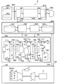
- FIG. 1 is a diagram showing a main device of a gas turbine power generator according to an embodiment of the present invention.
- the gas turbine power generation device S of the embodiment is a device having a function and an operation method for improving the power generation output by spraying hot water w4 heated by solar heat onto the air sent to the compressor 2.
- the gas turbine power generator S includes a hot water generator 700 that generates hot water w4 by solar heat, and a gas turbine power generation facility 100 that generates power by driving the gas turbine 1 with compressed exhaust gas sprayed with the hot water w4 and combustion exhaust gas. It is equipped with.
- the gas turbine power generation facility 100 includes a compressor 2 that compresses air (intake air) sprayed with hot water w4 and outputs the compressed air, a combustor 4 that combusts fuel with the compressed air supplied from the compressor 2, and a combustor.
- 4 is provided with a gas turbine 1 driven by combustion exhaust gas from 4, and a generator 3 connected to the gas turbine 1 via a gas turbine shaft 1j.
- the gas turbine power generation device S includes a hot water generator 700 that heats water to warm water w4 by solar heat, an intake air cooling chamber 5 that cools air (intake air) sent to the sucked compressor 2, and an intake air cooling chamber 5 And a spray nozzle 6 for spraying hot water w4 heated by the hot water generator 700.
- the advantage of using warm water is that spraying warm water causes the fog of warm water to drop from high temperature and pressure to atmospheric pressure, so the boiling point suddenly becomes low and boiling under reduced pressure occurs. Therefore, the sprayed fine water droplets evaporate all at once, and the fine water droplets sprayed by evaporation become further fine particles. Accordingly, since more spray water can be sprayed from the spray nozzle 6, the evaporation phenomenon is promoted, and the temperature is further lowered by the latent heat of evaporation, thereby increasing the density of the intake air.
- the mass flow rate can be further increased, and further output improvement can be achieved by spraying warm water. Further, since the sprayed fine water droplets are further finely divided, the generation of drain and rust caused by the combustion exhaust gas colliding with the turbine blades of the gas turbine 1 can be suppressed as much as possible.
- ⁇ Hot water generator 700> The hot water generator 700 that absorbs solar heat absorbs the heat from the sun into the first working fluid w1 that flows in the heat collecting pipe (not shown), and increases the temperature of the first working fluid w1 by the solar heat collecting device 701. It has.
- the heat medium oil of the first working fluid w1 and the second working fluid w2 whose temperature is increased by solar heat (hereinafter, the second working fluid w2 will be described as the heat medium oil w2) and First heat exchanger 702 that performs heat exchange in the first, second and second heat storage tanks 703 and 704 that store the heat transfer medium oil w2 that has reached a high temperature, a water supply tank 706 that stores the water w3, and a heat transfer medium
- a second heat exchanger 705 is provided that performs heat exchange between the oil w2 and the water w3 from the water supply tank 706 to obtain hot water w4 for spraying.
- the hot water generator 700 is provided with adjusting valves 711 to 718 for opening and closing the flow path of the hot water generator 700 and pumps 721 to 725 for sending the working fluid (w1, w2, w3, w4).
- the regulating valves 711 to 718 and the pumps 721 to 725 operate by receiving a control signal 130 from a control device 200 (see FIG. 2) described later.
- the working fluid w1 delivered by the pump 721 flows through a heat collecting tube (not shown) by the solar heat collector 701 and is heated by solar heat.
- heat transfer oil is used as the working fluid w1.
- the first working fluid w1 and the second working fluid w2 exemplify the case where oil (heat medium oil) is used, but the first and second working fluids w1 and w2 are heat medium oil.
- water may be used.
- the first and second working fluids w1 and w2 are preferably oils whose pressure increase is slower than water even at high temperatures.
- the first and second working fluids w1 and w2 may use a heat medium other than the heat medium oil.
- a heat medium is selected that has a gradual rise in pressure even at high temperatures and low viscosity at low temperatures.
- the heat medium oil w2 circulated by the pumps 722 and 723 rises in temperature by exchanging heat with the working fluid w1 heated by solar heat in the first heat exchanger 702.
- the heat transfer oil w2 is heated by the heat exchanger 702
- the heat medium oil w2 of a predetermined temperature can always heat the water w3 sent from the water supply tank 706 by the second heat exchanger 705 with an amount within the capacity of the heat storage tank 703.
- the feed water (water w3) fed from the feed water tank 706 to the second heat exchanger 705 by the pump 724 is heated by heat exchange with the heat transfer oil w2 in the second heat exchanger 705 and heated at a predetermined temperature. Heated to w4.
- the hot water w4 having a predetermined temperature is pressurized by the booster pump 725 and sprayed from the spray nozzle 6 into the intake cooling chamber 5.
- the regulating valves 711, 714, 717 are operated when controlling the state of the operating fluid (w1, w2, w3, w4) during operation or in an emergency.
- the regulating valve 711 is used when the temperature of the working fluid w1 heated by the solar heat collecting apparatus 701 does not reach a predetermined temperature used in the first heat exchanger 702 or when the heat in the first heat exchanger 702 is reached.
- the flow path from the solar heat collecting apparatus 701 is set to the bypass line b1 side instead of the first heat exchanger 702 side.
- the temperature of the working fluid w1 heated by the solar heat collector 701 reaches a predetermined temperature used in the first heat exchanger 702 and heat exchange is performed in the first heat exchanger 702.
- the flow path from the solar heat collecting apparatus 701 is not the bypass line b1 side but the first heat exchanger 702 side.
- the regulating valve 714 Not on the 705 side but on the bypass line b2 side.
- the second heat exchanger 705 is not the side of the bypass line b2 but the second heat exchanger 705. Let it be the heat exchanger 705 side.
- the regulating valve 717 is not on the spray nozzle 6 side but on the water supply tank 706 side. Open the flow path.
- the regulating valve 717 is not on the water supply tank 706 side. A flow path is opened on the spray nozzle 6 side.
- the regulating valves 712, 713, 715, 716 are operated when accumulating or releasing the amount of heat obtained by the solar heat collecting apparatus 700.
- the flow paths of the regulating valves 712, 713, 715, 716 are opened, and the first heat exchange tanks 703, 704 perform the first heat exchange.
- the high-temperature heat transfer oil w2 heated by the vessel 702 is stored.
- the high-temperature heat transfer oil w2 stored in the first and second heat storage tanks 703 and 704 is adjusted to the regulating valves 712, 713, 715, and 716. Is opened, discharged to the second heat exchanger 705, and the water w3 is heated.
- FIG. 2 is a diagram showing a gas turbine power generation apparatus including main components of the embodiment and an operation method thereof.
- the hot water generating device 700 of the gas turbine power generation device S and the gas turbine power generation facility 100 are operated (controlled) by the control device 200.
- An operation command to the hot water generation device 700 and the gas turbine power generation facility 100 and an operation state display of the hot water generation device 700 and the gas turbine power generation facility 100 are performed using the support tool 910.
- the gas turbine power generation facility 100 receives the control signal 150 from the control device 200 and is controlled to a desired state.
- the state quantity of each part of the gas turbine power generation facility 100 is captured (transmitted) into the control device 200 as a measurement signal 140.
- the control device 200 performs control by operating various operation ends so as to be in an appropriate operation state with respect to the power generation request based on the measurement signal 140 from the gas turbine power generation facility 100. Since this control method is based on a known technique, the relationship with the hot water generator 700 of the gas turbine power generation facility 100 will be described here.
- the adjustment valves 711 to 718 are adjusted so that the gas turbine power generation facility 100 is in an appropriate operating state, and the working fluid w1 and the heat medium are heated by the solar heat of the solar heat collector 701.
- a control signal 130 is output so as to supply the intake water cooling chamber 5 with an appropriate amount of hot water w4 having a predetermined temperature heated via the oil w2.
- the predetermined temperature is, for example, about 150 ° C., but is not limited to about 150 ° C.
- the related information database 300 stores information for use in determining the operating conditions of the gas turbine power generation facility 100 and the hot water generator 700.
- the operation information database 600 stores measurement signals 140 and 120 obtained from the gas turbine power generation facility 100 and the hot water generator 700, respectively.
- the hot water generator 700 and the gas turbine are based on information obtained from the measurement signals 120 and 140 and data necessary for determining the operating conditions of the gas turbine power generation facility 100 and the hot water generator 700.
- the operation state of the power generation facility 100 is determined (calculated).
- the data necessary for determining the operating condition includes, for example, information on sunshine data when the outside air temperature or solar heat is used. Details of these data will be described later.
- the control unit 500 receives the determination result of the operating condition determination unit 400 (input information of the determination result) and outputs an appropriate control signal 130 according to the determination result to the hot water generator 700. Based on the control signal 130, the regulating valves 711 to 718 and the pumps 721 to 725 in the hot water generator 700 are controlled. The signals (130, 150) and information generated in the control device 200 are also output to the support tool 910 as necessary.
- the determination result by the operating condition determination unit 400 and the algorithm for obtaining the control signals 130 and 150 will be described in detail later.
- a user related to the gas turbine power generation facility 100 can visually check various information regarding the gas turbine power generation facility 100 and the hot water generator 700 on the image display device 950 by using the support tool 910.
- the support tool 910 includes an external input / output interface 920, a data transmission / reception processing unit 930, and an external output interface 940.
- the support tool 910 is connected to an input device 900 that includes a keyboard 901, a mouse 902, a touch panel, and the like, and an image display device 950 that is an output device. Further, the user can access information in the control device 200 by using the support tool 910 using the input device 900.
- the input signal 800 generated by the input device 900 is received by the support tool 910 via the external input / output interface 920.
- information (signal) 210 from the control device 200 to the support tool 910 is also taken in (received) by the external input / output interface 920.
- information (signal) 210 from the support tool 910 to the control device 200 is also taken into (received) by the control device 200 via the external input / output interface 920.
- the data transmission / reception processing unit 930 processes the input signal 801 according to the information of the input signal 800 generated by the input device 900 from the user, and transmits it to the external output interface 940 as the output signal 802.
- An output signal 803 from the external output interface 940 based on the output signal 802 is displayed on the image display device 950.
- the output signal 803 may be output to an output file, printed on a form by a printer (not shown), or output to another system and processed by another system.
- the driving condition determination data and the measurement signals 120 and 140 stored in the related information database 300 and the driving information database 600 will be described. First, information required when the driving condition determination unit 400 determines the driving condition will be described.
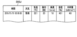
- FIG. 3A is a diagram showing an actual measurement data table 300J.
- the measured value data table 300J in FIG. 3A is data stored in the related information database, and records information on measured values of the climatic state.
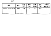
- FIG. 3B is a diagram showing a predicted value data table 300Y.
- the predicted value data table 300Y of FIG. 3B is data stored in the related information database, and information on predicted values of the climatic state is recorded.
- the measured value and the predicted value are both the time (time), weather, temperature (° C.), wind direction (degree), wind speed (m / s), humidity ( %), The amount of solar radiation (kW / m 2 ) and the like are stored. Further, the predicted value data table 300Y stores the predicted temperature of the hot water w4 described later.
- the period of time (time) to be measured is arbitrarily determined by the measurable time width.
- the weather is expressed using 15 types sent to the general public by the Japan Meteorological Agency.
- the wind direction (degree) is generally 16 azimuths, but the international style uses 360 azimuths expressed by dividing 360 degrees in the clockwise direction with true north as a reference.
- 360 azimuths are represented. However, in the case of 16 azimuths, if a ratio of 22.5 degrees is given to each azimuth, it can be numerically expressed in 360 azimuth degrees.
- Actual measured values are stored in the actual measurement data table 300J shown in FIG. 3A.
- Each numerical value is stored in the predicted value data table 300Y shown in FIG. 3B based on, for example, a calculation result in the prediction model and distribution data.
- each numerical value may be currently distributed every hour, but in other cases, a model for calculating a predicted value based on past data is required.
- This prediction model includes, for example, a meso-meteorological model (Weather Research and Forecasting model: WRF model) which is a model for predicting an atmospheric state based on a physical formula.
- WRF model Weather Research and Forecasting model
- this model since it is necessary to make a setting for forecasting a desired area, there is also a simple method of obtaining using a regression equation or the like based on past data.
- any method may be used.
- FIG. 4 is a diagram showing information (data) stored in the driving information database 600.
- the PID number in the first line is a unique number assigned to each measurement value so that data stored in the operation information database 600 can be easily used.
- the alphabet below the PID number is a symbol indicating the measurement target.
- the flow rate value F of the working fluid w1 heated by the solar heat collecting device 701, the temperature value T of the working fluid w1, the pressure value P of the working fluid w1, the power generation output value E of the generator 3, and the combustor 4 The concentration value D of NOx contained in the combustion exhaust gas, the temperature of the hot water w4, and so on.
- data is stored at a cycle of 1 second, but the sampling cycle of data collection differs depending on the target gas turbine power generation facility 100.
- FIG. 5 shows the fluid discharged from the solar heat collector 701 (first) using the data stored in the predicted value data table 300Y (see FIG. 3B) stored in the related information database 300 shown in FIG. It is a figure which shows the model which estimates the temperature of the working fluid w1).
- the operating condition determination unit 400 estimates the temperature of the fluid (first working fluid w1) discharged from the solar heat collecting apparatus 701 from the heat of the fluid (first working fluid w1). This is to obtain control information for setting the temperature of the hot water w4 used for spraying obtained to a predetermined value.
- This model has an input layer, an intermediate layer, and an output layer, and each layer has multiple nodes. These nodes are linked from the input layer to the output layer, and a weighting coefficient (for example, ⁇ 1 to ⁇ n: n is the number of connections) indicating the strength of the link is set. That is, there are as many weighting coefficients as the number of connections between nodes.
- a weighting coefficient for example, ⁇ 1 to ⁇ n: n is the number of connections
- This model is called a neural network, and simulates a human cranial nerve network.
- this model By giving an input value to this model and adjusting the weighting coefficient so that a desired output value for the input value is output, the correlation of the input value can be expressed as a model. This is called learning.
- an input value can be input to the model, and an output value can be estimated based on the correlation obtained by the input value at that time.
- the function set for each node generally uses an exponential function called a sigmoid function, but is not limited thereto.
- many algorithms have been devised that appropriately adjust the weighting factors (the above-mentioned ⁇ 1 to ⁇ n) during learning.
- the back propagation method is used.
- the back-propagation method is referred to as a back-propagation method because it is a method in which a virtual output value is assigned and a weighting factor representing a weight affecting the virtual output value is obtained retrospectively from the virtual output value.
- the method for estimating the temperature of the fluid (working fluid w1) discharged from the solar heat collecting apparatus 701 may be another method such as a least square method other than the illustrated back-propagation method, and the fluid (working fluid w1). Of course, the method is not limited as long as the temperature can be estimated.
- the operating condition determination unit 400 predicts the temperature of the hot water w4 using data stored in the predicted value data table 300Y (see FIG. 3B).
- the measured value data table 300J (see FIG. 3A), information on the measurement signals 120 and 140, information on the driving information database 600, and the like are used as necessary.
- the predicted temperature of the hot water w4 is recorded by the operating condition determination unit 400 in the predicted value data table 300Y or the storage unit of the work area. Then, the controller 500 uses the predicted temperature of the hot water w4 to store a necessary amount of heat in the first and second heat storage tanks 703 and 704. For example, when the temperature is predicted to be low or the amount of solar radiation is predicted to be small, the heat amount of the heat transfer oil w2 is accumulated in the first and second heat storage tanks 703 and 704. On the other hand, when the temperature is predicted to be high or the amount of solar radiation is predicted to be large, the amount of heat of the heat transfer oil w2 is accumulated in the first and second heat storage tanks 703 and 704 to a small extent.
- FIG. 6 is a flowchart showing the processing operation in the operating condition determination unit 400.
- the processing operation in the operation condition determination unit 400 shown in FIG. 2 is any one of a prediction mode for predicting the operation of the gas turbine power generation facility 100 and the hot water generator 700, an actual operation start mode, an operation mode, and a stop mode. This is a process of distributing the above.
- the prediction mode, the start mode, the operation mode, and the stop mode (operation conditions) are input from the support tool 910 by the user.
- step S401 of FIG. 6 it is determined whether or not the operation condition prediction mode of the gas turbine power generation equipment 100 and the hot water generator 700 is set. If it is the prediction mode (Yes in Step S401), the process proceeds to Step S402, while if it is not the prediction mode (No in Step S401), the process proceeds to Step S406.
- the setting information of heat storage enablement, start mode, operation mode, and stop mode obtained in the flow of FIG. 6 is input to the control unit 500 in the control device 200 of FIG.
- the control unit 500 in FIG. 2 controls the regulating valves 711 to 718 and the pumps 721 to 725 in the hot water generator 700 based on information from the operation condition determination unit 400 and the operation information database 600.
- the control unit 500 in FIG. 2 controls the regulating valves 711 to 718 and the pumps 721 to 725 in the hot water generator 700 based on information from the operation condition determination unit 400 and the operation information database 600.
- start mode When the start mode is set to “1” (start mode is ON), the bypass line b1 side of the regulating valve 711 shown in FIG. 2 is opened first, and the solar heat collector 701 does not pass through the heat exchanger 702. A circulation loop passes through the bypass line b1.
- the working fluid w1 is circulated by the pump 721, and the temperature is raised until the temperature of the working fluid w1 flowing into the first heat exchanger inlet 702i reaches a preset temperature.
- An unillustrated temperature sensor for measuring the temperature of the working fluid w1 is disposed upstream of the regulating valve 711.
- the bypass line b2 is opened by operating the adjustment valve 714.
- the regulating valves 712, 713, and 715 are opened so that the heat transfer oil w2 can flow into the first heat exchanger 702. Whether or not the heat transfer oil w2 is allowed to flow through the second heat storage tank 704 depends on the control state of the hot water generator 700.
- the adjustment valve 715 is opened to the second heat storage tank 704 side, and the adjustment valve 716 is also opened.
- the pumps 722 and 723 are operated, and the heat transfer oil w2 flows into the first heat exchanger 702.
- the bypass line b1 is closed by the operation of the regulating valve 711, and the working fluid w1 flows through the first heat exchanger 702.
- the first heat exchanger 702 starts heat exchange between the working fluid w1 heated to the set temperature by solar heat and the heat transfer oil w2.
- the current state is maintained until the temperature of the heat transfer oil w2 flowing into the second heat exchanger inlet 705i reaches a preset temperature.
- a temperature sensor (not shown) that measures the temperature of the heat transfer oil w2 is disposed upstream of the regulating valve 714.
- the bypass line b3 through which the water w3 flows is opened by operating the adjustment valve 717, and the pumps 724 and 725 are operated.
- the adjustment valve 718 is also opened, and the water w3 supplied from the water supply tank 706 flows into the second heat exchanger 705 and the bypass line b3.
- the bypass line b ⁇ b> 2 is closed by the operation of the regulating valve 714, and the working fluid heat transfer oil w ⁇ b> 2 flows into the second heat exchanger 705.
- the temperature of the water w3 supplied from the water supply tank 706 is raised by heat exchange with the heat transfer oil w2 in the second heat exchanger 705. Spraying is possible when the temperature and pressure of the water w3 on the outlet side 725o of the pump 725 reach a preset temperature and pressure.
- a temperature sensor and a pressure sensor (not shown) for measuring the temperature and pressure of the water w3 are disposed downstream of the outlet side 725o of the pump 725.
- the adjustment valve 717 is operated to close the bypass line b3 and shift to the operating state. Then, a signal indicating the operation mode is sent to the support tool 910.
- operation mode when the operation mode is set to “1” (operation mode is ON), the operation is performed so that the state of the hot water 4 immediately before the spray nozzle 6 becomes a desired pressure and temperature.
- a pressure sensor and a temperature sensor (not shown) for measuring the pressure and temperature of the hot water w4 are disposed immediately before the spray nozzle 6, respectively.
- a pressure sensor (not shown) and a temperature sensor for measuring the pressure and temperature of the hot water w4 are not provided immediately before the spray nozzle 6, respectively.
- a temperature sensor and a pressure sensor (not shown) downstream of the outlet side 725o of the pump 725 measure the temperature and pressure of the hot water w4, respectively.
- the working fluid w1 at the inlets 702i and 705i of the first and second heat exchangers 702 and 705, The set value of each temperature of the heat transfer oil w2 is determined.
- the temperature of the heat transfer oil w2 at the inlet (705i) on the high temperature side of the second heat exchanger 705 is a set value, and the temperature of the heat transfer oil w2 at the outlet (705o) is a temperature considering the heat loss after heat exchange.
- the control valves 712 and 713 and the pump 723 of the first heat storage tank 703 of the high-temperature tank are controlled.
- the temperature of the working fluid w1 at the inlet (702i) of the first heat exchanger 702 and the temperature of the working fluid w1 at the outlet (702o) are controlled in the same way.
- stop mode When the stop mode is set to “1” (stop mode is ON), all the control valves 711, 714, 717 are operated to open all the bypass lines b1, b2, b3, and then all the pumps 721 to 725 is stopped.
- the opening degree of each of the regulating valves 712 and 713 is operated to store an excessive amount of heat for stable operation of the gas turbine power generation facility 100.
- the heat transfer oil w2 of the working fluid in the first heat storage tank 703 flows into the second heat exchanger 705, but the working fluid at the inlet 702i of the first heat exchanger 702
- the control valves 712 and 713 are controlled so that the temperature of the heat transfer oil w2 flowing into the inlet (705i) of the second heat exchanger 705 becomes a predetermined set temperature (constant) based on the same concept as the constant temperature control of w1. Operate each opening.
- the second heat storage tank 704 operates the opening degree of each of the adjustment valves 715 and 716.
- the adjustment valve 714 causes the heat medium oil w2 to be
- the heat medium oil w2 is flowed to the bypass line b2 without flowing to the heat exchanger 705, and the temperature of the heat transfer oil w2 is transferred to the inlet (705i) of the second heat exchanger 705 by heat exchange in the first heat exchanger 702. Heat to set temperature.
- the adjustment valve 714 closes the bypass line b2 to change the heat transfer oil w2 Flow to the second heat exchanger 705. Even when it is determined that the temperature of the heat transfer oil w2 flowing to the inlet (705i) of the second heat exchanger 705 does not reach the set temperature, the inlet (705i) of the second heat exchanger 705 You may comprise so that it may flow.
- FIG. 7 to 10 show examples of screens G1, G2, G3, and G4 displayed on the image display device 950 of FIG.
- the user uses the keyboard 901 and the mouse 902 shown in FIG. 2 to perform operations such as selecting a button on the screens G1 to G4 by pressing a button or inputting a parameter value in a blank area.
- Various information of the gas turbine power generator S is displayed.
- FIG. 7 shows a data processing device GUI screen G1 of the initial screen displayed on the image display device 950.
- the user displays the data processing device GUI screen G1 on the image display device 950, moves the cursor 953 using the mouse 902 (see FIG. 2), and is necessary from the operation state display button 951 or the trend display button 952 ( A desired button is selected by clicking with the mouse 902.
- a desired operation state display screen operation state display screen G2 in FIG. 8) or a trend display screen (trend display setting screen G3 in FIG. 9) can be displayed.
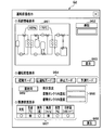
- FIG. 8 shows an operation state display screen G2 which is an operation state display screen.
- the operation state display button 951 is clicked on the data processing device GUI screen G1 (see FIG. 7)
- the operation state display screen G2 of FIG. 8 is displayed.
- the system information display field 961 of the operation state display screen G2 the user inputs the time desired to be displayed in the time input field 962.
- the display button 963 By clicking (pressing) the display button 963, various states at the input time are displayed in the system information display field 961.
- FIG. 8 shows a case where the opening degree of the regulating valve 711 and the temperature of the heat transfer oil w2 at the inlet (705i) of the second heat exchanger 705 are displayed.
- the user selects one of a start mode, an operation mode, a stop mode, and a prediction mode. Then, the selected mode is highlighted.
- FIG. 8 shows a case where the operation mode is highlighted.
- the selection signal is transmitted to the driving condition determination unit 400 (see FIG. 2) via the support tool 910.
- the support tool 910 receives the operation mode signal (information 210) from the operation condition determination unit 400 of the control device 200 that has received the measurement signals 120 and 140.
- the operation mode column in this screen G2 is highlighted (lighted).
- the heat storage possibility 965 is highlighted (lighted).
- the prediction mode is selected on the operation state display 964, the estimated temperature of the first working fluid w1 is displayed as the estimated temperature in the 966 column.
- the temperature in the heat storage tank 1 in the column 966 indicates the temperature of the heat transfer oil w2 in the first heat storage tank 703, and the temperature in the heat storage tank 2 indicates the temperature of the heat transfer oil w2 in the second heat storage tank 704.
- Each item of the state of the outside air in each mode is displayed in the related information display column 967.
- the return button 968 By clicking (depressing) the return button 968 on the operation state display screen G2, it is possible to return to the data processing device GUI screen G1 of FIG.
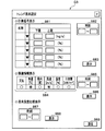
- FIG. 9 is a trend display setting screen G3 that is a setting screen for displaying trends such as measured values and various specifications over time on the image display device 950.
- the trend display button 952 is clicked (pressed) on the data processing device GUI screen G1 in FIG. 7, the trend display setting screen G3 in FIG. 9 is displayed.
- the user inputs the measurement signal 120, 140 or the operation signals 130, 150 to be displayed on the image display device 950 together with the range (upper / lower) in the input field.
- FIG. 9 shows a case where the name of the measurement signal display field 981 is selected and displayed using a pull-down menu.
- the time input field 982 the time zone in which the signal input in the measurement signal display field 981 is to be displayed is input.
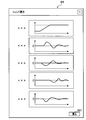
- a trend display screen G4 (see FIG. 10) showing a trend graph of data input in the measurement signal display field 981 and the time input field 982 is displayed on the image display device 950. Is displayed.
- the user who views the desired trend graph can return to the screen of FIG. 9 by clicking (pressing) the return button 991 on the trend display screen G4 (see FIG. 10).
- any of the weather, temperature, wind direction, wind speed, humidity, and solar radiation in the state of the outside air is selected.
- FIG. 9 shows a case where temperature and wind speed are selected.
- a time zone in which the item selected in the related information display field 984 is to be displayed is input to the time input field 985.
- the display button 986 is clicked, the selected information is retrieved from the related information database 300 (see FIG. 2) via the support tool 910, and the trend graph on the trend display screen G4 (see FIG. 10) is displayed as an image. It is displayed on the display device 950.
- the weather in the related information display column 984 is expressed using 15 types transmitted (announced) to the general public by the Japan Meteorological Agency as described above. That is, a number is assigned according to each type of weather, and this is displayed as a trend. That is, numbers are sequentially assigned up to 14, such as 0 for clear weather, 1 for clear weather, and 2 for light cloudiness. Note that symbols such as ⁇ (cloudy), ⁇ (rainy), and pictograms may be displayed.
- the predicted hot water temperature and the actual hot water temperature are compared and displayed.
- the user inputs a time zone to be compared in the time input field 987 and clicks (presses) the display button 988, a trend for comparing and displaying the predicted hot water temperature and the actual hot water temperature on the trend display screen G4 in FIG.
- the graph is displayed on the image display device 950.
- the user can return to the data processing device GUI screen G1 of FIG. 7 by clicking (pressing) the return button 989 on the trend display setting screen G3 of FIG.
- the gas turbine power generation equipment 100 since the warm water w4 heated using the solar heat is sprayed on the air which the compressor 2 suck
- a database is exemplified as the storage unit.
- a temporary file or a work area may be used as long as the storage unit can store various data, and the mode is not limited as long as data can be stored.
- the various storage units described in the embodiment may be divided and configured, and the operating condition determination unit 400 and the control unit 500 may be configured separately or may be integrated into one unit. May be.
Landscapes
- Engineering & Computer Science (AREA)
- Chemical & Material Sciences (AREA)
- Combustion & Propulsion (AREA)
- Mechanical Engineering (AREA)
- General Engineering & Computer Science (AREA)
- Engine Equipment That Uses Special Cycles (AREA)
- Heat-Pump Type And Storage Water Heaters (AREA)
Abstract
L'invention porte sur un dispositif de production d'électricité à turbine à gaz et sur un procédé de fonctionnement de celui-ci, à l'aide desquels la puissance développée peut être améliorée par une pulvérisation d'eau chauffée obtenue avec l'énergie thermique de la chaleur solaire, et à l'aide desquels il est possible d'obtenir un fonctionnement stable. Ce dispositif de production d'électricité à turbine à gaz (S) comporte : un compresseur (2) qui comprime de l'air; une chambre de combustion (4) qui brûle un combustible et l'air comprimé issu du compresseur (2); une turbine à gaz (1) qui est entraînée par le gaz de combustion de la chambre de combustion (4); un dispositif de production d'électricité (3) qui est relié à la turbine à gaz par un arbre (1j) et qui est entraîné par la rotation de la turbine à gaz (1); un échangeur de chaleur (705) qui échange de la chaleur avec un milieu caloporteur (w2) qui a été chauffé à l'aide de la chaleur solaire; des réservoirs de stockage de chaleur (703, 704) qui stockent le milieu caloporteur (w2); une première ligne de dérivation (b3) qui contourne un trajet de circulation qui se trouve sur le côté à chauffer et qui est formé avec l'échangeur de chaleur (705); une première soupape de réglage (717) qui règle le débit volumique de la première ligne de dérivation (b3); et une chambre de refroidissement d'air d'aspiration (5) servant à pulvériser dans l'air situé dans le compresseur (2), au moyen de buses de pulvérisation (6), de l'eau chauffée (w4) qui a été chauffée par l'échangeur de chaleur (705).
Priority Applications (2)
| Application Number | Priority Date | Filing Date | Title |
|---|---|---|---|
| JP2013542749A JP5766295B2 (ja) | 2011-11-09 | 2011-11-09 | ガスタービン発電装置およびその運転方法 |
| PCT/JP2011/075833 WO2013069111A1 (fr) | 2011-11-09 | 2011-11-09 | Dispositif de production d'électricité à turbine à gaz et procédé de fonctionnement de celui-ci |
Applications Claiming Priority (1)
| Application Number | Priority Date | Filing Date | Title |
|---|---|---|---|
| PCT/JP2011/075833 WO2013069111A1 (fr) | 2011-11-09 | 2011-11-09 | Dispositif de production d'électricité à turbine à gaz et procédé de fonctionnement de celui-ci |
Publications (1)
| Publication Number | Publication Date |
|---|---|
| WO2013069111A1 true WO2013069111A1 (fr) | 2013-05-16 |
Family
ID=48288701
Family Applications (1)
| Application Number | Title | Priority Date | Filing Date |
|---|---|---|---|
| PCT/JP2011/075833 Ceased WO2013069111A1 (fr) | 2011-11-09 | 2011-11-09 | Dispositif de production d'électricité à turbine à gaz et procédé de fonctionnement de celui-ci |
Country Status (2)
| Country | Link |
|---|---|
| JP (1) | JP5766295B2 (fr) |
| WO (1) | WO2013069111A1 (fr) |
Cited By (3)
| Publication number | Priority date | Publication date | Assignee | Title |
|---|---|---|---|---|
| CN105089955A (zh) * | 2014-05-09 | 2015-11-25 | 亮源工业(以色列)有限公司 | 生成电能的方法和系统、存储日射热量的方法和系统 |
| JP2021085574A (ja) * | 2019-11-26 | 2021-06-03 | 株式会社神鋼環境ソリューション | 熱利用システム及びその起動方法 |
| CN116804381A (zh) * | 2023-06-29 | 2023-09-26 | 米奇科技(北京)有限公司 | 一种液态空气储能发电系统及设备 |
Citations (3)
| Publication number | Priority date | Publication date | Assignee | Title |
|---|---|---|---|---|
| JPS57146067A (en) * | 1981-03-06 | 1982-09-09 | Agency Of Ind Science & Technol | Solar heat-utilizing power plant |
| EP1820965A1 (fr) * | 2006-02-17 | 2007-08-22 | Siemens Aktiengesellschaft | Méthode et dispositif pour régler la production énergétique dans une centrale thermique solaire |
| JP2009041567A (ja) * | 2007-08-07 | 2009-02-26 | General Electric Co <Ge> | ガスタービンのスプレー入口温度サプレッサ用の圧力を供給するための方法及び装置 |
Family Cites Families (1)
| Publication number | Priority date | Publication date | Assignee | Title |
|---|---|---|---|---|
| JPS58101228A (ja) * | 1981-12-10 | 1983-06-16 | Mitsubishi Gas Chem Co Inc | ガスタ−ビンサイクル |
-
2011
- 2011-11-09 JP JP2013542749A patent/JP5766295B2/ja active Active
- 2011-11-09 WO PCT/JP2011/075833 patent/WO2013069111A1/fr not_active Ceased
Patent Citations (3)
| Publication number | Priority date | Publication date | Assignee | Title |
|---|---|---|---|---|
| JPS57146067A (en) * | 1981-03-06 | 1982-09-09 | Agency Of Ind Science & Technol | Solar heat-utilizing power plant |
| EP1820965A1 (fr) * | 2006-02-17 | 2007-08-22 | Siemens Aktiengesellschaft | Méthode et dispositif pour régler la production énergétique dans une centrale thermique solaire |
| JP2009041567A (ja) * | 2007-08-07 | 2009-02-26 | General Electric Co <Ge> | ガスタービンのスプレー入口温度サプレッサ用の圧力を供給するための方法及び装置 |
Cited By (4)
| Publication number | Priority date | Publication date | Assignee | Title |
|---|---|---|---|---|
| CN105089955A (zh) * | 2014-05-09 | 2015-11-25 | 亮源工业(以色列)有限公司 | 生成电能的方法和系统、存储日射热量的方法和系统 |
| JP2021085574A (ja) * | 2019-11-26 | 2021-06-03 | 株式会社神鋼環境ソリューション | 熱利用システム及びその起動方法 |
| JP2024019206A (ja) * | 2019-11-26 | 2024-02-08 | 株式会社神鋼環境ソリューション | 熱利用システム |
| CN116804381A (zh) * | 2023-06-29 | 2023-09-26 | 米奇科技(北京)有限公司 | 一种液态空气储能发电系统及设备 |
Also Published As
| Publication number | Publication date |
|---|---|
| JP5766295B2 (ja) | 2015-08-19 |
| JPWO2013069111A1 (ja) | 2015-04-02 |
Similar Documents
| Publication | Publication Date | Title |
|---|---|---|
| CN104632311B (zh) | 蒸汽涡轮成套设备启动控制装置 | |
| JP5400969B2 (ja) | ガスタービンシステム、ガスタービンシステムの制御装置及びガスタービンシステムの制御方法 | |
| Han et al. | Assessment of off-design performance of a small-scale combined cooling and power system using an alternative operating strategy for gas turbine | |
| JP5399565B2 (ja) | 太陽熱利用コンバインドサイクル発電プラント | |
| US20090125152A1 (en) | Method of measurement, control, and regulation for the solar thermal hybridization of a fossil fired rankine cycle | |
| EP2818665A1 (fr) | Système de turbine à gaz assisté par la chaleur solaire | |
| CN106321161A (zh) | 启动控制装置 | |
| Camporeale et al. | Part load performance and operating strategies of a natural gas—biomass dual fueled microturbine for combined heat and power generation | |
| Abrosimov et al. | Extensive techno-economic assessment of combined inverted Brayton–Organic Rankine cycle for high-temperature waste heat recovery | |
| JP5766295B2 (ja) | ガスタービン発電装置およびその運転方法 | |
| Wei et al. | Performance of a novel natural draft hybrid cooling system with serial airside heat exchange | |
| US20130139517A1 (en) | Solar Assisted Gas Turbine System | |
| AU2011342551B2 (en) | Cooling system | |
| CN113191566A (zh) | 热泵梯级供热机组最佳运行方式的在线确定系统及方法 | |
| Villa et al. | Techno-economic and Exergoeconomic Analysis of a micro cogeneration system for a residential use | |
| Gabrielli et al. | Off-design modeling and operational optimization of trans-critical carbon dioxide heat pumps | |
| CN109885855A (zh) | 考虑机组特性的冷-热-电三联供能源站稳态调度方法 | |
| JP5514322B2 (ja) | ガスタービン発電装置、ガスタービン発電システムおよびその制御方法 | |
| Moon et al. | Simulation of optimizing the partial load performance of a gas turbine combined cycle using exhaust heat recuperation and inlet bleed heating | |
| Reuter et al. | Impact of HRSG characteristics on open volumetric receiver CSP plant performance | |
| JP5422057B2 (ja) | ガスタービンシステム及びその制御方法 | |
| US20140013757A1 (en) | Solar Thermal Gas Turbine System | |
| De Paepe et al. | Control Strategy Development for Optimized Operational Flexibility From Humidified Microgas Turbine: Saturation Tower Performance Assessment | |
| JP2012140882A (ja) | 太陽熱複合発電設備の発電量算定方法および装置 | |
| Yang et al. | Green heating: Theory and practice |
Legal Events
| Date | Code | Title | Description |
|---|---|---|---|
| 121 | Ep: the epo has been informed by wipo that ep was designated in this application |
Ref document number: 11875266 Country of ref document: EP Kind code of ref document: A1 |
|
| ENP | Entry into the national phase |
Ref document number: 2013542749 Country of ref document: JP Kind code of ref document: A |
|
| NENP | Non-entry into the national phase |
Ref country code: DE |
|
| 122 | Ep: pct application non-entry in european phase |
Ref document number: 11875266 Country of ref document: EP Kind code of ref document: A1 |