EP1821119A2 - Dispositif d'ancrage et dispositif de détection pour un appareil de mesure sismique - Google Patents
Dispositif d'ancrage et dispositif de détection pour un appareil de mesure sismique Download PDFInfo
- Publication number
- EP1821119A2 EP1821119A2 EP07003162A EP07003162A EP1821119A2 EP 1821119 A2 EP1821119 A2 EP 1821119A2 EP 07003162 A EP07003162 A EP 07003162A EP 07003162 A EP07003162 A EP 07003162A EP 1821119 A2 EP1821119 A2 EP 1821119A2
- Authority
- EP
- European Patent Office
- Prior art keywords
- anchoring
- sensor
- anchoring device
- sensor device
- tube
- Prior art date
- Legal status (The legal status is an assumption and is not a legal conclusion. Google has not performed a legal analysis and makes no representation as to the accuracy of the status listed.)
- Withdrawn
Links
Images
Classifications
-
- G—PHYSICS
- G01—MEASURING; TESTING
- G01V—GEOPHYSICS; GRAVITATIONAL MEASUREMENTS; DETECTING MASSES OR OBJECTS; TAGS
- G01V1/00—Seismology; Seismic or acoustic prospecting or detecting
- G01V1/16—Receiving elements for seismic signals; Arrangements or adaptations of receiving elements
Definitions
- the invention relates to an anchoring device with the features of the preamble of claim 1, which is provided for positioning a seismic sensor device.
- the invention further relates to a sensor device for detecting seismic signals having the features of the preamble of claim 10 and a seismic measuring device having an anchoring and a sensor device.
- a seismic sensor contains at least one geophone or at least one accelerometer.
- For direction-selective vibration measurements are several Geofone or accelerometer, z.
- Out CH 689 191 A5 is a seismic measuring device in which a plurality of seismic sensors are arranged in a tube which is insertable for receiving seismic vibrations in a bore.
- This measuring device is intended in particular for underground seismic measurements outside the loosened edge zone of a tunnel or tunnel wall.
- the tube has a rectangular profile in which one or more accelerometers are releasably attached under the action of a spring bias or a magnet.
- the sensors can advantageously be reused after the measurement with this technique. Disadvantages can, however, arise in relation to the sensitivity and the mechanical coupling of the sensors to the environment.
- the rectangular tube profile produced in the holes with a typical circular drill profile relatively large dead volume, which must be filled with great effort with cement.
- EP 753 161 B1 is a geological drill described in the rod an acoustic sensor can be used.
- the acoustic sensor is detachably connected to the linkage and intended to receive seismic vibrations from the environment during breaks of the drill.
- the coupling of the acoustic sensor to the drill string requires a complicated mechanical structure, which adversely affects a transmission of the vibrations from the environment to the sensor.
- the conventional technique is therefore characterized by a low sensitivity and ineffective mechanical coupling of the sensors to the environment.
- Another disadvantage is that the drill string does not provide a secure anchoring of the acoustic sensor in the surrounding geological formation. The recording of the seismic oscillations depends on the accidental operating condition that the drill takes during the break in operation.
- a significant disadvantage of the conventional method is that the position of the sensor is not exactly defined and that the transmission of measuring signals causes considerable practical difficulties.
- the object of the invention is to provide an improved anchoring device with which the disadvantages of the conventional techniques for positioning a seismic sensor device are avoided and in particular enables a reliable yet releasable anchoring of the sensor device with an improved vibration coupling to the environment.
- the anchoring device should be characterized in particular by a simplified structure and easy handling when inserting the sensor device.
- the object of the invention is also to provide an improved sensor device for detecting seismic signals, with which the disadvantages of the conventional techniques are overcome and in particular for a reliable power transmission solvable with the anchoring device can be connected.
- the sensor device should have a cost-effective design and, if necessary, be separable from the anchoring device with little effort.
- the object of the invention is also to provide an improved seismic measuring device with which the disadvantages of the conventional techniques are avoided and in which the required fixed connection of sensors with the environment, eg the surrounding rock, is guaranteed in all measuring positions and under all measuring conditions ,
- the measuring device should be distinguished, in particular, by an improved releasable connection of the anchoring device and the sensor device, with which the quality of the coupling, the safety of the positioning of sensors and the reproducibility of measured values are unimpaired.
- the invention is based on the general technical teaching of releasably fixing a sensor device to provide an anchoring device with an anchoring tube, which has a coupling device for producing a screw connection of the sensor device to the anchoring tube.
- a threaded region (so-called tube threaded portion) is provided, on which the sensor device can be screwed into the anchoring tube.
- the anchoring device is a positive and / or non-positive connection of the sensor device with the anchoring tube with a comparison with the conventional connection techniques (spring element, magnetic coupling) allows considerably simplified construction.
- a single internal thread is sufficient to reliably fix a sensor device, which optionally comprises a plurality of sensors, and to position it in a clearly reproducible manner.
- the inventors have found that with the screw a reliable positive and / or positive connection can be realized, which is surprisingly given not only in the axial direction of the screw, but also in deviating, radial directions.
- the screw connection meets the high requirements in the transmission of mechanical vibration signals from the environment to a arranged in the anchoring device sensor device.
- the screw connection between the anchoring device and the sensor device in particular a positive connection is formed.
- the positive connection can be dispensed with in conventional techniques frictional connections by spring preload or magnetic force without having to accept any adverse effects on the power transmission in purchasing. Therefore, the screw is also referred to as positive.
- the motive force and the biasing force are at an angle of 90 ° to each other.
- wedge forces screw act, whereby the selected shape of the wedge dominates (friction angle> wedge angle).
- the screw is preferably formed with a round thread, which is characterized advantageously by low positioning errors and high insensitivity to dirt.
- the anchoring device is adapted to be fixed in a geological structure, in particular in mining, rock or tunnel construction, or a building, in particular in the foundation or solid construction fixed.
- the anchoring device is intended to remain there permanently after introduction and attachment in the geological structure or structure.
- a sensor device for detecting seismic signals which has on a rod-shaped carrier part a sensor part with a housing which has a threaded region (so-called sensor thread region) for producing a screw connection with a tubular Anchoring device has.
- the sensor part comprises at least one seismic sensor. All belonging to the sensor part seismic sensors are materially connected to the housing of the sensor part.
- the housing of the sensor part comprises a sensor housing of a single seismic sensor or an additional receiving housing in which several, eg three seismic sensors are arranged cohesively, for example glued, are.
- the housing has, as a sensor thread area, an external thread with which the sensor device can be screwed in positive and / or non-positive manner into an inner receptacle of a pipe which forms the anchoring device.
- the sensor device is adapted to be inserted into the anchoring device according to the abovementioned first aspect of the invention.
- the sensor part is connected via the screw directly to the anchoring tube, which is set up for permanent fixation in the geological structure or the structure.
- Rock or a structure advantageously has a considerably simplified construction, in which in particular components for interaction with the coupling device provided in a conventional anchoring device, such as e.g. can be dispensed with pads for spring elements or on magnetic materials.
- the sensor device according to the invention can with little effort with conventional sensors, such. Geophones and / or accelerometers.
- the sensor device is characterized by a simplified handling when inserted into an anchoring device, in particular using the carrier part for screwing the sensor part into the anchoring device and when removing the sensor device for reuse.
- a seismic measuring device comprising the anchoring device according to the invention and the sensor device according to the invention. It is created a two-part construction with the anchoring tube of the anchoring device as a tubular shell part and the sensor device as an inner part.
- a measuring arrangement, for. As in tunneling may include multiple anchoring and sensor devices in practice.
- the stated object is achieved by a seismic measuring method in which seismic oscillations in a geological structure or a structure are detected with the seismic measuring device.
- the anchoring device according to the invention is introduced into the geological structure or structure and permanently fixed there. The fixation takes place, for example, by gluing or cementing.
- the sensor device can be inserted into the anchoring device.
- the anchoring device can be introduced without the sensor device into the geological structure or the structure. In the latter case, the sensor device according to the invention is inserted into the anchoring device in a second step.
- the sensor device is screwed into the anchoring device, wherein the sensor part is positively and / or non-positively coupled to the anchoring device.
- the detection of seismic vibrations as is conventional measurement methods, z. B. from the application of in DE 198 52 455 A1 described sensors is known.
- the receptacle is arranged with the tube threaded portion where the position of the sensors is desired, then results in an optimal sensor coupling.
- the receptacle is arranged with the tube threaded portion at a tube end of the anchoring tube.
- the anchoring device comprises a unilaterally closed anchoring tube, in which the receptacle with the tube threaded portion in the form of an internal thread, preferably a round thread, is provided adjacent to the closed tube end.
- the sensor part in particular the housing with the external thread, sets when screwing with its end face on the closed end of the tube.
- a tension in the thread is achieved, which guarantees the positive connection between the end face and the thread flanks of the housing and sensor part and thus increases an effect corresponding to a frictional connection between the sensor part and the environment.
- the pipe end has a tip.
- a tip member which is provided by a tapered shape of the anchor pipe at the pipe end or a pipe end, e.g. cone-shaped or pyramid-shaped component is formed.
- the tip element can be formed at an oblique angle. In this case, the tip of the tip element is outside the axis of the anchoring tube.
- a provided on the pipe end component sharp-edged, z. B. be formed with a cutting edge, thereby advantageously opening an adhesive cartridge, z. B. is simplified by cutting.
- the anchoring tube thus has the shape of a straight circular cylinder, of which a pipe end is preferably closed with the tip element. At the pipe end with the tip element, the receptacle for the sensor device is provided.
- the anchoring tube has an engagement element for attaching a tool and / or an external thread for attaching an anchor nut at the end opposite the tip element.
- a rotation of the anchoring device is made possible in the borehole, z. B. to facilitate the introduction of the anchoring device in the well or to mix a binder in the borehole.
- the external thread for receiving an anchor nut anchoring device advantageously receives a double function on the one hand for releasable positioning of the sensor device and on the other hand as a wall anchor, which is provided in a conventional manner for stabilizing a structure, such as an underground tunnel wall or a structure.
- the tube threaded portion in the anchoring tube has a milled internal thread, in particular internal round thread, then there are advantages for the reliable frictional coupling of the sensor device with an optimized vibration line in all three spatial directions.
- the sensor part is arranged with the at least one seismic sensor at one end of the rod-shaped carrier part.
- the sensor part with the carrier part advantageously up to a Recording be introduced at the pipe end of an anchoring device according to the invention.
- the sensor part is detachably connected to the carrier part, there are advantages for the adaptation of the sensor device to anchoring devices with different axial lengths and for the reusability of the carrier part for inserting sensor parts into different anchoring devices.
- the support member is preferably made of a fiber composite material, for. B. glass fiber reinforced epoxy resin, in which the electrical connection lines are embedded.
- the sensor part may contain one or more sensors depending on the specific task. Particularly preferred seismic sensors are provided which are arranged in the sensor part so that their Hauptmmkeitslegien are perpendicular to each other.
- the seismic measuring device according to the invention and its components anchoring device and sensor device have the following further advantages.
- the required fixed connection of the sensors of the sensor device with the environment, eg the surrounding rock, are guaranteed for all measuring positions and measuring conditions.
- the detachable connection of the sensor device with the anchoring device of the consumption of sensors and the associated costs are considerable reduced.
- the quality of the coupling of the sensors, the positioning safety, the handling and the reproducibility of the measured values are given by the technique according to the invention as well as in a seismic measuring device with a fixed combination of anchoring device and sensor device, as for example in DE 198 52 455 is described.
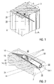
- FIG. 1 illustrates a section of a tunnel through rock 1, into which boreholes originate from a tunnel wall 2 3 are drilled.
- a seismic measuring device 30 (so-called seismic sensor rod) according to the invention with the anchoring device 10 (partially shown) and the sensor device 20, the details of which are described below.
- the anchoring device 10 is firmly connected by a binder with the surrounding rock 1.
- a binder z.
- B. a two-component epoxy adhesive 4 is used.
- the diameter a of the boreholes 2 is selected as a function of the maximum outside diameter and the length of the anchoring device 10, the drilling technology used, the rock material and its pressure. Typically, the diameter is a rd. 10 mm greater than the maximum diameter of the anchoring device 10, in order to ensure a good mixing of the binder in the borehole and at the same time to limit the binder consumption.
- the length b of the boreholes 3 is selected as a function of the length of the anchoring device 10, which is adapted to the composition of the loosening region of the tunnel wall 2 and the preferred type of shaft to be measured.
- the length of the anchoring device 10 is preferably in the range of 0.2 m to 4 m.
- the diameter of the anchoring device 10 is selected depending on the size and number of sensors used and is preferably in the range of 3 cm to 4 cm.
- the anchoring device 10 comprises, as a tubular casing part, the anchoring pipe 11, at the pipe end 15 of which the oblique-angled tip element 16 is provided.
- the anchoring tube 11 and the tip member 16 are secured against rotation with each other.
- Inside the anchoring tube 11 is located at the tube end 15, the receptacle 12 for the sensor device 20.
- a milled internal thread 14 (see FIG. 4) for positive and / or non-positive coupling of the sensor device 10 is provided at least in the region of the receptacle 12 as a tube threaded region.
- the sensor device 20 comprises the sensor part 21 with three seismic sensors 23 (eg geophones or accelerometers), which are arranged in a housing 22.
- the Gefone are glued firmly into the housing 22 with measuring axes perpendicular to each other by means of two-component epoxy resin adhesive.
- an external thread 25 for the positive and / or non-positive connection of the sensor device 20 is provided with the anchoring device 10.
- the sensor part 21 is fixedly connected to the rod-shaped carrier part 24.
- the support member 24 is made of glass fiber reinforced plastic. It includes a central channel 24.1, extend through the connecting lines from the sensors 23 to the protruding from the wall 2 of the rock 1 end of the sensor device 20.
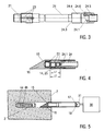
- FIG. 3 illustrates further details of the sensor device 20 according to the invention with the sensor part 21 and the carrier part 24, of which the areas near the ends 24.2, 24.3 are shown.
- the sensor part 21 is attached to the first end 24. 2 of the carrier part 24.
- second end 24.3 a screw 24.4 is provided, which extends axially to the support member 24.
- a plug 24.5 is glued with epoxy resin.
- the electrical connection lines extend from the sensors 23 through the channel 24.1 in the carrier part 24 to the plug 24.5.
- a check mark 24.6 is provided on the screw 24.4.
- the control mark 24.6 serves to check the orientation of the sensors 23 when the sensor device 20 is inserted into the anchoring device 10.
- the later position of the sensors is determined.
- Figure 4 illustrates the coupling of the sensor device 20 with the anchoring device 10 by the connection of the internal thread 12 of the receptacle 12 with the external thread 25 on the housing 22.
- the sensors 23 are arranged axially successively in the housing 22 with mutually perpendicular measuring axes.
- the measuring axis of the foremost sensor (axial sensor) runs parallel to the axis direction of the anchoring tube 11.
- the measuring axes of the other sensors are perpendicular to the axis direction of the anchoring tube 11.
- the inner and outer threads 14, 25 preferably extend over the region of the radially coupled sensors in order to improve their vibration coupling with the environment and signal transmission. Furthermore, in the coupling of the sensor part 20 with the receptacle 12, a biasing force is generated on the axially coupled geophone.
- the length L2 of the internal thread 14 of the anchoring device 10 is greater than the length L1 of the external thread 25 on the housing 22.
- the housing 22 or the front side of the axially coupled sensor at the pipe end 15 is preferably about a thread or 1 mm additional thread on the internal thread 25 available.
- the bias of the housing or the sensor in the thread and the adhesion to the anchoring tube is increased.
- FIG. 5 illustrates how the anchoring device 10 is inserted into the borehole 3.
- an epoxy resin adhesive 4 with the individual components 4a, 4b introduced.
- the individual components 4a, 4b are preferably separated from each other to avoid premature curing.
- the anchoring device 10 is pushed with the closed pipe end 15 into the borehole 3.
- an attached at the opposite, open end of the pipe rotary tool 30 can be used, which cooperates with an engagement member 17 at the open end.
- the anchoring device 10 is set during advancement in the borehole 3 in rotation.
- the individual components 4a, 4b are mixed by the rotation of the tip member 16, so that the curing of the epoxy resin adhesive begins.
- the anchoring device 10 is pushed forward or rotated until the anchoring tube 11 is completely arranged in the borehole 3.
- a position marker 18 At the open end of the anchoring tube 11 is a position marker 18, with which the orientation of the anchoring device 10 in the borehole 3 and in particular the orientation of the internal thread 14 can be observed.
- the open end of the tunnel wall 2 protrude to attach to an external thread (not shown), an anchor nut.
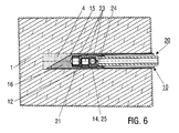
- the sensor device 20 is screwed into the anchoring device 10, as illustrated in FIG.
- the sensor part 21 with the sensors 23 is advanced with the support member 24 to the receptacle 12 and by screwing the inner and outer threads 14, 25 positively and / or non-positively coupled to the anchoring device 10.
Landscapes
- Physics & Mathematics (AREA)
- Life Sciences & Earth Sciences (AREA)
- Engineering & Computer Science (AREA)
- Acoustics & Sound (AREA)
- Environmental & Geological Engineering (AREA)
- Geology (AREA)
- Remote Sensing (AREA)
- General Life Sciences & Earth Sciences (AREA)
- General Physics & Mathematics (AREA)
- Geophysics (AREA)
- Geophysics And Detection Of Objects (AREA)
- Measurement Of Mechanical Vibrations Or Ultrasonic Waves (AREA)
Applications Claiming Priority (1)
| Application Number | Priority Date | Filing Date | Title |
|---|---|---|---|
| DE200610007474 DE102006007474B4 (de) | 2006-02-17 | 2006-02-17 | Verankerungseinrichtung für eine Sensoreinrichtung zur Erfassung von seismischen Signalen in geologischen Strukturen oder Bauwerken |
Publications (2)
| Publication Number | Publication Date |
|---|---|
| EP1821119A2 true EP1821119A2 (fr) | 2007-08-22 |
| EP1821119A3 EP1821119A3 (fr) | 2010-06-23 |
Family
ID=38055482
Family Applications (1)
| Application Number | Title | Priority Date | Filing Date |
|---|---|---|---|
| EP07003162A Withdrawn EP1821119A3 (fr) | 2006-02-17 | 2007-02-14 | Dispositif d'ancrage et dispositif de détection pour un appareil de mesure sismique |
Country Status (2)
| Country | Link |
|---|---|
| EP (1) | EP1821119A3 (fr) |
| DE (1) | DE102006007474B4 (fr) |
Cited By (2)
| Publication number | Priority date | Publication date | Assignee | Title |
|---|---|---|---|---|
| CN115012904A (zh) * | 2022-06-16 | 2022-09-06 | 中煤科工集团重庆研究院有限公司 | 一种拱形弹片式地震波传感器钻孔耦合装置 |
| CN118818593A (zh) * | 2024-06-26 | 2024-10-22 | 中国电建集团成都勘测设计研究院有限公司 | 一种隧洞tbm掘进地震超前预报接收装置 |
Families Citing this family (1)
| Publication number | Priority date | Publication date | Assignee | Title |
|---|---|---|---|---|
| CN110469354A (zh) * | 2019-08-30 | 2019-11-19 | 东北大学 | 一种用于围岩微震监测的抗拉拔锚杆 |
Family Cites Families (6)
| Publication number | Priority date | Publication date | Assignee | Title |
|---|---|---|---|---|
| CH689191A5 (de) * | 1994-02-22 | 1998-11-30 | Amberg Messtechnik Ag 7320 Sar | Aufnehmervorrichtung zur Aufnahme von seismischen Signalen und Verwendung dieser Aufnehmervorrichtung. |
| EP0753161B1 (fr) * | 1994-03-30 | 2000-05-24 | Thomson Marconi Sonar Limited | Capteur acoustique |
| DE19852455C2 (de) * | 1998-11-13 | 2003-12-24 | Geoforschungszentrum Potsdam | Verankerungseinrichtung mit seismischem Sensor |
| US6294727B1 (en) * | 1999-02-19 | 2001-09-25 | Syntron, Inc. | Takeout anchor and protective cover |
| US6307808B1 (en) * | 2000-02-01 | 2001-10-23 | Lesley J. Schmidt | Methods and apparatuses for seismic prospecting |
| DE10231780A1 (de) * | 2002-07-13 | 2004-01-29 | Ludger Boese | Vorrichtung zur Durchführung seismischer Untersuchungen |
-
2006
- 2006-02-17 DE DE200610007474 patent/DE102006007474B4/de not_active Expired - Fee Related
-
2007
- 2007-02-14 EP EP07003162A patent/EP1821119A3/fr not_active Withdrawn
Non-Patent Citations (1)
| Title |
|---|
| GUSTAV ADLHOCH: "Interview - KEM vor ort", 22 March 2005 (2005-03-22), XP055247841, Retrieved from the Internet <URL:https://kem.industrie.de/allgemein/interview-kem-vor-ort-10/> [retrieved on 20160205] * |
Cited By (2)
| Publication number | Priority date | Publication date | Assignee | Title |
|---|---|---|---|---|
| CN115012904A (zh) * | 2022-06-16 | 2022-09-06 | 中煤科工集团重庆研究院有限公司 | 一种拱形弹片式地震波传感器钻孔耦合装置 |
| CN118818593A (zh) * | 2024-06-26 | 2024-10-22 | 中国电建集团成都勘测设计研究院有限公司 | 一种隧洞tbm掘进地震超前预报接收装置 |
Also Published As
| Publication number | Publication date |
|---|---|
| DE102006007474A1 (de) | 2007-08-30 |
| EP1821119A3 (fr) | 2010-06-23 |
| DE102006007474B4 (de) | 2008-07-31 |
Similar Documents
| Publication | Publication Date | Title |
|---|---|---|
| EP2257690B1 (fr) | Cheville autoforeuse protégée contre la corrosion, et bloc d'éléments de cheville, et leur procédé de fabrication | |
| DE102014104552A1 (de) | Bohrkopf und Vorrichtung zum Herstellen einer Bohrung im Erdreich | |
| EP3507509B1 (fr) | Capteur de distance sur un bec d'ancre | |
| EP1001134B1 (fr) | Dispositif d'ancrage avec un capteur sismique | |
| DE10336043A1 (de) | Verbundanker | |
| DE2611676A1 (de) | Verfahren und vorrichtung zum niederbringen von erdbohrungen fuer erdanker | |
| DE4204533C2 (de) | Injektionsbohranker | |
| WO2013053352A1 (fr) | Ensemble de fixation pourvu d'une vis à double fonction | |
| EP2112384B1 (fr) | Cheville dotée d'un élément de fixation et d'une douille | |
| DE102006007474B4 (de) | Verankerungseinrichtung für eine Sensoreinrichtung zur Erfassung von seismischen Signalen in geologischen Strukturen oder Bauwerken | |
| EP4183974B1 (fr) | Système de tige creuse assisté par capteur | |
| AT501875B1 (de) | Verfahren und vorrichtung zum bohren, insbesondere schlag- oder drehschlagbohren eines lochs in boden- oder gesteinsmaterial | |
| DE2611677B2 (de) | Vorrichtung zum Einbringen von Rohren | |
| DE9004176U1 (de) | Injektionsbohranker mit Transportschnecke | |
| AT413231B (de) | Verfahren und vorrichtung zum bohren von löchern in boden- oder gesteinsmaterial | |
| EP2146050A2 (fr) | Procédé de fixation d'un élément de fixation auto-perceur pouvant être ancré chimiquement | |
| DE102005015494B4 (de) | Bajonettkupplung | |
| DE4032682C2 (de) | Gebirgsanker | |
| AT394449B (de) | Vorrichtung zur bestimmung von zug- und/oder druckspannungen sowie verfahren zum setzen derselben | |
| DE102007000360A1 (de) | Chemisch verankerbares Befestigungselement | |
| DE10231779B3 (de) | Vorrichtung zur Positionierung eines mit wenigstens einem seismischen Sensor versehenen Messkopfes | |
| AT505335B1 (de) | Vorrichtung zum herstellen eines bohrloches in gesteinsmaterial | |
| DE19842173A1 (de) | Befestigungselement mit selbstfurchender Schraubverbindung | |
| DE2624393C3 (de) | Verfahren und Vorrichtungen zur orientierten Entnahme von Bohrkernen | |
| EP2896750B1 (fr) | Dispositif et procédé d'ancrage d'une construction |
Legal Events
| Date | Code | Title | Description |
|---|---|---|---|
| PUAI | Public reference made under article 153(3) epc to a published international application that has entered the european phase |
Free format text: ORIGINAL CODE: 0009012 |
|
| AK | Designated contracting states |
Kind code of ref document: A2 Designated state(s): AT BE BG CH CY CZ DE DK EE ES FI FR GB GR HU IE IS IT LI LT LU LV MC NL PL PT RO SE SI SK TR |
|
| AX | Request for extension of the european patent |
Extension state: AL BA HR MK YU |
|
| RAP1 | Party data changed (applicant data changed or rights of an application transferred) |
Owner name: HELMHOLTZ-ZENTRUM POTSDAM DEUTSCHES GEOFORSCHUNGSZ |
|
| PUAL | Search report despatched |
Free format text: ORIGINAL CODE: 0009013 |
|
| AK | Designated contracting states |
Kind code of ref document: A3 Designated state(s): AT BE BG CH CY CZ DE DK EE ES FI FR GB GR HU IE IS IT LI LT LU LV MC NL PL PT RO SE SI SK TR |
|
| AX | Request for extension of the european patent |
Extension state: AL BA HR MK RS |
|
| 17P | Request for examination filed |
Effective date: 20101210 |
|
| AKX | Designation fees paid |
Designated state(s): AT CH FR IT LI |
|
| REG | Reference to a national code |
Ref country code: DE Ref legal event code: R108 Effective date: 20110201 Ref country code: DE Ref legal event code: 8566 |
|
| 17Q | First examination report despatched |
Effective date: 20160210 |
|
| GRAP | Despatch of communication of intention to grant a patent |
Free format text: ORIGINAL CODE: EPIDOSNIGR1 |
|
| STAA | Information on the status of an ep patent application or granted ep patent |
Free format text: STATUS: GRANT OF PATENT IS INTENDED |
|
| INTG | Intention to grant announced |
Effective date: 20180323 |
|
| STAA | Information on the status of an ep patent application or granted ep patent |
Free format text: STATUS: THE APPLICATION IS DEEMED TO BE WITHDRAWN |
|
| 18D | Application deemed to be withdrawn |
Effective date: 20180803 |