EP1821120A2 - Dispositif optoélectronique et son procédé de fonctionnement - Google Patents
Dispositif optoélectronique et son procédé de fonctionnement Download PDFInfo
- Publication number
- EP1821120A2 EP1821120A2 EP07003359A EP07003359A EP1821120A2 EP 1821120 A2 EP1821120 A2 EP 1821120A2 EP 07003359 A EP07003359 A EP 07003359A EP 07003359 A EP07003359 A EP 07003359A EP 1821120 A2 EP1821120 A2 EP 1821120A2
- Authority
- EP
- European Patent Office
- Prior art keywords
- signal distribution
- subpixels
- received signal
- object detection
- distance
- Prior art date
- Legal status (The legal status is an assumption and is not a legal conclusion. Google has not performed a legal analysis and makes no representation as to the accuracy of the status listed.)
- Granted
Links
Images


Classifications
-
- G—PHYSICS
- G01—MEASURING; TESTING
- G01V—GEOPHYSICS; GRAVITATIONAL MEASUREMENTS; DETECTING MASSES OR OBJECTS; TAGS
- G01V8/00—Prospecting or detecting by optical means
- G01V8/10—Detecting, e.g. by using light barriers
- G01V8/20—Detecting, e.g. by using light barriers using multiple transmitters or receivers
-
- G—PHYSICS
- G01—MEASURING; TESTING
- G01C—MEASURING DISTANCES, LEVELS OR BEARINGS; SURVEYING; NAVIGATION; GYROSCOPIC INSTRUMENTS; PHOTOGRAMMETRY OR VIDEOGRAMMETRY
- G01C3/00—Measuring distances in line of sight; Optical rangefinders
- G01C3/02—Details
- G01C3/06—Use of electric means to obtain final indication
- G01C3/08—Use of electric radiation detectors
- G01C3/085—Use of electric radiation detectors with electronic parallax measurement
-
- G—PHYSICS
- G01—MEASURING; TESTING
- G01S—RADIO DIRECTION-FINDING; RADIO NAVIGATION; DETERMINING DISTANCE OR VELOCITY BY USE OF RADIO WAVES; LOCATING OR PRESENCE-DETECTING BY USE OF THE REFLECTION OR RERADIATION OF RADIO WAVES; ANALOGOUS ARRANGEMENTS USING OTHER WAVES
- G01S17/00—Systems using the reflection or reradiation of electromagnetic waves other than radio waves, e.g. lidar systems
- G01S17/02—Systems using the reflection of electromagnetic waves other than radio waves
- G01S17/06—Systems determining position data of a target
- G01S17/46—Indirect determination of position data
- G01S17/48—Active triangulation systems, i.e. using the transmission and reflection of electromagnetic waves other than radio waves
-
- G—PHYSICS
- G01—MEASURING; TESTING
- G01S—RADIO DIRECTION-FINDING; RADIO NAVIGATION; DETERMINING DISTANCE OR VELOCITY BY USE OF RADIO WAVES; LOCATING OR PRESENCE-DETECTING BY USE OF THE REFLECTION OR RERADIATION OF RADIO WAVES; ANALOGOUS ARRANGEMENTS USING OTHER WAVES
- G01S7/00—Details of systems according to groups G01S13/00, G01S15/00, G01S17/00
- G01S7/48—Details of systems according to groups G01S13/00, G01S15/00, G01S17/00 of systems according to group G01S17/00
- G01S7/481—Constructional features, e.g. arrangements of optical elements
- G01S7/4816—Constructional features, e.g. arrangements of optical elements of receivers alone
Definitions
- the present invention relates to an opto-electronic device for detecting an object by means of a light scanner, are detected by a light source and backscattered by an object and / or reflected light beams are detected by the triangulation principle of a receiving device and an object detection signal is output.
- the present invention relates to methods for operating such a device.
- a triangulation light switch with switch output generates an item detection signal when an item is within a predetermined range.
- a distance measuring triangulation light sensor can measure the distance between the light sensor and an object and provide a distance proportional output signal.
- the light source which may additionally be provided with a transmission optics, emits an ideally parallel beam which, when hitting the surface of an object, generates a light spot which is emitted by the light source Object is scattered back.
- This light spot is imaged via a laterally offset to the light source receiver optics in a receiver plane, the image is usually blurred, since the receiver level is usually not in the image plane.
- the steels backscattered by the article pass through the receiver optics at different angles and thus also encounter different lateral positions in the receiver plane.
- the distance of the object from the light scanner can be determined by means of triangulation with knowledge of the distance between the receiver optics and the receiver plane and of the position and direction of the beam emitted by the light source.
- the receiver optics are formed by an infinitely small pinhole, as this is the only way to ensure that the distance is detected independently of interferences.
- a receiver optics is used with an aperture whose minimum size is determined by the limited sensitivity of the receiver and by the signal-to-noise ratio of the entire system.
- the measurement result can be falsified if only a part of the receiver optics is illuminated in an asymmetrical manner. This can be done, for example, by the light beam emitted by the light source striking a contrast boundary present in the surface of the object, the contrast boundary separating areas with very high and very low backscatter capability. This shifts the measured light spot center of gravity to the expected light spot centroid in the receiver plane undesirably.
- a light beam reflected by the object only partially illuminates the receiver optics, in contrast to a backscattered light beam. If the reflected beam does not strike the receiver optics in the area of the optical axis, the reflected beams produce a light spot whose position differs from the position of the light spot produced by the backscattered beams. Since the reflected rays generally have a higher intensity than the backscattered rays, depending on the angle of the object surface to the beam direction of the emitted light rays from the light source can lead to a misdetection.
- the object of the present invention is therefore to provide a device for more reliable detection of an object and method for operating such a device.
- the object of the invention is achieved by an optoelectronic device for detecting an object according to the principle of triangulation with a light source, a receiving arrangement for detecting light rays backscattered and / or reflected by an object and an evaluation unit, which is characterized in that the receiving arrangement a receiver optics for deflecting the light rays backscattered and / or reflected by the object, a microlens array connected downstream of the receiver optics and a pixel array consisting of photodetectors, wherein each microlens is assigned a macropixel having a plurality of subpixels, and the evaluation unit comprises a unit for determining the received signal distribution via which includes subpixels within a macro pixel.
- an object detection signal can not only be determined from the position of a light spot generated by the detected object on the receiver. Rather, it is possible to obtain a distance information from the received signal distribution within one or more macropixels. Namely, the microlens array can obtain the information for performing triangulation not only in the absolute position of a light spot image on the receiver, but also from the additional information existing in each illuminated macropixel about the angle of incidence of the receiving beams on the receiving device and / or about asymmetries in the illumination the receiver optics, as will be explained in more detail below.
- the device according to the invention provides options for avoiding and / or quantifying the artifacts described at the outset which may falsify the result of the object detection and, if necessary, for correcting the result.
- the pixel array may be line-shaped. This arrangement provides a cost effective solution if only lower detection accuracy or sensitivity is needed.
- the pixel array may be in the form of a two-dimensional array. With a two-dimensional array, it is also possible to detect asymmetries in a second lateral direction compared with a line-shaped pixel array.
- the pixel array may preferably be a CCD sensor, a CMOS sensor or an arrangement of PIN diodes.
- the light source is a laser or an LED.
- a laser usually no additional transmission optics need to be provided.
- lasers or LEDs are available which emit light in the infrared range, so that it is possible to realize light scanners that are largely insensitive to any visible stray light.
- the focal lengths and / or the apertures of the receiver optics and the microlenses are selected such that at least the light beams backscattered by an object located within a detection region which completely illuminate the receiver optics are deflectable by a plurality of adjacent microlenses and within each the macropixels assigned to these microlenses can be focused or deflected onto a subarea of the respective macropixel comprising, in particular, a plurality of individual subpixels.
- focus in the sense of this invention is to be understood in principle also a pure deflection of light rays without exact focus on a point.
- the focal lengths and / or the apertures are dimensioned such that a through the light source on the object generated light spot is imaged approximately only on a respective portion of the affected macropixel, which ideally comprises one to three subpixels, so that information about the angle of incidence of the receiving beams on the receiving device in the position of or by the focused receiving beams acted upon subpixel or in the Position of a characteristic of the received signal distribution is given within the affected macropixel.
- such a metapixel is always energized when light from an object located in the corresponding distance or distance range meets the receiving arrangement.
- a metapixel is also excited when only a part of the metapixel associated subpixel is applied, i. if e.g. the article does not have an ideal backscattering surface.
- metapixels are provided, to each of which different distance values and / or distance ranges are assigned.
- objects located in different areas can also be detected by the evaluation of the metapixels.
- the subpixels are permanently connected.
- the subpixels can be variably connected.
- the object of the invention is further achieved by a method for operating the device according to one of claims 1 to 9, which represents a first variant of the method and is characterized in that the object detection signal in response to the received signal distribution over the macropixels and / or in dependence on the Receive signal distribution over the subpixels of at least one macropixel and / or generated as a function of the received signal distribution over the metapixels.
- the invention it is thus possible to use for object detection both a signal distribution over the macropixels, which in principle corresponds to a conventional triangulation light scanner, as well as to consider the received signal distribution via the subpixels of a macropixel and / or the received signal distribution via the metapixels.
- the advantages are thus to evaluate the different received signal distributions as needed individually or in combination with each other.
- an object detection signal determined in dependence on the received signal distribution via the macropixels is corrected on the basis of the received signal distribution via the subpixels of at least one macropixel.
- the received signal distribution is determined via the macropixels and from this the distance of the object is determined.
- a determination of the received signal distribution takes place via the subpixels of one or more macro pixels, from which a distance value is likewise determined, if necessary by averaging over a plurality of distance values.
- the macro-pixel with the highest intensity can be taken into account exclusively or with a higher weighting. If both evaluations do not lead to the same distance value, the distance value determined from the received signal distribution via the macropixels can be replaced by the distance value determined from the received signal distribution via the subpixels of at least one macropixel, which in this case is then more likely to be more correct.
- an object detection signal determined in dependence on the received signal distribution via the macropixels is corrected on the basis of the received signal distribution via the metapixels.
- the received signal distribution is determined via the macropixels and from this the distance of the object is determined.
- a determination of the received signal distribution via the metapixels from which a further distance value is determined.
- the distance value determined from the received signal distribution via the macropixels can be replaced by the distance value determined from the received signal distribution via the metapixels, if both evaluations do not lead to the same distance value.
- an object detection signal based on the received signal distribution can first be determined via the macropixels and optionally corrected, taking into account the received signal distribution via the subpixels and / or the metapixels. In this way, an incorrect determination caused, for example, by uneven illumination of the receiver optics can be avoided by matching with the received signal distribution via the subpixels and / or the metapixels.
- the object detection signal is generated only as a function of the received signal distribution over a plurality of metapixels used for object detection.
- this method variant is thus on the determination of the received signal distribution over the macropixels and over the subpixels dispensed at least one macropixel and only takes into account the received signal distribution over the metapixels.
- the object detection signal is generated only as a function of the received signal distribution via the subpixels of the macropixels. In this method variant, therefore, the determination of the received signal distribution via the macropixels and via the metapixels is dispensed with and only the received signal distribution via the subpixels is taken into account.
- the object detection signal is preferably generated and / or corrected as a function of the position of a characteristic of the received signal distribution.
- the term "receive signal distribution" in the context of all embodiments of the invention generally also includes the pure determination of the position of the center of gravity or the maximum of the received signal within the metapixels, the macropixels or the subpixels of a macropixel.
- the object detection signal is generated as a binary output signal due to an object located within a predetermined detection range.
- the binary output signal is a function of the position of a characteristic of the received signal distribution over the metapixels.
- the received signal distribution is determined via the metapixels and subsequently based on the position of the characteristic of this distribution made a decision which of the two output states of the binary output signal is to be output.
- two mutually complementary distances and / or distance ranges can each be assigned to one of two metapixels, the then merely binary output signal assuming a state as a function of the respectively most heavily applied metapixel.
- a simple generation of the output signal with short switching times is possible.
- the object detection signal is generated as an analog and / or digital distance signal, which is a measure of the distance of the object from the receiving device and / or the light source and is a function of the position of a characteristic of the received signal distribution.
- This arrangement represents a measuring triangulation light scanner.
- the object of the invention is further achieved by a method for operating the device according to one of claims 1 to 9, which represents a second variant of the method and is characterized in that the received signals supplied by a macro pixel are used for object detection when the subpixels of the respective macropixel have a substantially symmetrical signal distribution, and that the received signals supplied by a macro pixel are not used or only after performing a correction step for object detection when the subpixels of the respective macropixel have a substantially asymmetric signal distribution.
- a symmetrical signal distribution is to be understood as meaning a symmetrical reception signal distribution with respect to an axis of symmetry the symmetry axis can run both centrally and off-center with respect to the respective macropixel.
- an asymmetry arising, for example, by detecting reflected light beams can be detected, since the subpixels within a macropixel only have a symmetrical signal distribution if the receiving arrangement or its aperture is illuminated substantially homogeneously, which then leads to illumination of a Area of the pixel array leads, which has at least the extent of a macro pixel.
- the signal distribution within a macropixel has an asymmetry, i. certain edge areas of a macropixel are e.g. have been better illuminated compared to other peripheral areas.
- the determination of a "valid" macropixel can also be effected by comparing the determined received signal distribution via the subpixels of a macropixel with a previously stored reference signal distribution via the subpixels of this macropixel, which adjusts at predetermined intervals.
- the reference signal distribution can both be calculated and determined during a teach-in process.
- An invalid macropixel is present if, when compared with the reference signal distribution assigned to this macropixel, a sufficiently large deviation, for example above a given threshold, is found.
- the object detection signal can be determined on the basis of a signal distribution over a plurality of used for object detection "valid" macropixels, wherein a signal of each "valid" macropixel is determined by summation over the subpixel.
- a signal distribution over the sum signals of these macropixels is determined.
- the object detection signal can be generated from the position of a characteristic of the signal distribution within the pixel array, the signal distribution being determined from a plurality of "valid" macro-pixels used for object detection. From the distance of the characteristic of the signal distribution to a Reference point, the distance of the object from the device according to the invention can be determined.
- the object detection signal is generated as a function of the position of the geometric center of gravity or of the maximum of the signal distribution.
- correction may be made e.g. by a corrected determination of the center of gravity of the signal distribution over the macropixels.
- a macropixel having an asymmetric signal distribution is weighted with a corrected location coordinate, the difference between the original and corrected location coordinates being proportional to the asymmetry-related shift in the center of gravity of the signal distribution over the subpixels of that macropixel.
- the proportionality factor can either be determined experimentally for each pixel or calculated from the geometrical relationships of the Lichttasteranordung. The determined values can be stored in a table and used in the operation of the light sensor for the calculation of the corrected location coordinates.
- the center of gravity p of the signal distribution over the macropixels is calculated as the sum over all sum signals S i of each macropixel multiplied by the corresponding macropixel coordinate x i (sum of the signals of all subpixels of a macropixel) divided by the sum over all sum signals S i , the sum signal S i is formed as a sum over the signals of all subpixels belonging to a macropixel i .
- the correction is done in the following way:
- the center of gravity q i of the signal distribution within a macropixel i is calculated in a corresponding manner.
- a displacement factor v i is determined, which can assume values between -1 and +1. In the case of symmetrical signal distribution in a macropixel, v i is equal to 0.
- a correction value DX i is determined which indicates by how many pixel positions the position of a light spot generated by reflected light beams is maximally different from the position of a light spot generated by backscattered light beams when both light beams emanate from the same location.
- the correction value DX i can be determined experimentally, for example, by first determining the position p i of the light spot generated by a backscattering object and then replacing the backscattering object by a reflecting object arranged at the same location. Its angular orientation is varied so that the reflected light rays pass through the receiver aperture in a peripheral region. The associated new position pu i of the center of gravity of the light spot is determined accordingly.
- the associated displacement factor v (pu) i is determined analogously to the determination of the displacement factor v i .
- the correction value DX i is calculated from the divided by v (pu) i pu difference between i and p i.
- the correction values DX i are tabulated for all macropixels i . Due to the asymmetrical imaging geometry of a triangulation light scanner, it makes sense to determine DX i separately for the one edge region and an edge region of the receiver aperture opposite thereto, ie for positive and negative signs of v i .
- a corrected pixel coordinate x' i is used, which is derived from x i by addition of the product from the correction value DX read from the table i and the correction factor v i .
- the object detection signal may be generated as a binary output signal due to an object located within a predetermined range, the output signal being a function of the position of a characteristic of the signal distribution within the pixel array. It is e.g. a certain signal state is output when the object is at a certain distance or within a predetermined distance to the light sensor. If no object is within the specified distance, the signal state complementary thereto is output.
- the object detection signal can be generated as an analog and / or digital distance signal on the basis of a detected object, wherein the size of the distance signal a Measure of the distance of the object from the receiving device and / or the light source and is a function of the position of a characteristic of the signal distribution within the pixel array.
- the object detection signal retains its last value immediately before this detection when recognizing at least one macropixel having a substantially asymmetrical signal distribution via the subpixels, so that in this case no updating of the object detection signal takes place. This ensures that a short-term detection of reflected light beams does not lead to a faulty object detection signal.
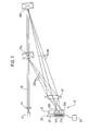
- Fig. 1 shows schematically a triangulation light 10, the individual components are not shown to scale for better understanding of the functioning and partially only partially.
- the components can be arranged separately or combined in a common housing not shown in the figure.
- a light source 12 emits divergent light beams, which are deflected by means of a transmitting optical system 14 to an approximately parallel beam 16.
- the resulting image spot illuminates approximately a first microlens 26a of the microlens array 24 which, in turn, directs the backscattered beams 20a onto a receiver 28, which is also arranged directly behind the microlens array 24 and is also shown only in sections.
- the receiver 28 consists of a pixel array which has a plurality of subpixels 30, wherein in each case three adjacent subpixels 30 are combined to form a macropixel 32a, 32b.
- the macropixel 32a is associated with the microlens 26a and can receive the beams deflected by it. Accordingly, the macropixel 32b is associated with the adjacent microlens 26b.
- the backscattered beams 20a generate in the subpixels 30 of the macro pixel 32a a signal whose height is indicated by the size of the hatched areas in the subpixels 30.
- the beam 16 emitted by the light source 12 strikes a second object 18b and generates backscattered beams 20b, shown in solid lines, which also strike the receiver optics 22.
- the receiver optics 22 due to the different spacing of the two objects 18a, 18b, they fall on the receiver optics 22 at a different angle and therefore on a second microlens 26b adjacent to the first microlens 26a. This deflects the backscattered beams 20b onto a second macropixel 32b adjacent to the first macropixel 32a.
- Both in backscatter by the first and by the second article 18a, 18b results due to the light-scattering properties the surfaces of the objects 18a, 18b, a symmetrical illumination of the subpixels 30 of the macropixels 32a and 32b, which is illustrated in FIG. 1 by the mutually equal sizes of the hatched areas of the respective subpixels 30.
- Fig. 2 corresponds substantially to that of Fig. 1, wherein at the location of the object 18b shown in Fig. 1, an object 18c is located, the surface of which not only backscatter the beam 16 but also reflects.
- the backscattered beams 20c shown as a solid line are deflected by the receiver optics 22 and the microlens 26b onto the macropixel 32b, resulting in a symmetrical illumination of the subpixels 30 of the macropixel 32b.
- the rays 36 reflected by the object 18c are shown in FIG. 2 as dashed lines and, in contrast to the backscattered rays 20c, assume a substantially flat object surface as a parallel beam whose diameter corresponds to that of the incident beam 16.
- the reflected beam 36 does not illuminate the receiver optics 22 over its entire area, the reflected beams are received only by a single subpixel of the macro pixel 32b.
- the resulting, in sum, correspondingly asymmetrical signal distribution is again shown by hatching in the subpixels 30 of the receiver 28.
- the reflected rays depend on the concrete surface properties of the article 18c usually have a higher beam density than the backscattered beams, since they are usually articulated in a much smaller solid angle, so that unrecognized disturbances would be particularly disadvantageous by such reflected rays.
- a sum signal for each of the macropixels 32 is now formed in the circumstances of FIG. 1, wherein all macropixels 32 are used for the evaluation, since their subpixels 30 each represent a symmetrical signal distribution within the macropixels 32.
- the resulting signal distribution over the macropixels 32 corresponds to a reduced image of the light spot produced by the beam 16 on the object 18a, 18b.
- the lateral position of the center of gravity of the signal distribution within the receiver 28 is a measure of the distance between the object 18 a or 18 b and the triangulation light sensor 10.
- a corresponding object detection signal is output by the evaluation unit.
- this can be a binary signal if an object is within a predetermined detection range.
- a digital or analog signal corresponding to the measured distance is output.
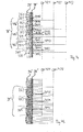
- FIGS. 3a and 3b schematically and partially show the receiving components of the triangulation light scanner, wherein the illustrated beam paths essentially relate to the position of the focal points of the receiver optics 22 'and the microlens array 24' and the number of subpixels per macropixel of those in Figures 1 and 2 Distinguish the beam paths shown, so that with this arrangement, a plurality of microlenses or macropixels can be illuminated.
- the rest of the construction corresponds to FIGS. 1 and 2.
- a reflected or scattered by a non-illustrated article receiving beam 38 strikes a receiver optics 22 'and is bundled by this on a only partially shown microlens array 24', which is arranged in contrast to the figures 1 and 2 within the focal length of the receiver optics 22 '.
- the microlenses 261 to 265 direct the receiving beam 38 to a receiver 28 ', which is likewise arranged only in sections, directly behind the microlens array 24'.
- the receiver 28 ' consists of a pixel array which has a plurality of subpixels 30', wherein in each case six adjacent subpixels 30 'are combined to form a macropixel 321 to 325.
- the macropixel 321 is assigned to the microlens 261 and can receive the beams deflected by it.
- the macropixels 322 to 325 are associated with the remaining microlenses 262 to 265, respectively.
- the receiving beam 38 according to FIG. 3 a is subdivided into three sub-beams 40 a, 40 b, 40 c, wherein only the beam paths of the beams delimiting them are shown.
- the center beams of the sub-beams 40a to 40c are indicated by arrows.
- the sub-beam 40 a strikes the microlens 262
- the sub-beam 40 b strikes the microlens 263
- the sub-beam 40 c strikes the microlens 264.
- the focal lengths of the receiver optics 22 'and of the microlens array 24' are selected so that the rays reaching a microlens approximately to a subpixel of the macropixel associated with this microlens are focused. It is understood that due to a predetermined by the optical components depth of focus range not a sharp image can be achieved on exactly one subpixel for all distances of a backscattering and / or reflective object.
- the change in the angle of incidence of the receiving beam 38, 38 ' which is caused by the change in the distance of the object, causes a shift in the reception of the macrophixel received signal distribution on the receiver 28', so that a triangulation by the determination of the position of a maximum and / or centroid of the received signal distribution with respect to the macropixels 321 to 325 is possible.
- the change in the angle of incidence also causes a change or shift in the received signal distribution within a macropixel assigned to a specific sub-beam.
- the macropixel 324 is considered, this is acted upon by the sub-beam 40c in FIG. 3a, with the microlens 264 essentially focusing the sub-beam 40c onto the second sub-pixel 3042.
- the partial bundle 40b ' is now directed to the macropixel 324 in FIG. 3b, with the associated microlens 264 in this case focusing the partial bundle 40b' onto the fifth micropixel 3045 of the macropixel 324.
- the change in the angle of incidence of the receiving beam 38, 38 'thus causes in the macropixel 324 a shift of the maximum of the received signal distribution by three subpixel units.
- a shift can be e.g. also for the macropixel 323 notice.
- the subpixel 3035 removed two subpixel units is applied in FIG. 3b.
- a distance between the object and the triangulation light scanner can not only be determined from the lateral position of the center of gravity of the received signal distribution via the macropixels, but also within a single macropixel, a distance determination from the received signal distribution via its subpixels is possible according to the triangulation principle ,
- each subpixel can be assigned a corresponding distance and stored in the evaluation unit.
- the assignment can take place both by means of corresponding reference measurements and by means of trigonometric calculations.
- FIGS. 3a and 3b An ideal backscattering article 18a, 18b, as shown in Fig. 1, will always fully illuminate the receiver optics 22 ', so that all three Partial bundles 40a to c are detected. According to FIG. 3 a, the focus of the received signal distribution will lie on the macropixel 323.
- an exclusively exclusively reflecting object 18c will direct the small spot of light generated by the beam 16 only to a portion of the receiver optics 22 ', as shown in FIG.
- the beam 40c (FIG. 3a) impinges on the microlens array 24 'and therefore acts only on the macropixel 324, the remaining macropixels remain dark or at least significantly darker than the macropixel 324.
- a focus determination will thus now determine the macropixel 324 as the focus of the received signal distribution.
- the macropixel 324 corresponds to the center of gravity of the received signal distribution, which is generated at an angle of incidence according to FIG. 3b from a backscattering object located at a different distance.
- a triangulation which focuses exclusively on the focal points of the received signal distribution via the macropixels would thus erroneously associate the partial bundle 40c according to FIG. 3a with an angle of incidence according to FIG. 3b and therefore lead to an incorrect determination of the distance.
- the evaluation unit can recognize that due to the application of the subpixel 3042 in FIG. 3a, the reflective object 18c must be located in a distance assigned to this subpixel 3042. An object to be assigned to a position according to FIG. 3b would have had to act on subpixel 3045 instead of subpixel 3042.
- the distance determination thus takes place in that the first Emphasis of the received signal distribution over the macropixels is determined and the distance is then determined depending on the received signal distribution over the subpixels of that macropixel to which the center of gravity has previously been assigned.
- the method described above can be modified in such a way that the individual subpixels are accessed directly for determining the object detection signal without taking into account the received signal distribution via the macro pixels. Since each subpixel, which is exposed to light rays, a certain distance value can be assigned, and usually several subpixels are acted upon by a backscattering at a certain distance object at the same time, these subpixels can be summarized into a metapixel.
- FIG. 4a Such an interconnection for a measuring triangulation light scanner is shown schematically in FIG. 4a. It can be done both in the form of a fixed wiring and by a variable assignment, which can be realized for example by means of a switch arrangement, but also by a corresponding software coding.
- Subpixels 3015, 3024, 3033, 3042 and 3051 are associated with metapixel 421
- subpixels 3016, 3025, 3034, 3043 and 3052 are associated with the metapixel 422
- the subpixels 3026, 3035, 3044 and 3053 are interconnected to the metapixel 423, wherein the subpixels each connected to a common metapixel are assigned the same distance value.
- the representation of further metapixels and the associated interconnections was omitted for the sake of clarity.
- the beam 38 "acts here on the subpixels 3025, 3034 and 3043 associated with the metapixel 422. Thus, determining the receive signal distribution across the metapixels would determine that the metapixel focus is at the metapixel 422, so ultimately the distance associated with that metapixel is determined.
- each of these subbeams 40a "through 40c" will also produce a centroid of the received signal distribution over the metapixels at the metapixel 422.
- a reliable object detection signal can be generated by an object located in the distance range assigned to a metapixel, independently of its surface properties.
- the beam 38 " which incidentally supplies the same microlenses 261 to 263 and subpixels 3025, 3034 and 3043 as in FIG. 4a, generates a signal in the metapixel 425 and thus leads to an object detection signal" ON ".
- the arrangement described above ensures reliable and reliable object detection both in the case of a measuring and a switching triangulation light sensor, even if only a part of the receiver optics is illuminated.
Landscapes
- Physics & Mathematics (AREA)
- Engineering & Computer Science (AREA)
- Electromagnetism (AREA)
- General Physics & Mathematics (AREA)
- Radar, Positioning & Navigation (AREA)
- Remote Sensing (AREA)
- Computer Networks & Wireless Communication (AREA)
- Geophysics (AREA)
- General Life Sciences & Earth Sciences (AREA)
- Life Sciences & Earth Sciences (AREA)
- Measurement Of Optical Distance (AREA)
- Length Measuring Devices By Optical Means (AREA)
- Optical Radar Systems And Details Thereof (AREA)
Applications Claiming Priority (1)
| Application Number | Priority Date | Filing Date | Title |
|---|---|---|---|
| DE102006007764A DE102006007764A1 (de) | 2006-02-20 | 2006-02-20 | Optoelektronische Vorrichtung und Verfahren zu deren Betrieb |
Publications (3)
| Publication Number | Publication Date |
|---|---|
| EP1821120A2 true EP1821120A2 (fr) | 2007-08-22 |
| EP1821120A3 EP1821120A3 (fr) | 2007-12-19 |
| EP1821120B1 EP1821120B1 (fr) | 2014-01-22 |
Family
ID=38229827
Family Applications (1)
| Application Number | Title | Priority Date | Filing Date |
|---|---|---|---|
| EP07003359.2A Not-in-force EP1821120B1 (fr) | 2006-02-20 | 2007-02-16 | Dispositif optoélectronique et son procédé de fonctionnement |
Country Status (4)
| Country | Link |
|---|---|
| US (1) | US7656541B2 (fr) |
| EP (1) | EP1821120B1 (fr) |
| JP (1) | JP2007225613A (fr) |
| DE (1) | DE102006007764A1 (fr) |
Cited By (3)
| Publication number | Priority date | Publication date | Assignee | Title |
|---|---|---|---|---|
| CN102445713A (zh) * | 2010-10-12 | 2012-05-09 | 西克股份公司 | 光电传感器 |
| EP3051312A1 (fr) * | 2015-02-02 | 2016-08-03 | Sick Ag | Capteur photoélectrique trigonométrique |
| CN113483682A (zh) * | 2021-06-16 | 2021-10-08 | 苏州赛腾精密电子股份有限公司 | 一种基于机器视觉的缝隙测量方法及系统 |
Families Citing this family (27)
| Publication number | Priority date | Publication date | Assignee | Title |
|---|---|---|---|---|
| DE102007004632A1 (de) | 2007-01-30 | 2008-07-31 | Sick Ag | Verfahren zur Erfassung eines Gegenstands und optoelektronische Vorrichtung |
| EP2136223A1 (fr) | 2008-06-17 | 2009-12-23 | Sick Ag | Procédé et dispositif destinés à la saisie d'un objet |
| CN102313882B (zh) * | 2011-07-22 | 2015-07-29 | 江苏徕兹光电科技有限公司 | 激光测距仪的光学系统结构 |
| EP2629050B2 (fr) | 2012-02-16 | 2017-02-15 | Sick AG | Capteur de triangulation |
| DE102013205801B4 (de) * | 2013-04-02 | 2016-11-10 | Sick Ag | Triangulationslichttaster |
| US9797716B2 (en) * | 2015-01-09 | 2017-10-24 | Ricoh Company, Ltd. | Estimating surface properties using a plenoptic camera |
| DE102015109775B3 (de) | 2015-06-18 | 2016-09-22 | RobArt GmbH | Optischer Triangulationssensor zur Entfernungsmessung |
| US10694169B1 (en) | 2015-08-14 | 2020-06-23 | Apple Inc. | Depth mapping with polarization and focus pixels |
| DE102015114883A1 (de) | 2015-09-04 | 2017-03-09 | RobArt GmbH | Identifizierung und Lokalisierung einer Basisstation eines autonomen mobilen Roboters |
| DE102015119501A1 (de) | 2015-11-11 | 2017-05-11 | RobArt GmbH | Unterteilung von Karten für die Roboternavigation |
| DE102015119865B4 (de) | 2015-11-17 | 2023-12-21 | RobArt GmbH | Robotergestützte Bearbeitung einer Oberfläche mittels eines Roboters |
| DE102015121666B3 (de) | 2015-12-11 | 2017-05-24 | RobArt GmbH | Fernsteuerung eines mobilen, autonomen Roboters |
| DE102016102644A1 (de) | 2016-02-15 | 2017-08-17 | RobArt GmbH | Verfahren zur Steuerung eines autonomen mobilen Roboters |
| US12140965B2 (en) | 2016-08-05 | 2024-11-12 | Rotrade Asset Management Gmbh | Method for controlling an autonomous mobile robot |
| CN107966863B (zh) * | 2016-10-19 | 2020-08-07 | 京东方科技集团股份有限公司 | 一种显示基板及其制作方法、显示面板、显示装置 |
| US11860292B2 (en) | 2016-11-17 | 2024-01-02 | Trinamix Gmbh | Detector and methods for authenticating at least one object |
| WO2018091640A2 (fr) * | 2016-11-17 | 2018-05-24 | Trinamix Gmbh | Détecteur pouvant détecter optiquement au moins un objet |
| US11709489B2 (en) | 2017-03-02 | 2023-07-25 | RobArt GmbH | Method for controlling an autonomous, mobile robot |
| US11719818B2 (en) | 2017-03-16 | 2023-08-08 | Trinamix Gmbh | Detector for optically detecting at least one object |
| DE102017109219A1 (de) | 2017-04-28 | 2018-10-31 | RobArt GmbH | Verfahren für die Roboternavigation |
| US10714520B1 (en) * | 2017-08-04 | 2020-07-14 | Facebook Technologies, Llc | Manufacturing an on-chip microlens array |
| EP3676630B1 (fr) | 2017-08-28 | 2022-11-30 | trinamiX GmbH | Télémètre pour déterminer au moins une information géométrique |
| US11668828B2 (en) | 2017-08-28 | 2023-06-06 | Trinamix Gmbh | Detector for determining a position of at least one object |
| CN107726993B (zh) * | 2017-10-30 | 2019-07-19 | 上海理工大学 | 基于光场图像宏像素最大梯度区域的颗粒深度测量方法 |
| DE102017127180A1 (de) | 2017-11-17 | 2019-05-23 | RobArt GmbH | Bodenbearbeitung mittels eines autonomen mobilen Roboters |
| DE102018102402A1 (de) * | 2018-02-02 | 2019-08-08 | Sick Ag | Triangulationslichttaster |
| DE102024136076A1 (de) * | 2024-12-04 | 2026-06-11 | Ifm Electronic Gmbh | Reflexions-Lichttaster mit Hintergrundausblendung und Verfahren zum Betreiben eines solchen |
Citations (1)
| Publication number | Priority date | Publication date | Assignee | Title |
|---|---|---|---|---|
| DE102004009484A1 (de) | 2003-10-16 | 2005-05-19 | Sensopart Industriesensorik Gmbh | Optischer Abstandshalter nach dem Triangulationsprinzip |
Family Cites Families (23)
| Publication number | Priority date | Publication date | Assignee | Title |
|---|---|---|---|---|
| US2216716A (en) * | 1938-07-01 | 1940-10-01 | Irving Kane | Distance measuring device |
| US4470681A (en) * | 1982-09-07 | 1984-09-11 | Polaroid Corporation | Method of and apparatus for detecting range using multiple range readings |
| DE3502634A1 (de) * | 1985-01-26 | 1985-06-20 | Deutsche Forschungs- und Versuchsanstalt für Luft- und Raumfahrt e.V., 5000 Köln | Optisch-elektronischer entfernungsmesser |
| JPH0616147B2 (ja) * | 1986-03-26 | 1994-03-02 | チノン株式会社 | カメラ |
| US4918622A (en) * | 1988-11-16 | 1990-04-17 | Eastman Kodak Company | Electronic graphic arts screener |
| ES2054406T3 (es) * | 1990-08-09 | 1994-08-01 | Hohner Elektrotechnik Kg | Dispositivo explorador optoelectronico. |
| US5076687A (en) * | 1990-08-28 | 1991-12-31 | Massachusetts Institute Of Technology | Optical ranging apparatus |
| US5497269A (en) * | 1992-06-25 | 1996-03-05 | Lockheed Missiles And Space Company, Inc. | Dispersive microlens |
| US5848305A (en) * | 1996-01-31 | 1998-12-08 | Canon Kabushiki Kaisha | Circulating shift register and distance measuring device |
| GB9708020D0 (en) * | 1996-09-07 | 1997-06-11 | Philips Electronics Nv | Image sensor |
| FR2761151B1 (fr) | 1997-03-21 | 1999-07-16 | Samuel Bucourt | Systeme optronique de mesure de distance sans contact d'une source lumineuse par analyse de la courbure du point d'onde issu de celle-ci |
| US6862098B1 (en) * | 1999-02-26 | 2005-03-01 | Anritsu Corporation | Apparatus and method for measuring displacement |
| DE19962701A1 (de) | 1999-12-23 | 2001-06-28 | Sick Ag | Verfahren zur Ermittlung der Position eines Lichtspots auf einer Fotodioden-Zeile |
| DE10117147A1 (de) * | 2001-04-05 | 2002-10-10 | Bodenseewerk Geraetetech | Dual-Mode-Suchkopf |
| DE10231178B4 (de) | 2002-07-10 | 2008-12-04 | Sick Ag | Optoelektronischer Sensor |
| JP4057937B2 (ja) * | 2003-03-25 | 2008-03-05 | 富士フイルム株式会社 | 露光装置 |
| DE10321888A1 (de) * | 2003-05-07 | 2004-12-02 | Universität Stuttgart | Messverfahren und Sensor, insbesondere zur optischen Abtastung bewegter Objekte |
| DE10335263B4 (de) * | 2003-08-01 | 2005-08-11 | Leuze Electronic Gmbh & Co Kg | Optischer Sensor |
| CN100451723C (zh) | 2003-11-12 | 2009-01-14 | 麦克罗尼克激光系统公司 | 用于修正slm戳图像缺陷的方法和器件 |
| WO2005047055A1 (fr) * | 2003-11-17 | 2005-05-26 | Intier Automotive Inc. | Boitier de mecanisme d'inclinaison a galet |
| DE102004003013B3 (de) * | 2004-01-20 | 2005-06-02 | Fraunhofer-Gesellschaft zur Förderung der angewandten Forschung e.V. | Bilderfassungssystem und dessen Verwendung |
| DE102004038940A1 (de) * | 2004-08-11 | 2006-02-23 | Leuze Electronic Gmbh & Co Kg | Optischer Sensor |
| WO2007025363A1 (fr) * | 2005-09-02 | 2007-03-08 | Neptec | Dispositif et procede de poursuite d'objet |
-
2006
- 2006-02-20 DE DE102006007764A patent/DE102006007764A1/de not_active Withdrawn
-
2007
- 2007-02-16 EP EP07003359.2A patent/EP1821120B1/fr not_active Not-in-force
- 2007-02-19 US US11/708,164 patent/US7656541B2/en active Active
- 2007-02-20 JP JP2007039939A patent/JP2007225613A/ja active Pending
Patent Citations (1)
| Publication number | Priority date | Publication date | Assignee | Title |
|---|---|---|---|---|
| DE102004009484A1 (de) | 2003-10-16 | 2005-05-19 | Sensopart Industriesensorik Gmbh | Optischer Abstandshalter nach dem Triangulationsprinzip |
Cited By (5)
| Publication number | Priority date | Publication date | Assignee | Title |
|---|---|---|---|---|
| CN102445713A (zh) * | 2010-10-12 | 2012-05-09 | 西克股份公司 | 光电传感器 |
| EP2461188A3 (fr) * | 2010-10-12 | 2012-06-27 | Sick Ag | Capteur optoélectronique |
| US8836957B2 (en) | 2010-10-12 | 2014-09-16 | Sick Ag | Optoelectronic sensor |
| EP3051312A1 (fr) * | 2015-02-02 | 2016-08-03 | Sick Ag | Capteur photoélectrique trigonométrique |
| CN113483682A (zh) * | 2021-06-16 | 2021-10-08 | 苏州赛腾精密电子股份有限公司 | 一种基于机器视觉的缝隙测量方法及系统 |
Also Published As
| Publication number | Publication date |
|---|---|
| DE102006007764A1 (de) | 2007-08-23 |
| JP2007225613A (ja) | 2007-09-06 |
| US7656541B2 (en) | 2010-02-02 |
| EP1821120A3 (fr) | 2007-12-19 |
| EP1821120B1 (fr) | 2014-01-22 |
| US20080130005A1 (en) | 2008-06-05 |
Similar Documents
| Publication | Publication Date | Title |
|---|---|---|
| EP1821120B1 (fr) | Dispositif optoélectronique et son procédé de fonctionnement | |
| EP1405037B1 (fr) | Dispositif de mesure optique de distance sur une plage de mesure etendue | |
| EP1953504B1 (fr) | Procédé de saisie optique d'un objet et dispositif optoélectronique | |
| DE4211875A1 (de) | Optischer Abstandssensor | |
| DE102017211735B4 (de) | Laserbearbeitungsvorrichtung und Laserbearbeitungssystem | |
| EP2629050B1 (fr) | Capteur de triangulation | |
| EP4310443B1 (fr) | Palpeur optique de triangulation | |
| EP1211480A2 (fr) | Appareil de mesure électro-optique pour déterminer la position relative d'objets ou de leurs superficies | |
| EP3607348B1 (fr) | Dispositif lidar et procédé pour le balayage d'un angle de balayage et l'évaluation d'un détecteur | |
| EP2479534B1 (fr) | Capteur optoelectrique | |
| DE102018219481A1 (de) | Baugruppe für einen LiDAR-Sensor und LiDAR-Sensor | |
| EP2767797A1 (fr) | Interféromètre ä faible cohérence et procédé de mesure optique à résolution spatiale du profil de surface d'un objet | |
| EP3051312B1 (fr) | Capteur photoelectrique trigonometrique | |
| DE102022129828B4 (de) | Optoelektronischer sensor | |
| DE102022129827B3 (de) | Optoelektronischer sensor | |
| EP3751256B1 (fr) | Système de capteur optoélectronique permettant de détecter des objets dans une zone de surveillance | |
| EP2963444B1 (fr) | Capteur et procédé de détection à un endroit précis d'un objet transporté dans une direction de transport, par rapport à un capteur | |
| DE102011051626B4 (de) | Optischer Sensor und Verfahren zur Durchführung von Distanzmessungen mittels eines optischen Sensors | |
| DE3407210C2 (de) | Photoelektrischer Schalter | |
| DE202022106339U1 (de) | Optoelektronischer Sensor | |
| DE202022106338U1 (de) | Optoelektronischer Sensor | |
| DE102013205801B4 (de) | Triangulationslichttaster | |
| DE102024125752A1 (de) | Verfahren zur Ermittlung wenigstens eines Auslöseschwellenwertes für wenigstens einen Empfangskanal einer optischen Detektionsvorrichtung | |
| DE102013001359B4 (de) | Lasertriangulationsvorrichtung und -verfahren mit Bildzeichenerkennung | |
| DE102024128982A1 (de) | Reflexions-Lichttaster |
Legal Events
| Date | Code | Title | Description |
|---|---|---|---|
| PUAI | Public reference made under article 153(3) epc to a published international application that has entered the european phase |
Free format text: ORIGINAL CODE: 0009012 |
|
| AK | Designated contracting states |
Kind code of ref document: A2 Designated state(s): AT BE BG CH CY CZ DE DK EE ES FI FR GB GR HU IE IS IT LI LT LU LV MC NL PL PT RO SE SI SK TR |
|
| AX | Request for extension of the european patent |
Extension state: AL BA HR MK YU |
|
| PUAL | Search report despatched |
Free format text: ORIGINAL CODE: 0009013 |
|
| AK | Designated contracting states |
Kind code of ref document: A3 Designated state(s): AT BE BG CH CY CZ DE DK EE ES FI FR GB GR HU IE IS IT LI LT LU LV MC NL PL PT RO SE SI SK TR |
|
| AX | Request for extension of the european patent |
Extension state: AL BA HR MK YU |
|
| RIC1 | Information provided on ipc code assigned before grant |
Ipc: G01S 17/48 20060101ALI20071109BHEP Ipc: G01C 3/08 20060101ALI20071109BHEP Ipc: G01V 8/20 20060101AFI20070716BHEP |
|
| 17P | Request for examination filed |
Effective date: 20071217 |
|
| AKX | Designation fees paid |
Designated state(s): AT BE BG CH CY CZ DE DK EE ES FI FR GB GR HU IE IS IT LI LT LU LV MC NL PL PT RO SE SI SK TR |
|
| 17Q | First examination report despatched |
Effective date: 20090327 |
|
| GRAP | Despatch of communication of intention to grant a patent |
Free format text: ORIGINAL CODE: EPIDOSNIGR1 |
|
| INTG | Intention to grant announced |
Effective date: 20130814 |
|
| GRAS | Grant fee paid |
Free format text: ORIGINAL CODE: EPIDOSNIGR3 |
|
| GRAA | (expected) grant |
Free format text: ORIGINAL CODE: 0009210 |
|
| AK | Designated contracting states |
Kind code of ref document: B1 Designated state(s): AT BE BG CH CY CZ DE DK EE ES FI FR GB GR HU IE IS IT LI LT LU LV MC NL PL PT RO SE SI SK TR |
|
| REG | Reference to a national code |
Ref country code: GB Ref legal event code: FG4D Free format text: NOT ENGLISH |
|
| REG | Reference to a national code |
Ref country code: CH Ref legal event code: EP |
|
| REG | Reference to a national code |
Ref country code: AT Ref legal event code: REF Ref document number: 651047 Country of ref document: AT Kind code of ref document: T Effective date: 20140215 |
|
| REG | Reference to a national code |
Ref country code: IE Ref legal event code: FG4D Free format text: LANGUAGE OF EP DOCUMENT: GERMAN |
|
| REG | Reference to a national code |
Ref country code: DE Ref legal event code: R096 Ref document number: 502007012717 Country of ref document: DE Effective date: 20140306 |
|
| REG | Reference to a national code |
Ref country code: NL Ref legal event code: VDEP Effective date: 20140122 |
|
| REG | Reference to a national code |
Ref country code: LT Ref legal event code: MG4D |
|
| PG25 | Lapsed in a contracting state [announced via postgrant information from national office to epo] |
Ref country code: LT Free format text: LAPSE BECAUSE OF FAILURE TO SUBMIT A TRANSLATION OF THE DESCRIPTION OR TO PAY THE FEE WITHIN THE PRESCRIBED TIME-LIMIT Effective date: 20140122 Ref country code: IS Free format text: LAPSE BECAUSE OF FAILURE TO SUBMIT A TRANSLATION OF THE DESCRIPTION OR TO PAY THE FEE WITHIN THE PRESCRIBED TIME-LIMIT Effective date: 20140522 |
|
| PG25 | Lapsed in a contracting state [announced via postgrant information from national office to epo] |
Ref country code: CY Free format text: LAPSE BECAUSE OF FAILURE TO SUBMIT A TRANSLATION OF THE DESCRIPTION OR TO PAY THE FEE WITHIN THE PRESCRIBED TIME-LIMIT Effective date: 20140122 Ref country code: PT Free format text: LAPSE BECAUSE OF FAILURE TO SUBMIT A TRANSLATION OF THE DESCRIPTION OR TO PAY THE FEE WITHIN THE PRESCRIBED TIME-LIMIT Effective date: 20140522 Ref country code: ES Free format text: LAPSE BECAUSE OF FAILURE TO SUBMIT A TRANSLATION OF THE DESCRIPTION OR TO PAY THE FEE WITHIN THE PRESCRIBED TIME-LIMIT Effective date: 20140122 Ref country code: FI Free format text: LAPSE BECAUSE OF FAILURE TO SUBMIT A TRANSLATION OF THE DESCRIPTION OR TO PAY THE FEE WITHIN THE PRESCRIBED TIME-LIMIT Effective date: 20140122 Ref country code: SE Free format text: LAPSE BECAUSE OF FAILURE TO SUBMIT A TRANSLATION OF THE DESCRIPTION OR TO PAY THE FEE WITHIN THE PRESCRIBED TIME-LIMIT Effective date: 20140122 Ref country code: NL Free format text: LAPSE BECAUSE OF FAILURE TO SUBMIT A TRANSLATION OF THE DESCRIPTION OR TO PAY THE FEE WITHIN THE PRESCRIBED TIME-LIMIT Effective date: 20140122 |
|
| BERE | Be: lapsed |
Owner name: SICK A.G. Effective date: 20140228 |
|
| PG25 | Lapsed in a contracting state [announced via postgrant information from national office to epo] |
Ref country code: LV Free format text: LAPSE BECAUSE OF FAILURE TO SUBMIT A TRANSLATION OF THE DESCRIPTION OR TO PAY THE FEE WITHIN THE PRESCRIBED TIME-LIMIT Effective date: 20140122 |
|
| REG | Reference to a national code |
Ref country code: DE Ref legal event code: R097 Ref document number: 502007012717 Country of ref document: DE |
|
| PG25 | Lapsed in a contracting state [announced via postgrant information from national office to epo] |
Ref country code: EE Free format text: LAPSE BECAUSE OF FAILURE TO SUBMIT A TRANSLATION OF THE DESCRIPTION OR TO PAY THE FEE WITHIN THE PRESCRIBED TIME-LIMIT Effective date: 20140122 Ref country code: RO Free format text: LAPSE BECAUSE OF FAILURE TO SUBMIT A TRANSLATION OF THE DESCRIPTION OR TO PAY THE FEE WITHIN THE PRESCRIBED TIME-LIMIT Effective date: 20140122 Ref country code: DK Free format text: LAPSE BECAUSE OF FAILURE TO SUBMIT A TRANSLATION OF THE DESCRIPTION OR TO PAY THE FEE WITHIN THE PRESCRIBED TIME-LIMIT Effective date: 20140122 Ref country code: MC Free format text: LAPSE BECAUSE OF FAILURE TO SUBMIT A TRANSLATION OF THE DESCRIPTION OR TO PAY THE FEE WITHIN THE PRESCRIBED TIME-LIMIT Effective date: 20140122 Ref country code: CZ Free format text: LAPSE BECAUSE OF FAILURE TO SUBMIT A TRANSLATION OF THE DESCRIPTION OR TO PAY THE FEE WITHIN THE PRESCRIBED TIME-LIMIT Effective date: 20140122 |
|
| PG25 | Lapsed in a contracting state [announced via postgrant information from national office to epo] |
Ref country code: SK Free format text: LAPSE BECAUSE OF FAILURE TO SUBMIT A TRANSLATION OF THE DESCRIPTION OR TO PAY THE FEE WITHIN THE PRESCRIBED TIME-LIMIT Effective date: 20140122 Ref country code: PL Free format text: LAPSE BECAUSE OF FAILURE TO SUBMIT A TRANSLATION OF THE DESCRIPTION OR TO PAY THE FEE WITHIN THE PRESCRIBED TIME-LIMIT Effective date: 20140122 |
|
| PLBE | No opposition filed within time limit |
Free format text: ORIGINAL CODE: 0009261 |
|
| STAA | Information on the status of an ep patent application or granted ep patent |
Free format text: STATUS: NO OPPOSITION FILED WITHIN TIME LIMIT |
|
| REG | Reference to a national code |
Ref country code: IE Ref legal event code: MM4A |
|
| GBPC | Gb: european patent ceased through non-payment of renewal fee |
Effective date: 20140422 |
|
| 26N | No opposition filed |
Effective date: 20141023 |
|
| PG25 | Lapsed in a contracting state [announced via postgrant information from national office to epo] |
Ref country code: IE Free format text: LAPSE BECAUSE OF NON-PAYMENT OF DUE FEES Effective date: 20140216 Ref country code: BE Free format text: LAPSE BECAUSE OF NON-PAYMENT OF DUE FEES Effective date: 20140228 Ref country code: GB Free format text: LAPSE BECAUSE OF NON-PAYMENT OF DUE FEES Effective date: 20140422 |
|
| REG | Reference to a national code |
Ref country code: DE Ref legal event code: R097 Ref document number: 502007012717 Country of ref document: DE Effective date: 20141023 |
|
| PG25 | Lapsed in a contracting state [announced via postgrant information from national office to epo] |
Ref country code: SI Free format text: LAPSE BECAUSE OF FAILURE TO SUBMIT A TRANSLATION OF THE DESCRIPTION OR TO PAY THE FEE WITHIN THE PRESCRIBED TIME-LIMIT Effective date: 20140122 |
|
| REG | Reference to a national code |
Ref country code: FR Ref legal event code: PLFP Year of fee payment: 10 |
|
| PG25 | Lapsed in a contracting state [announced via postgrant information from national office to epo] |
Ref country code: BG Free format text: LAPSE BECAUSE OF FAILURE TO SUBMIT A TRANSLATION OF THE DESCRIPTION OR TO PAY THE FEE WITHIN THE PRESCRIBED TIME-LIMIT Effective date: 20140122 |
|
| PG25 | Lapsed in a contracting state [announced via postgrant information from national office to epo] |
Ref country code: GR Free format text: LAPSE BECAUSE OF FAILURE TO SUBMIT A TRANSLATION OF THE DESCRIPTION OR TO PAY THE FEE WITHIN THE PRESCRIBED TIME-LIMIT Effective date: 20140423 |
|
| PG25 | Lapsed in a contracting state [announced via postgrant information from national office to epo] |
Ref country code: LU Free format text: LAPSE BECAUSE OF NON-PAYMENT OF DUE FEES Effective date: 20140216 Ref country code: HU Free format text: LAPSE BECAUSE OF FAILURE TO SUBMIT A TRANSLATION OF THE DESCRIPTION OR TO PAY THE FEE WITHIN THE PRESCRIBED TIME-LIMIT; INVALID AB INITIO Effective date: 20070216 Ref country code: TR Free format text: LAPSE BECAUSE OF FAILURE TO SUBMIT A TRANSLATION OF THE DESCRIPTION OR TO PAY THE FEE WITHIN THE PRESCRIBED TIME-LIMIT Effective date: 20140122 |
|
| REG | Reference to a national code |
Ref country code: FR Ref legal event code: PLFP Year of fee payment: 11 |
|
| PGFP | Annual fee paid to national office [announced via postgrant information from national office to epo] |
Ref country code: CH Payment date: 20170221 Year of fee payment: 11 |
|
| PGFP | Annual fee paid to national office [announced via postgrant information from national office to epo] |
Ref country code: AT Payment date: 20170217 Year of fee payment: 11 |
|
| REG | Reference to a national code |
Ref country code: FR Ref legal event code: PLFP Year of fee payment: 12 |
|
| REG | Reference to a national code |
Ref country code: CH Ref legal event code: PL |
|
| REG | Reference to a national code |
Ref country code: AT Ref legal event code: MM01 Ref document number: 651047 Country of ref document: AT Kind code of ref document: T Effective date: 20180216 |
|
| PG25 | Lapsed in a contracting state [announced via postgrant information from national office to epo] |
Ref country code: AT Free format text: LAPSE BECAUSE OF NON-PAYMENT OF DUE FEES Effective date: 20180216 Ref country code: CH Free format text: LAPSE BECAUSE OF NON-PAYMENT OF DUE FEES Effective date: 20180228 Ref country code: LI Free format text: LAPSE BECAUSE OF NON-PAYMENT OF DUE FEES Effective date: 20180228 |
|
| PGFP | Annual fee paid to national office [announced via postgrant information from national office to epo] |
Ref country code: IT Payment date: 20190222 Year of fee payment: 13 |
|
| PGFP | Annual fee paid to national office [announced via postgrant information from national office to epo] |
Ref country code: GB Payment date: 20190225 Year of fee payment: 11 |
|
| PG25 | Lapsed in a contracting state [announced via postgrant information from national office to epo] |
Ref country code: FR Free format text: LAPSE BECAUSE OF NON-PAYMENT OF DUE FEES Effective date: 20200229 |
|
| PG25 | Lapsed in a contracting state [announced via postgrant information from national office to epo] |
Ref country code: IT Free format text: LAPSE BECAUSE OF NON-PAYMENT OF DUE FEES Effective date: 20200216 |
|
| PGFP | Annual fee paid to national office [announced via postgrant information from national office to epo] |
Ref country code: DE Payment date: 20240216 Year of fee payment: 18 |
|
| REG | Reference to a national code |
Ref country code: DE Ref legal event code: R119 Ref document number: 502007012717 Country of ref document: DE |
|
| PG25 | Lapsed in a contracting state [announced via postgrant information from national office to epo] |
Ref country code: DE Free format text: LAPSE BECAUSE OF NON-PAYMENT OF DUE FEES Effective date: 20250902 |