EP2136223A1 - Procédé et dispositif destinés à la saisie d'un objet - Google Patents
Procédé et dispositif destinés à la saisie d'un objet Download PDFInfo
- Publication number
- EP2136223A1 EP2136223A1 EP08010993A EP08010993A EP2136223A1 EP 2136223 A1 EP2136223 A1 EP 2136223A1 EP 08010993 A EP08010993 A EP 08010993A EP 08010993 A EP08010993 A EP 08010993A EP 2136223 A1 EP2136223 A1 EP 2136223A1
- Authority
- EP
- European Patent Office
- Prior art keywords
- image
- receiving
- surveillance area
- reference feature
- receiving arrangement
- Prior art date
- Legal status (The legal status is an assumption and is not a legal conclusion. Google has not performed a legal analysis and makes no representation as to the accuracy of the status listed.)
- Ceased
Links
Images


Classifications
-
- G—PHYSICS
- G01—MEASURING; TESTING
- G01V—GEOPHYSICS; GRAVITATIONAL MEASUREMENTS; DETECTING MASSES OR OBJECTS; TAGS
- G01V8/00—Prospecting or detecting by optical means
- G01V8/10—Detecting, e.g. by using light barriers
- G01V8/20—Detecting, e.g. by using light barriers using multiple transmitters or receivers
- G01V8/22—Detecting, e.g. by using light barriers using multiple transmitters or receivers using reflectors
Definitions
- the invention relates to a method for detecting an object in a surveillance area by means of an optoelectronic device, in particular a light barrier, are detected by at least one light source emitted and reflected in the surveillance area, remitted and / or backscattered light beams from at least one receiving arrangement and at least one object detection signal output becomes.
- the invention also relates to a corresponding device in which an evaluation device is provided which serves to output the object detection signal.
- the invention relates to a method for setting at least one desired position.
- the invention relates to a use of such a device for generating switching signals.
- a method and an apparatus for detecting an object are known.
- the image of a reflector is evaluated in order to detect the penetration of an object into a protected area.
- the object of the invention is an improved possibility for exact determination in optoelectronic devices of the type mentioned to provide the positions of objects in a surveillance area, and in particular to align the device.
- this object is achieved in that the light source at least one for reflection, remission and / or backscatter of the emitted light beams trained, arranged in the monitoring area and / or the monitoring area is at least partially associated with the reference object, at least a reference feature detectable by means of the receiving arrangement, that a spatially resolved image of the surveillance area containing the reference feature is recorded by means of the receiving arrangement, and that the object detection signal is output if it is determined by evaluating the spatially resolved image that an object located in the monitored area exists in the recorded image is in a predetermined target position relative to the reference feature.
- the invention thus leaves the path of mechanical alignment of the device. Rather, according to the invention, a position determination takes place electronically or by software by evaluating a spatially resolved image of the monitoring area containing the reference feature of the reference object. In this case, the invention is based on the position of the image of the object relative to the image of the reference feature. Thus, a check is made in the recorded spatially resolved image as to whether or not the object is in the respectively preset desired position relative to the reference feature. In this case, the invention exploits the fact that the relative position of the object on the one hand and the reference feature on the other hand in the captured image is independent of the actual position of the receiving device relative to the reference object in space.
- Position changes of the receiving arrangement relative to the reference object thus have no effect on the relative positions of the object image and the reference feature image in the captured image when the position of the reference object and thus the reference feature remains unchanged in space.
- a change in the - be assumed as immutable - position of the reference feature can be recognized if the position of the receiving device is assumed to be unchanged, since a change in position of the reference feature in a shift of the image of the reference feature in the means of Receiving arrangement recorded image makes noticeable and thus detectable by evaluating the image.
- the conventional orientation of a light barrier in the invention thus corresponds to the definition of a receiving-side reference by means of the reference feature such that the position determinations made during operation can refer to the reference feature.
- the position of the reference feature and the setpoint position initially set or set that is, the device or an evaluation "notified”. This can be done for example by teaching the device ("teaching").
- the setting by setpoint input (eg by means of at least one potentiometer), at a relatively simple held terminal or via an interface to a higher-level unit (eg a PLC (memory programmable controller) or a Management level).
- a higher-level unit eg a PLC (memory programmable controller) or a Management level.
- PLC memory programmable controller
- a particular advantage of the invention is precisely that the electronic or software "alignment" or setting - unlike the conventional mechanical adjustment - in principle can be done from any location, in particular the required settings, for example in the PLC or in the Stored control level and can be downloaded again, for example, when changing the device. In this case, known communication interfaces can be used.
- the mentioned determination or adjustment of the position of the reference feature and at least one target position relative to the reference feature on electronic or software way by taking advantage of the received by means of the receiving device image represents an independent aspect of the invention.
- this aspect relates to a method for setting at least one, in particular serving as a switching position, target position of at least one in the monitoring range of an optoelectronic device of the type specified here, in particular a light barrier, located object, wherein the target position in the image recorded by the receiving device as the position of the object is determined relative to the reference feature.
- the exact actual position of the receiving arrangement in the space relative to the reference feature is not important, since all relevant processes are carried out in the recorded image, ie are performed solely by evaluating the image.
- the receiving arrangement only has to be so dependent on the other conditions relative to the reference object be positioned so that an image evaluation relating to the reference feature is even possible.
- the reference object may be a reflector which is arranged in the field of view of the receiving arrangement.
- a reference feature e.g. serve an edge of the reflector.
- the relevant reflector edge In the evaluation of the object positions is then referenced to the relevant reflector edge. As soon as a certain distance of the object penetrating into the monitoring area or of a predetermined feature of this object to the reflector edge is reached or exceeded, this is detected by the continuous evaluation of the spatially resolved image recorded by the receiving arrangement, whereupon the object detection signal is output.
- the reflector is fixedly connected to a component of a machine or device to which the optoelectronic device, which is in particular a light barrier, is used.
- a specially trained background can serve as a reference object.
- This background is in particular as strong as possible remittierend and preferably additionally structured in color.
- it may be a white square on a black surface.
- This background can have additional structuring.
- the mentioned white square is additionally provided with black dots.
- the design of the reference object takes place with the aim of being able to distinguish the reference object as well as possible from the environment as well as from the expected objects in the image recorded by means of the receiving arrangement.
- the receiving device and the reference object are designed and / or aligned relative to each other that at least with respect to a direction in which a penetration of a Subject is expected in the surveillance area, in which the image received by the receiving arrangement of the surveillance area, the reference feature is located away from an edge of the image.
- the image of the reference feature lies within the total image that can be recorded by means of the receiving arrangement, that is, there is a sufficient edge distance on all sides.
- the reflector is generally chosen to be larger than the transmitted light beam in order to have sufficient latitude for subsequent position changes for adjusting the switching position
- a transmission beam can be used which differs with respect to each direction is larger than the reflector, so that the reflector is outshined on all sides.
- the transmission / reception opening of the light barrier can be made larger than in the case of a corresponding conventional reflection light barrier.
- an at least one-dimensional array of individually evaluable receiving elements is provided as the receiving arrangement, each of which is a photodiode, for example.
- the individual receiving elements or photodiodes are also referred to as subpixels.
- the recorded image is evaluated for the position determination according to the invention with regard to the distribution of the reflected, remitted and / or backscattered light on this receiver array.
- the mentioned receiving elements can be combined to a plurality of individually evaluable groups. These groups are also called macropixels.
- the recorded image is additionally evaluated with regard to the light distribution within the groups.
- the grouping of the individual receiving elements into groups, ie the subpixels into macro-pixels can be carried out by using suitable optical elements, which will be discussed in more detail below, such that the light distribution within the macropixels in each case contains additional information about the course of the light beams, ie about the light path Beam path, within the surveillance area contains. This additional information can be used for a more sophisticated evaluation of the situation in the surveillance area in the presence of one or more objects in order to be able to realize more complex applications in this way.
- an at least essentially collimated beam path is generated in the monitoring area, wherein a lightly divergent or slightly convergent light beam can also be used.
- the parallelism of the light beams in the monitoring area which is at least substantially present, has the consequence that it is not possible to distinguish between objects which have different distances from the receiving arrangement with the same penetration depth into the monitoring area.
- a beam path in which the light distribution on the receiving arrangement is dependent on the position of the object along the optical axis of the device, i. between objects that have different distances to the receiving arrangement with the same penetration depth in the surveillance area, can be distinguished.
- the inventive electronic or software setting of desired positions by referencing a reference feature in the image recorded by means of the receiving arrangement has, inter alia, the advantage that a plurality of different desired positions can be specified in a very simple manner.
- an object detection signal is output for each of these different predetermined setpoint positions.
- the output of these signals is preferably such that it is possible to distinguish between the desired positions. This distinction can be made for example by different object detection signals.
- the receiving arrangement or an evaluation device connected to the receiving arrangement has a plurality of switching outputs, which are each assigned at least one of the predetermined setpoint positions is.
- the predetermined nominal positions may differ from one another with regard to their position along an optical axis of the device and / or with respect to their position along an axis running perpendicular to the optical axis of the device.
- penetrating objects can thus be distinguished from one another with regard to their distance from the receiving arrangement and / or with respect to the penetration depth.
- the spatially resolved image recorded by means of the receiving arrangement is evaluated with regard to at least one further property of the object which can be detected by means of the receiving arrangement.
- This further property of the article may, for example, be its shape and / or size.
- the determination made in the evaluation of the image that the object has at least one of the predetermined properties may be an additional condition for the output of an object detection signal. For example, provision may be made for an object detection signal to be output only if, in the recorded image, a front edge of an object penetrating into the surveillance area has a certain distance from the reference feature and at the same time a detectable trailing edge of the object exceeds a certain distance from the reference feature or below.
- the above-mentioned object of the invention is achieved on the basis of an optoelectronic device of the type mentioned above in that the receiving arrangement is designed to record a spatially resolved image of the monitored area, wherein the image is a reference feature of a for reflection, remission and / or backscatter of the emitted light beams formed, provided in the monitored area and / or the monitoring area at least partially limiting reference object, and that the evaluation device is adapted to determine the position of an object located in the monitored area relative to the reference feature in the captured image and output the object detection signal, if it is determined that the object is in a predetermined desired position relative to the reference feature.
- the device can be operated in particular according to the methods specified here for detecting objects or for determining desired positions.
- the receiving arrangement preferably comprises at least one spatially resolving receiver, which has a one- or two-dimensional arrangement of a multiplicity of individually evaluable receiving elements.
- the receiving elements can be combined to a plurality of individually evaluable groups, in particular the groups additionally in each case with regard to the light distribution on the respective group forming receiving elements are evaluated.
- microlenses which are each assigned to a plurality of receiving elements.
- the optoelectronic device is, for example, a light barrier.
- the invention can also be used in conjunction with other optoelectronic devices, for example generally in conjunction with vision systems.
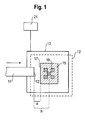
- Fig. 1 it is indicated how a part of the surveillance area is "seen" by a receiving arrangement 13 according to the invention.
- the total image recordable by means of the receiving arrangement 13 here corresponds to the size of the receiving arrangement 13.
- the image of a reference object 15 arranged in the monitoring area, for example a reflector, is likewise shown.
- the reference object 15 has a square shape.
- the reference feature is the in Fig. 1 left edge 17 of the reference object 15.
- the reference object 15 may additionally be provided with a coding 19, which in this example is provided in the form of a special arrangement of five smaller squares.
- Such an encoding 19 may alternatively or in addition to the edge 17 serve as a reference feature in the evaluation of the recordable by the receiving device 13 image.
- the reference object 15 and in particular its reference features 17 (edge) and 19 (coding) are formed both in relation to the surroundings also “seen” by the receiving arrangement 13 and in relation to an object 11 to be detected such that the reference features 17, 19 can be clearly identified during the evaluation of the image.
- Fig. 1 penetrates the object 11 in the arrow direction in the surveillance area.
- the front edge 12 of the article 11 is opened Image detected.
- the object edge 12 is located at a distance a from the edge 17 of the reference object 15 and at a distance b from the center of the coding 19 of the reference object 15.
- At least one of these distances a, b can be specified as the target position of the object 11 relative to the reference feature 17 or 19 of the reference object 15, and it is determined as soon as the image recorded by means of the receiving arrangement 13 is evaluated that the front Edge 12 of the article 11 in the respective distance a or b of the reference feature 17 and 19, an object detection signal can be output by means of an evaluation device 21 connected to the receiving device 13, for example, to trigger a switching operation.
- the target position of the object 11 relative to the reference object 15 corresponding to the distance a or b is in this case thus a switching position which must be determined as accurately as possible in order to ensure optimum operation of the respective machine or device at which the receiving device 13 comprehensive light barrier or other optoelectronic device is used.
- reference object 15 is Fig. 1 can be seen that, despite this change in position further an accurate determination of the switching position is possible because this does not change at the of the receiving assembly 13 "seen" image of the monitored area.
- the changed position is indicated by the dashed line receiving arrangement 13 '.
- the relative position between receiving arrangement 13 'and reference object 15 has changed from the original state.
- the relative position between penetrating object 11 and reference object 15 has not changed, and since it is this relative position between object 11 and reference object 15 or reference feature 17 and 19, respectively, by means of the receiving arrangement 13 'in the image recorded by means of the receiving arrangement 13' is evaluated, the determined in this evaluation distance a or b is invariant to changes in position of the receiving device 13 ', as long as these changes in position do not exceed a certain level.
- Fig. 2 shows a possible embodiment of a light barrier according to the invention, in which an at least largely collimated beam path is provided.
- the at least substantially parallel light beams are indicated by dashed lines, wherein the marginal rays 27 of the emitted light are shown by solid lines.
- a reflector 15 arranged in the monitoring region and serving as reference object is smaller than the emitted light beam limited by the marginal rays 27, ie. the reflector 15 is outshone by the emitted light.
- the light reflected by the reflector 15 is focused by a receiving lens 13 associated with a receiving lens 25 and received by a two-dimensional array of receiving elements, not shown, for example, photodiodes.
- the distribution of the received light on this receiver array is evaluated.
- An entering into the surveillance area object 11 interrupts a part of the Essentially parallel light rays.
- the depth of penetration of the object 11 and thus the position of the front edge 12 of the object relative to one of the edges 17 of the reflector 15 can be determined by evaluating the receiver array, since no light is incident on those receiving elements of the receiver array to which the in the absence of the article 11 undisturbed light rays would fall.
- the distance of the object 11 from the receiving device 13 has no relevant influence on the image picked up by the receiving device 13, i. Displacements of the article 11 along the optical axis of the system at the same depth of penetration have no effect on how the surveillance area is "seen" by the receiving array 13.
- a collimated beam path In the embodiment according to Fig. 3 on the one hand, one does not work with a collimated beam path. This means that from every point of the reflector 15 the light goes out in all directions. To simplify the illustration are in Fig. 3 only those light beams (edge beams 29) are drawn, which emanate from the edges 17 of the reflector 15. In the specific implementation of this embodiment, a possible continuous beam distribution is sought, in which the reflector 15 is outshined on all sides. Instead of a reflector 15 and a remittierendes reference object can be used.
- the receiving arrangement 13 is assigned an array of microlenses 23.
- the individual receiving elements of the receiver array of the receiving arrangement 13 are referred to as subpixels, while groups of subpixels, which are each assigned to one of the microlenses 23, are referred to as macropixels.
- each microlens 23 The light originating from the monitoring area is directed by each microlens 23 to the macropixel assigned to it, each consisting of a plurality of subpixels of the receiving arrangement 13, as shown in FIG Fig. 3 is schematically indicated in each case by the beam paths emanating from the microlenses 23. It is important that the light distribution within the macropixels is dependent on the beam path in the surveillance area. From the evaluation of the image recorded by means of the receiving arrangement 13, ie from the evaluation of the subpixels and additionally the light distributions within the macropixels, conclusions can be drawn about the subject situation in the monitored area.
- Fig. 4 shows two situations with an object 11 of the same penetration depth, the object 11 being in the first case (FIG. Fig. 4a ) near the reflector 15 and in the second case ( Fig. 4b ) is located near the receiving arrangement 13.
- the emanating from the upper edge 17 of the reflector 15 light rays are blocked by the reflector-like object 11, so that - as a comparison with Fig. 3 shows - the corresponding macropixels and their associated subpixels from this upper edge 17 received no light.
- Fig. 3 shows - the corresponding macropixels and their associated subpixels from this upper edge 17 received no light.
- each of the edges 17 of the reflector 15 outgoing light beams are partially blocked by the object 11.
- the evaluation of this light distribution not only allows a determination of the penetration depth of the object 11 but also of the distance of the object 11 from the receiving arrangement 13.
- Fig. 5 shows two situations with the same distance from the receiving device 13 Anlagendem article 11, but in the case of the Fig. 5a the penetration depth is smaller than in the case of Fig. 5b , From the comparison of Fig. 5a and Fig. 5b It becomes clear that the different influencing of the beam path within the surveillance area, which is dependent on the penetration depth, leads to different light distributions to the subpixels of the receiving arrangement 13 which are acted upon by light via the microlenses 23 under otherwise uniform conditions.
- an evaluation device connected to the receiving arrangement 13 can have a plurality of switching outputs for this purpose.
- a first output may switch when a near-object 11 is in accordance with FIG Fig. 4a has reached a predetermined penetration depth, while a second output switches when a close to the receiving assembly 13 penetrating object 11 according to Fig. 4b reaches a given penetration depth.
- the number of different object detection signals or switching positions and the number of different switching outputs of the evaluation device according to the invention basically arbitrary.
- Fig. 6 illustrates how with the invention various conditions can be linked together such that a switching signal is generated only if these conditions are present simultaneously.
- a switching signal is to be generated when a first object 11, which has a certain thickness and height, is in the position shown and at the same time a second object 11 'of lesser height and greater thickness occupies the illustrated further position.
- the presence of these conditions can be determined by determining the in Fig. 6 specified distances al, a2, A for the low and wide object 11 'and the distances b1, b2 and B for the high narrow object 11 with respect to serving as a reference feature edge 17 of the reference object 15 are determined. These distances relate to the upper as well as the direction of movement of the objects 11, 11 'indicated by the arrow through the monitoring area of the front and rear edges of the reference object 15.
- an object detection signal not only such geometrical properties of the objects 11, 11 'come into question.
- the evaluation of the image can also take place, for example, with regard to the reflection, remission or backscattering behavior of the surface of the object.
Landscapes
- Physics & Mathematics (AREA)
- Life Sciences & Earth Sciences (AREA)
- General Life Sciences & Earth Sciences (AREA)
- General Physics & Mathematics (AREA)
- Geophysics (AREA)
- Geophysics And Detection Of Objects (AREA)
Priority Applications (1)
| Application Number | Priority Date | Filing Date | Title |
|---|---|---|---|
| EP08010993A EP2136223A1 (fr) | 2008-06-17 | 2008-06-17 | Procédé et dispositif destinés à la saisie d'un objet |
Applications Claiming Priority (1)
| Application Number | Priority Date | Filing Date | Title |
|---|---|---|---|
| EP08010993A EP2136223A1 (fr) | 2008-06-17 | 2008-06-17 | Procédé et dispositif destinés à la saisie d'un objet |
Publications (1)
| Publication Number | Publication Date |
|---|---|
| EP2136223A1 true EP2136223A1 (fr) | 2009-12-23 |
Family
ID=40057736
Family Applications (1)
| Application Number | Title | Priority Date | Filing Date |
|---|---|---|---|
| EP08010993A Ceased EP2136223A1 (fr) | 2008-06-17 | 2008-06-17 | Procédé et dispositif destinés à la saisie d'un objet |
Country Status (1)
| Country | Link |
|---|---|
| EP (1) | EP2136223A1 (fr) |
Citations (7)
| Publication number | Priority date | Publication date | Assignee | Title |
|---|---|---|---|---|
| DE10229408A1 (de) * | 2002-06-29 | 2004-01-15 | Leuze Electronic Gmbh + Co Kg | Optischer Sensor |
| DE102004005460A1 (de) * | 2003-02-21 | 2004-09-09 | Leuze Electronic Gmbh + Co Kg | Optoelektronische Vorrichtung |
| DE102004008925A1 (de) * | 2003-02-28 | 2004-09-09 | Leuze Electronic Gmbh + Co Kg | Optoelektronische Vorrichtung |
| DE102004053219B3 (de) * | 2004-11-04 | 2006-04-06 | Leuze Electronic Gmbh & Co Kg | Optischer Sensor |
| DE102005060399A1 (de) | 2005-12-16 | 2007-06-21 | Sick Ag | Optoelektronische Vorrichtung und Verfahren zum Betreiben einer optoelektronischen Vorrichtung |
| WO2007085330A1 (fr) * | 2006-01-30 | 2007-08-02 | Abb Ab | Procédé et système permettant la supervision d'une zone de travail comportant un robot industriel |
| DE102006007764A1 (de) | 2006-02-20 | 2007-08-23 | Sick Ag | Optoelektronische Vorrichtung und Verfahren zu deren Betrieb |
-
2008
- 2008-06-17 EP EP08010993A patent/EP2136223A1/fr not_active Ceased
Patent Citations (7)
| Publication number | Priority date | Publication date | Assignee | Title |
|---|---|---|---|---|
| DE10229408A1 (de) * | 2002-06-29 | 2004-01-15 | Leuze Electronic Gmbh + Co Kg | Optischer Sensor |
| DE102004005460A1 (de) * | 2003-02-21 | 2004-09-09 | Leuze Electronic Gmbh + Co Kg | Optoelektronische Vorrichtung |
| DE102004008925A1 (de) * | 2003-02-28 | 2004-09-09 | Leuze Electronic Gmbh + Co Kg | Optoelektronische Vorrichtung |
| DE102004053219B3 (de) * | 2004-11-04 | 2006-04-06 | Leuze Electronic Gmbh & Co Kg | Optischer Sensor |
| DE102005060399A1 (de) | 2005-12-16 | 2007-06-21 | Sick Ag | Optoelektronische Vorrichtung und Verfahren zum Betreiben einer optoelektronischen Vorrichtung |
| WO2007085330A1 (fr) * | 2006-01-30 | 2007-08-02 | Abb Ab | Procédé et système permettant la supervision d'une zone de travail comportant un robot industriel |
| DE102006007764A1 (de) | 2006-02-20 | 2007-08-23 | Sick Ag | Optoelektronische Vorrichtung und Verfahren zu deren Betrieb |
Similar Documents
| Publication | Publication Date | Title |
|---|---|---|
| EP2492714B1 (fr) | Procédé de fonctionnement d'une barrière lumineuse de sécurité et barrière lumineuse de sécurité | |
| EP1927867B1 (fr) | Capteur optoélectronique à plusieurs plans et procédé de détection d'objets | |
| EP1494048B1 (fr) | Rideau de lumière | |
| DE102005033349B4 (de) | Optischer Sensor | |
| DE102007003024A1 (de) | Triangulationssensor mit Entfernungsbestimmung aus Lichtfleckposition und -form | |
| DE102014105746B4 (de) | Optoelektronischer Sensor und Verfahren zur Erfassung glänzender Objekte | |
| WO2001013029A1 (fr) | Dispositif pour proteger une zone dangereuse, notamment une zone dangereuse d'une machine fonctionnant de maniere automatisee | |
| DE102007003026A1 (de) | Optoelektronischer Sensor und Verfahren zur Objekterfassung in einem Überwachungsbereich | |
| WO2021228815A1 (fr) | Procédé d'étalonnage et/ou de réglage, et unité de commande pour un système lidar, système lidar et dispositif de travail | |
| EP1734383B1 (fr) | Barrière lumineuse destinée à la mesure d'un objet | |
| DE102005038019A1 (de) | Sensorvorrichtung zur Detektion eines Überhangs an der Beladung einer Trägereinrichtung | |
| EP1566588B1 (fr) | Rideau de lumière ou barrière optique avec dispositif d'alignement | |
| EP1041394A2 (fr) | Dispositif opto-électronique | |
| EP3324217A1 (fr) | Capteur optique et procédé de surveillance d'une zone de surveillance | |
| DE102006050189A1 (de) | Lichtgitter mit Ausrichtlichtsender und Verfahren zum Ausrichten | |
| EP2136223A1 (fr) | Procédé et dispositif destinés à la saisie d'un objet | |
| DE10142362A1 (de) | Optoelekronische Überwachungseinrichtung | |
| EP2410354B1 (fr) | Procédé de fonctionnement d'une barrière lumineuse de sécurité et barrière lumineuse de sécurité | |
| EP3104198A1 (fr) | Capteur optoelectronique | |
| EP1906368B1 (fr) | Système de sécurité optoélectronique | |
| EP2312340A1 (fr) | Procédé de fonctionnement d'un capteur optoélectronique et capteur optoélectronique | |
| DE102017103791B4 (de) | Optoelektronischer Sensor und Verfahren zur Erfassung von Objekten | |
| EP1811427A1 (fr) | Procédé et dispositif pour la surveillance d'un domaine | |
| EP1134594B1 (fr) | Procédé et dispositif de détection de zones de carré d'objet | |
| DE202008009090U1 (de) | Optoelektronischer Sensor |
Legal Events
| Date | Code | Title | Description |
|---|---|---|---|
| PUAI | Public reference made under article 153(3) epc to a published international application that has entered the european phase |
Free format text: ORIGINAL CODE: 0009012 |
|
| AK | Designated contracting states |
Kind code of ref document: A1 Designated state(s): AT BE BG CH CY CZ DE DK EE ES FI FR GB GR HR HU IE IS IT LI LT LU LV MC MT NL NO PL PT RO SE SI SK TR |
|
| AX | Request for extension of the european patent |
Extension state: AL BA MK RS |
|
| 17P | Request for examination filed |
Effective date: 20100310 |
|
| 17Q | First examination report despatched |
Effective date: 20100416 |
|
| AKX | Designation fees paid |
Designated state(s): AT BE BG CH CY CZ DE DK EE ES FI FR GB GR HR HU IE IS IT LI LT LU LV MC MT NL NO PL PT RO SE SI SK TR |
|
| 18R | Application refused |
Effective date: 20180719 |