EP1821355A2 - Batterie und Verfahren zum Montieren der Batterie - Google Patents
Batterie und Verfahren zum Montieren der Batterie Download PDFInfo
- Publication number
- EP1821355A2 EP1821355A2 EP07250207A EP07250207A EP1821355A2 EP 1821355 A2 EP1821355 A2 EP 1821355A2 EP 07250207 A EP07250207 A EP 07250207A EP 07250207 A EP07250207 A EP 07250207A EP 1821355 A2 EP1821355 A2 EP 1821355A2
- Authority
- EP
- European Patent Office
- Prior art keywords
- safety valve
- battery
- peripheral edge
- casing
- edge portion
- Prior art date
- Legal status (The legal status is an assumption and is not a legal conclusion. Google has not performed a legal analysis and makes no representation as to the accuracy of the status listed.)
- Granted
Links
Images


Classifications
-
- H—ELECTRICITY
- H01—ELECTRIC ELEMENTS
- H01M—PROCESSES OR MEANS, e.g. BATTERIES, FOR THE DIRECT CONVERSION OF CHEMICAL ENERGY INTO ELECTRICAL ENERGY
- H01M50/00—Constructional details or processes of manufacture of the non-active parts of electrochemical cells other than fuel cells, e.g. hybrid cells
- H01M50/30—Arrangements for facilitating escape of gases
- H01M50/342—Non-re-sealable arrangements
- H01M50/3425—Non-re-sealable arrangements in the form of rupturable membranes or weakened parts, e.g. pierced with the aid of a sharp member
-
- H—ELECTRICITY
- H01—ELECTRIC ELEMENTS
- H01M—PROCESSES OR MEANS, e.g. BATTERIES, FOR THE DIRECT CONVERSION OF CHEMICAL ENERGY INTO ELECTRICAL ENERGY
- H01M50/00—Constructional details or processes of manufacture of the non-active parts of electrochemical cells other than fuel cells, e.g. hybrid cells
- H01M50/10—Primary casings; Jackets or wrappings
- H01M50/183—Sealing members
- H01M50/19—Sealing members characterised by the material
- H01M50/193—Organic material
-
- H—ELECTRICITY
- H01—ELECTRIC ELEMENTS
- H01M—PROCESSES OR MEANS, e.g. BATTERIES, FOR THE DIRECT CONVERSION OF CHEMICAL ENERGY INTO ELECTRICAL ENERGY
- H01M50/00—Constructional details or processes of manufacture of the non-active parts of electrochemical cells other than fuel cells, e.g. hybrid cells
- H01M50/10—Primary casings; Jackets or wrappings
- H01M50/183—Sealing members
- H01M50/186—Sealing members characterised by the disposition of the sealing members
-
- H—ELECTRICITY
- H01—ELECTRIC ELEMENTS
- H01M—PROCESSES OR MEANS, e.g. BATTERIES, FOR THE DIRECT CONVERSION OF CHEMICAL ENERGY INTO ELECTRICAL ENERGY
- H01M50/00—Constructional details or processes of manufacture of the non-active parts of electrochemical cells other than fuel cells, e.g. hybrid cells
- H01M50/50—Current conducting connections for cells or batteries
- H01M50/543—Terminals
- H01M50/547—Terminals characterised by the disposition of the terminals on the cells
- H01M50/55—Terminals characterised by the disposition of the terminals on the cells on the same side of the cell
-
- H—ELECTRICITY
- H01—ELECTRIC ELEMENTS
- H01M—PROCESSES OR MEANS, e.g. BATTERIES, FOR THE DIRECT CONVERSION OF CHEMICAL ENERGY INTO ELECTRICAL ENERGY
- H01M50/00—Constructional details or processes of manufacture of the non-active parts of electrochemical cells other than fuel cells, e.g. hybrid cells
- H01M50/50—Current conducting connections for cells or batteries
- H01M50/543—Terminals
- H01M50/552—Terminals characterised by their shape
- H01M50/553—Terminals adapted for prismatic, pouch or rectangular cells
-
- H—ELECTRICITY
- H01—ELECTRIC ELEMENTS
- H01M—PROCESSES OR MEANS, e.g. BATTERIES, FOR THE DIRECT CONVERSION OF CHEMICAL ENERGY INTO ELECTRICAL ENERGY
- H01M50/00—Constructional details or processes of manufacture of the non-active parts of electrochemical cells other than fuel cells, e.g. hybrid cells
- H01M50/50—Current conducting connections for cells or batteries
- H01M50/543—Terminals
- H01M50/564—Terminals characterised by their manufacturing process
- H01M50/566—Terminals characterised by their manufacturing process by welding, soldering or brazing
-
- Y—GENERAL TAGGING OF NEW TECHNOLOGICAL DEVELOPMENTS; GENERAL TAGGING OF CROSS-SECTIONAL TECHNOLOGIES SPANNING OVER SEVERAL SECTIONS OF THE IPC; TECHNICAL SUBJECTS COVERED BY FORMER USPC CROSS-REFERENCE ART COLLECTIONS [XRACs] AND DIGESTS
- Y02—TECHNOLOGIES OR APPLICATIONS FOR MITIGATION OR ADAPTATION AGAINST CLIMATE CHANGE
- Y02E—REDUCTION OF GREENHOUSE GAS [GHG] EMISSIONS, RELATED TO ENERGY GENERATION, TRANSMISSION OR DISTRIBUTION
- Y02E60/00—Enabling technologies; Technologies with a potential or indirect contribution to GHG emissions mitigation
- Y02E60/10—Energy storage using batteries
-
- Y—GENERAL TAGGING OF NEW TECHNOLOGICAL DEVELOPMENTS; GENERAL TAGGING OF CROSS-SECTIONAL TECHNOLOGIES SPANNING OVER SEVERAL SECTIONS OF THE IPC; TECHNICAL SUBJECTS COVERED BY FORMER USPC CROSS-REFERENCE ART COLLECTIONS [XRACs] AND DIGESTS
- Y10—TECHNICAL SUBJECTS COVERED BY FORMER USPC
- Y10T—TECHNICAL SUBJECTS COVERED BY FORMER US CLASSIFICATION
- Y10T29/00—Metal working
- Y10T29/49—Method of mechanical manufacture
- Y10T29/49002—Electrical device making
- Y10T29/49108—Electric battery cell making
Definitions
- the invention relates to a battery that includes a safety valve that is opened when pressure in the battery increases, and a method of assembling the battery.
- a sealed battery is provided with a safety valve that opens a part of a casing to prevent an excessive increase in the pressure in the battery when the pressure in the battery increases.
- Japanese Patent Application Publication No. JP-A-10-106524 (hereinafter, referred to as "Publication No. 10-106524 ”) describes a device in which a safety valve is formed in a casing.
- a thin area is formed in a cover made of a metallic plate.
- the thin area is the thinnest area in the cover.
- the thin area functions as the safety valve.
- Japanese Patent Application Publication No. JP-A-9-293490 (hereinafter, referred to as "Publication No. 9-293490 ”) describes a battery and a method of assembling the battery, in which the peripheral edge portion of a safety valve is welded to the peripheral edge portion around a vent hole of a casing.
- the safety valve When the safety valve is formed in a part of the casing made of metal as described in Publication No. 10-106524 , or when the safety valve is welded to the casing made of metal as described in Publication No. 9-293490 , impacts applied to the casing, or vibrations caused in the casing are directly transmitted to the safety valve.
- the safety valve is more fragile than the body of the casing. If the impacts applied to the casing are directly transmitted to the safety valve, the safety valve may be broken. If the vibrations caused in the casing are directly transmitted to the safety valve, the safety valve may deteriorate. If the safety valve deteriorates, the safety valve may be opened even when the pressure in the battery is below a predetermined value.
- the invention provides a battery in which impacts applied to a casing or vibrations caused in the casing are hardly transmitted to a safety valve, and the safety valve is protected from the impacts applied to the casing or the vibrations caused in the casing, and a method of assembling the battery.
- a first aspect of the invention relates to a battery that includes a casing made of metal, and a safety valve made of a thin plate.
- the casing includes a vent hole that provides communication between the inside of the battery and the outside of the battery.
- the safety valve closes the vent hole of the casing.
- a synthetic resin seal member is provided between the peripheral edge portion around the vent hole and the peripheral edge portion of the safety valve. The seal member connects the peripheral edge portion around the vent hole of the casing to the peripheral edge portion of the safety valve such that the peripheral edge portion around the vent hole does not contact the peripheral edge portion of the safety valve.
- the safety valve is configured to be broken when the pressure in the battery reaches a predetermined value.
- the safety valve is more fragile than any other area that forms the outer periphery of the battery (i.e., the casing). If impacts applied to the casing from the outside of the battery are directly transmitted to the safety valve, the safety valve may be broken. If vibrations caused in the casing are directly transmitted to the safety valve continuously or intermittently for a long time, the safety valve may deteriorate. As a result, the safety valve may be broken even when the pressure in the battery is below a predetermined value.
- the seal member absorbs the impacts applied to the area other than the safety valve in the battery, or the vibrations caused in the area other than the safety valve in the battery, before the impacts or vibrations are transmitted to the safety valve.
- the impacts or vibrations are transmitted to the safety valve. Accordingly, in the first aspect, the safety valve is hardly broken by the impacts applied from the outside of the battery. Also, even if vibrations are continuously or intermittently caused in the casing, the safety valve hardly deteriorates.
- any battery that includes a safety valve and a casing made of metal may be employed as the battery according to the first embodiment.
- the type and outer shape of the battery are not limited to a particular type and a particular outer shape.
- the invention may be applied to a primary battery, a secondary battery, and a capacitor.
- the shape of the casing is not limited to a particular shape.
- the invention may be applied to a square battery, a cylindrical battery, a button battery, and a plate battery.
- the safety valve may be formed in any area in the casing.
- the area where the safety valve is formed is not limited to a particular area.
- the casing includes a housing that has an opening, and a cover that closes the opening
- the safety valve may be formed in the cover, or an area in the housing.
- the safety valve may be disposed in an appropriate area taking into account the conditions for the use of the battery, or the conditions for the installation of the battery.
- the safety valve may have any configuration, that is, the configuration of the safety valve is not limited to a particular configuration, as long as the safety valve is made of a thin plate that is preferentially broken when the pressure in the battery increases.
- the same material as that used to form the casing may be selected to form the safety valve.
- a plate thinner than the wall portion of the casing may be employed to form the safety valve.
- a groove may be formed on the surface of the thin plate so that the groove is broken when the pressure in the battery increases.
- the safety valve may have any shape, as long as the safety valve and the seal member close the vent hole of the casing. That is, the shape of the safety valve is not limited to a particular shape.
- the contour of the safety valve may be substantially the same as, or slightly larger than, or slightly smaller than the contour of the vent hole of the casing.
- the seal member is not limited to a particular resin.
- Typical synthetic resins may include rubber-type polymers such as silicon rubber and isoprene rubber, and various elastomers.
- the seal member may be made of synthetic resin material resistant to organic solvent that is used to generate the electrolyte.
- the seal member may be made of polyolefin resins such as polypropylene (PP) resins and polyethylene (PE) resins, and crystal engineering plastic material such as polyphenylene sulfide (PPS) resins and liquid crystal polymer (LCP) compounds.
- the synthetic resin material resistant to a strong alkali aqueous solution which is the electrolyte, may be selected to form the seal member.
- the material generated by kneading an ordinary synthetic resin and a rubber polymer or an elastomer may be used.
- the seal member may extend from the area outside the casing to the area inside the casing.
- the peripheral edge portion around the vent hole of the casing may be connected to the peripheral edge portion of the safety valve such that the peripheral edge portion around the vent hole and the peripheral edge portion of the safety valve are inserted in the seal member.
- the peripheral edge portion around the vent hole of the casing and the peripheral edge portion of the safety valve are coated with the seal member that has the effect of absorbing impacts. Therefore, vibrations or impacts are less likely to be transmitted to the safety valve. Also, the areas where the seal member contacts the peripheral edge portion around the vent hole and the peripheral edge portion of the safety valve are increased. Thus, the safety valve is more solidly connected to the casing.
- the seal member may extend on at least one of the outside and the inside of the surface of the casing, in which the vent hole is formed, such that the at least one of the outside and the inside of the surface is coated with the seal member.
- the resin coating layer When the resin coating layer is formed around the safety valve, the resin coating layer attenuates impacts applied to the casing or vibrations caused in the casing. Thus, the impacts or vibrations are effectively attenuated before transmitted to the safety valve.
- This configuration effectively prevents the safety valve from being damaged or deteriorated due to the impacts or vibrations applied from the outside of the battery.
- a second aspect of the invention relates to a method of assembling a battery.
- the method includes preparing a casing made of metal, which has a vent hole that provides communication between the area inside a battery and the area outside the battery; preparing a safety valve made of a thin metallic plate; and connecting the peripheral edge portion around the vent hole of the casing to the peripheral edge portion of the safety valve via a seal member made of synthetic resin such that the peripheral edge portion around the vent hole does not contact the peripheral edge portion of the safety valve.
- the casing may include a cover and a housing.
- the cover has the vent hole, and holes through which a positive-electrode terminal and a negative-electrode terminal extend.
- the housing includes an opening, a sidewall that forms the peripheral edge of the opening, and a bottom wall that is opposite to the opening.
- the peripheral edge portion around the vent hole of the casing may be connected to the peripheral edge portion of the safety valve by an insert molding process.
- the casing and the safety valve may be set in an injection mold according to a predetermined positional relation, and then synthetic resin may be filled in the injection mold to form the seal member by injection molding.
- the battery 10 includes an aluminum casing 18 that includes the cover 20 and a housing 12.
- Elements for generating electric power (hereinafter, referred to as "power-generation elements"), such as an electrode assembly 16 and an electrolyte, are housed in the casing 18.
- the electrode assembly 16 is a roll-type electrode assembly formed by stacking a positive-electrode sheet and a negative-electrode sheet via a separator, and rolling the stacked positive-electrode sheet, negative-electrode sheet, and the separator such that the electrode assembly 16 has a flat shape.
- the electrode assembly 16 (refer to FIG. 3) and the electrolyte are the power-generation elements in the lithium-ion secondary battery 10.
- the positive-electrode sheet includes a current-collecting foil made of aluminum. Layers of positive-electrode active material are provided on the front and back sides of the current-collecting foil.
- the positive-electrode sheet is connected to a positive-electrode terminal 24.
- the positive-electrode terminal 24 is made of an aluminum plate.
- the positive terminal 24 is fixed to the cover 20.
- the negative-electrode sheet includes a current-collecting foil made of copper. Layers of negative-electrode active material are provided on the front and back sides of the current-collecting foil.
- the negative-electrode sheet is connected to a negative-electrode terminal 26.
- the negative-electrode terminal 26 is made of a copper plate.
- the negative-electrode terminal 26 is fixed to the cover 20.
- the separator is a porous polyolefin sheet. The separator is impregnated with the electrolyte.
- the electrolyte is the power-generation element in the battery 10.
- a conventionally-known liquid non-aqueous electrolyte or gelled polymer electrolyte for the lithium-ion secondary battery may be employed as the electrolyte.
- the electrolyte generated by dissolving lithium hexafluoride (LiPH 6 ), which is lithium salt, in mixed solvent of diethyl carbonate (DEC) and ethylene carbonate (EC) (e.g., mixed solvent generated by mixing DEC and EC at the mass ratio of 7: 3).
- LiPH 6 lithium hexafluoride
- EC ethylene carbonate
- the housing 12 of the casing 18 is a substantially rectangular parallelepiped.
- four sidewalls form the peripheral edge of the rectangular opening that has rounded corners.
- the four sidewalls are composed of a pair of sidewalls having a wide width, and a pair of sidewalls having a narrow width.
- the sidewalls having a wide width correspond to the long sides of the opening.
- the sidewalls having a narrow width correspond to the short sides of the opening.
- the adjacent sidewalls are continuous with each other. The areas where the sidewalls contact each other are rounded.
- the cover 20 of the casing 18 is rectangular, and has rounded corners.
- the cover 20 is connected to the housing 12 such that the cover 20 is fitted in the opening of the housing 12.
- the cover 20 has a through-hole 21 for the positive-electrode terminal 24, and a through-hole 23 for the negative-electrode terminal 26.
- the positive-electrode terminal 24 and the negative-electrode terminal 26 extend from the electrode assembly 16 in the battery 10 through the through-holes 21 and 23, respectively.
- a vent hole 25 is formed at the center of the cover 20.
- the vent hole 25 is rectangular, and has rounded corners.
- the safety valve 30 and a seal member 28 are connected to the vent hole 25 such that the vent hole 25 is closed.
- Grooves 32 are formed in the safety valve 30. The grooves 32 cross each other at the substantially center position in the safety valve 30. If the pressure in the battery 10 increases, the area where the grooves 32 cross each other will break.
- FIG. 3 is a sectional view taken along line III-III.
- the safety valve 30 is provided between the positive-electrode terminal 24 and the negative-electrode terminal 26.
- the contour of the safety valve 30 is substantially the same as the contour of the vent hole 25 of the cover 20.
- the safety valve 30 is provided in the battery 10 at the position inside the cover 20. That is, the safety valve 30 is provided at the position lower than the surface of the cover 20.
- the seal member 28 connects the peripheral edge portion around the vent hole 25 to the peripheral edge portion of the safety valve 30.
- the seal member 28 may be made of polyphenylene sulfide (PPS), which is capable of absorbing vibrations and impacts.
- PPS polyphenylene sulfide
- PP polypropylene
- PE polyethylene
- LCP liquid crystal polymer
- LCP and PPS have high heat resistance
- LCP and PPS have high resistance to organic solvent that is used to generate the electrolyte.
- the seal member 28 may be formed using crystal engineering plastic material, such as LCP and PPS.
- the seal member 28 is provided along the entire peripheral edge portion of the safety valve 30, and along the entire peripheral edge portion around the vent hole 25.
- the seal member 28 has a vertically-long oval cross section.
- the peripheral edge portion of the safety valve 30 is inserted in the seal member 28.
- the peripheral edge portion around the vent hole 25, which is a part of the cover 20, is also inserted in the seal member 28. Because the seal member 28 is disposed between the safety valve 30 and the cover 20, the safety valve 30 does not contact the cover 20.
- An insulation member 29 is disposed between the positive-electrode terminal 24 and the cover 20.
- the insulation member 29 is also disposed between the negative-electrode terminal 26 and the cover 20. Because the insulation members 29 are disposed between a metallic plate 22 and the terminals 24 and 26, the terminals 24 and 26 are insulated from each other.
- the housing 12 made of metal includes the rectangular opening that has rounded corners, the four sidewalls that form the peripheral edge of the opening, and a bottom wall that is opposite to the opening.
- the cover 20 is assembled according to the following procedure.
- the metallic plate 22 has the through-holes 21 and 23, and the vent hole 25.
- the positive-electrode 24 extends through the through-hole 21, and the negative-electrode 26 extends through the through-hole 23.
- the metallic plate 22 has another through-hole (not shown), through which the electrolytic solution is supplied.
- the contour of the metallic plate 22 is substantially the same as the contour of the opening of the housing 12.
- the surface of the peripheral edge portion around the vent hole 25, and the surface of the area near the peripheral edge portion are roughened. This allows the seal member 28 to be tightly connected to the peripheral edge portion around the vent hole 25.
- the method of roughening the surface is not limited to a particular method.
- the positive-electrode terminal 24 and the negative-electrode terminal 26 are passed through the through-holes 21 and 23, respectively. Then, the positive-electrode terminal 24 and the negative-electrode terminal 26 are fixed to the metallic plate 22.
- the insulation members 29 are disposed between the positive-electrode terminal 24 and the negative-electrode terminal 26 such that the positive-electrode terminal 24 and the negative-electrode terminal 26 are insulated from each other.
- the safety valve 30 is connected to the cover 20 using the seal member 28.
- the cover 20, safety valve 30, and seal member 28 are connected to each other by an insert molding process.
- the cover 20 and safety valve 30 are set in an injection mold according to a predetermined positional relation, and then synthetic resin is filled in the injection mold to form the seal member 28 by injection molding.
- the cover 20, safety valve 30, and seal member 28 are solidly connected to each other by this insert molding process.
- the electrode assembly 16 which has been assembled beforehand, is connected to the positive-electrode terminal 24 and the negative-electrode terminal 26 that extend through the through-holes 21 and 23 of the cover 20.
- the positive-electrode terminal 24 is welded to the positive-electrode sheet of the electrode assembly 16.
- the negative-electrode terminal 26 is welded to the negative-electrode sheet of the electrode assembly 16. Because the electrode assembly 16 is assembled according to a conventional method, description of the method of assembling the electrode assembly 16 is omitted.
- the electrode assembly 16 connected to the cover 20 is inserted in the housing 12 through the opening of the housing 12.
- the cover 20 is fitted in the opening of the housing 12.
- the peripheral edge portion of the cover 20 may be laser welded to the peripheral edge portion around the opening of the housing 12 at the welding area 14 where they overlap each other.
- the electrolyte is supplied through the electrolyte-inlet formed in the cover 20.
- the electrolyte-inlet is tightly closed.
- a vibration test may be conducted on the battery 10 according to the embodiment.
- the vibration test may be conducted according to a test method specified in the recommendations for transport of hazardous material issued by United Nations.
- a comparative battery may be used.
- the comparative battery has the same specifications as those of the battery 10 according to the embodiment.
- a cover is directly connected to a safety valve by welding.
- the vibration test will be described more specifically.
- the sine-curve signals from 7 to 200 Hz which are obtained by log sweep, are used to cause vibrations.
- the conditions relating to the log sweep rate of the vibrations in the test will be described.
- the vibrations are accelerated at the peak acceleration of 1G (approximately 9.8 m/s 2 ) until the frequency of the vibrations reach 7 to 18 Hz.
- the frequency may be increased to 50 Hz while maintaining the amplitude at 0.8 mm (total displacement: 1.6 mm), and changing the peak acceleration from 1 G to 8G.
- the frequency is increased to 200 Hz while maintaining the peak acceleration at 8G.
- the frequency is maintained at 200 Hz for a while.
- the frequency of the vibrations is decreased from 200 Hz to 7 Hz.
- the above-described process is performed in one cycle of the vibration test.
- the vibration direction is changed among the three directions (the X-axis direction, Y-axis direction, and Z-axis direction in a three-dimensional coordinate) in the test. Twelve cycles of the test are conducted for each of the cases where the vibration direction is the X-axis direction, Y-axis direction, and Z-axis direction.
- the safety valve 30 is connected to the cover 20 via the seal member 28 such that safety valve 30 does not contact the cover 20. It is considered that the vibrations applied from the outside of the battery 10 are not directly transmitted to the safety valve 30, because the seal member 28 absorbs the vibrations. Even when strong vibrations are applied to the battery 10, the safety valve 30 is hardly damaged.
- the battery 10 is highly resistant to the force applied from the outside of the battery 10. Thus, the safety valve 30 is broken only when the pressure in the battery 10 increases, that is, the force is applied from the inside of the battery 10. As a result, the safety valve 30 is hardly broken when the pressure in the battery 10 is below a predetermined value.
- a plurality of small cracks are formed in the safety valve in the comparative battery.
- the cover is directly connected to the safety valve by welding.
- the vibrations applies from the outside of the battery are transmitted to the safety valve, without weakening the vibrations.
- the safety valve is thinner than the casing, the safety valve is easily damaged by the force applied from the outside of the battery 10. If small cracks are formed in the safety valve, the safety valve may be broken even when the pressure in the battery is below the predetermined value.
- the seal member 28 which has the effect of absorbing impacts, between the safety valve 30 and the cover 20, it is possible to prevent the safety valve 30 from being broken or damaged by the force applied from the outside of the battery.
- the safety valve 30 is broken and the gas in the battery 10 is released when the pressure in the battery 10 reaches the predetermined value.
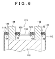
- the configuration of the battery 110 in the second embodiment is the same as that of the battery 10 in the first embodiment, except for a positive-electrode terminal 124 and a negative-electrode terminal 126 that extend through the through-holes of the cover 120, and a seal member 135. Therefore, the description of the same components as those of the battery 10 in the first embodiment will be omitted.
- the battery 110 includes an aluminum casing 118 that includes the cover 120 and a housing 112.
- the power-generation elements such as an electrode assembly 116 and the electrolyte, are housed.
- the shape of the housing 112 is the same as that of the housing 12 of the battery 10 in the first embodiment. Therefore, the description of the shape of the housing 112 is omitted.
- the cover 120 of the casing 118 is rectangular, and has rounded corners.
- the cover 120 is connected to the housing 112 such that the cover 120 is fitted in the opening of the housing 112.
- the cover 120 has the through-hole 121 for the positive-electrode terminal 124, and the through-hole 123 for the negative-electrode terminal 126.
- the through-holes 121 and 123 are formed such that the outer peripheries of the through-holes 121 and 123 are slightly greater than the outer peripheries of the terminals 124 and 126.
- the terminals 124 and 126 extend from the electrode assembly 116 in the battery 110 through the through-holes 121 and 123.
- the seal member 135 is formed in the cover 120.
- the seal member 135 includes a coating area 127, a seal portion 128, and terminal seal portions 134 and 136.
- the coating area 127 covers the both surfaces of a metallic plate 122.
- the seal portion 128 connects the peripheral edge portion of the safety valve 130 to the peripheral edge portion around a vent hole 125.
- the terminal seal portion 134 connects the peripheral edge portion of the terminal 124 to the peripheral edge portion around the through-hole 121.
- the terminal seal portion 136 connects the peripheral edge portion of the terminal 126 to the peripheral edge portion around the through-hole 123.
- the coating area 127 covers the outer surface and inner surface of the metallic plate 122.
- the coating area 127 greatly attenuates impacts or vibrations applied from the outside of the battery 110, before they are transmitted to the safety valve 130.
- the seal portion 128 is disposed in the inner area of the cover 120.
- the resin in the peripheral edge portion around the vent hole 125 is thicker than the resin in the coating area 127.
- the peripheral edge portion of the safety valve 130 is connected to the peripheral edge portion around the opening 125 of the cover 120 such that the entire peripheral edge portion of the safety valve 130 is inserted in the seal portion 128.
- the vent hole 125 of the cover 120 is closed.
- the seal portion 128 connects the peripheral edge portion around the vent hole 125 to the peripheral edge portion of the safety valve 130 such that the peripheral edge portion around the vent hole 125 does not contact the peripheral edge portion of the safety valve 130.
- the terminal seal portions 134 and 136 are formed to fill the gaps between the terminals 124 and 126 and the through-holes 121 and 123, respectively.
- the positive-electrode terminal 124 and the negative-electrode terminal 126 are insulated from each other by the terminal seal portions 134 and 136.
- the terminals 124 and 126 extend from the inside of the casing 118 to the outside of the casing 118. In a configuration according to the second embodiment that lacks seal members, loads such as impacts or vibrations are easily applied from the outside of the battery to the areas where the casing 118 is connected to the terminals 124 and 126.
- the resin areas i.e., the terminal seal portions 134 and 136) are formed between the peripheral edge portions around the through-holes 121 and 123, and the terminals 124 and 126, the areas where the casing 118 is connected to the terminals 124 and 126 are hardly damaged.
- Grooves 132 are formed in the safety valve 130. The grooves 132 cross each other at the substantially center position in the safety valve 130. If the pressure in the battery 110 increases, the area where the grooves 132 cross each other will break.
- the method of assembling the battery 110 in the second embodiment is the same as the method of assembling the battery 10 in the first embodiment, except for the processes of assembling the cover 120, the safety valve 130, and the coating area 127. Therefore, the description of the same processes as those in the method in the first embodiment will be omitted.
- the cover 120 is assembled according to the following procedure.
- the metallic plate 122 has the through-hole 121, the through-hole 123, and the vent hole 125.
- the positive-electrode 124 extends through the through-hole 121, and the negative-electrode 126 extends through the through-hole 123.
- the metallic plate 122 has another through-hole (not shown), through which the electrolytic solution is supplied.
- the contour of the metallic plate 122 is substantially the same as the contour of the opening of the housing 112.
- the surface of the entire metallic plate 122 is roughened.
- the seal member 135, which is formed on the surface of the metallic plate 122 is tightly connected to the metallic plate 122.
- the positive-electrode terminal 124, negative-electrode terminal 126, safety valve 130, and metallic plate 122 are integrated with each other.
- the positive-electrode terminal 124 and the negative-electrode terminal 126 are passed through the through-holes 121 and 123 in the metallic plate 122, respectively.
- the safety valve 130 is fitted in the vent hole 125.
- the seal member 135 is formed, and the metallic plate 122, positive-electrode terminal 124, negative-electrode terminal 126, and safety valve 130 are connected to each other by this insert molding process. That is, the cover 120, safety valve 130, positive-electrode terminal 124, and negative-electrode terminal 126 are solidly connected to each other by the insert molding process. Thus, they are integrated with each other via the seal member 135.
- the electrode assembly 116 which has been assembled beforehand, is connected to the positive-electrode terminal 124 and the negative-electrode terminal 126 that extend through the through-holes 121 and 123 of the cover 120.
- the positive-electrode terminal 124 is welded to the positive-electrode sheet of the electrode assembly 116.
- the negative-electrode terminal 126 is welded to the negative-electrode sheet of the electrode assembly 116.
- the electrode assembly 116 which is connected to the cover 120, is inserted in the housing 112 through the opening of the housing 112.
- the cover 120 is fitted in the opening of the housing 112.
- the peripheral edge portion of the cover 120 may be laser welded to the peripheral edge portion around the opening of the housing 112 at a welding area 114 where the peripheral edge portion of the cover 120 overlaps the peripheral edge portion around the opening of the housing 112.
- the electrolyte is supplied through the electrolyte-inlet formed in the cover 120.
- the electrolyte-inlet is tightly closed.
- the electrode assembly housed in the casing is not limited to a particular electrode assembly, as long as the electrode assembly is the power-generation element that stores and releases a predetermined amount of electric power.
- the shape and size of the electrode assembly are not limited to a particular shape and particular size. That is, the electrode assembly may have any shape and any size.
- Typical power-generation elements include various types of primary battery (e.g., a lithium primary battery and a manganese battery), a secondary battery (e.g., a lithium-ion secondary batter, and a nickel-hydrogen battery), or a capacitor (e.g., an electrical double layer capacitor).
- the size and shape of the casing of the battery according to the invention may be appropriately changed according to the type, size, shape, and the like of the electrode assembly to be housed in the casing.
- the casing may be made of metallic material that is resistant to the product of a reaction caused by the power-generation elements such as the electrolyte and the electrode assembly.
- the casing may be made of aluminum, steel, or the like.
- a thin resin coating may be formed on the inner side and outer side of the casing.
- the resin used to form the layer that seals the gap between the safety valve and the vent hole may be selected according to the specification temperature of the battery, and/or the liquid characteristic of the electrolyte.
- polyolefin resins such as polyethylene and polypropylene, and ethylene-propylene-diene copolymer (EPDM)may be used.
- EPDM ethylene-propylene-diene copolymer
- Polyphenylene sulfide (PPS) resins, polystyrene resins, polyimide resins, polyamide-imide resins, fluorocarbon resins, polyether ether keton (PEEK) resins, polyether sulfone (PES) resins, and the like may be also used.
- alkali-resistant resins may be used.
- PTFE polytetrafluoroethylene
- polyamide resins polyamide resins
- PEEK resins may be selected.
Landscapes
- Chemical & Material Sciences (AREA)
- Chemical Kinetics & Catalysis (AREA)
- Electrochemistry (AREA)
- General Chemical & Material Sciences (AREA)
- Gas Exhaust Devices For Batteries (AREA)
- Sealing Battery Cases Or Jackets (AREA)
Applications Claiming Priority (1)
| Application Number | Priority Date | Filing Date | Title |
|---|---|---|---|
| JP2006015514A JP4996857B2 (ja) | 2006-01-24 | 2006-01-24 | 電池 |
Publications (3)
| Publication Number | Publication Date |
|---|---|
| EP1821355A2 true EP1821355A2 (de) | 2007-08-22 |
| EP1821355A3 EP1821355A3 (de) | 2010-10-20 |
| EP1821355B1 EP1821355B1 (de) | 2017-01-18 |
Family
ID=37907200
Family Applications (1)
| Application Number | Title | Priority Date | Filing Date |
|---|---|---|---|
| EP07250207.3A Ceased EP1821355B1 (de) | 2006-01-24 | 2007-01-19 | Batterie und Verfahren zum Montieren der Batterie |
Country Status (4)
| Country | Link |
|---|---|
| US (1) | US7655347B2 (de) |
| EP (1) | EP1821355B1 (de) |
| JP (1) | JP4996857B2 (de) |
| CN (1) | CN100477339C (de) |
Cited By (5)
| Publication number | Priority date | Publication date | Assignee | Title |
|---|---|---|---|---|
| EP2482363A1 (de) * | 2011-01-31 | 2012-08-01 | SB LiMotive Co., Ltd. | Sekundärbatterie |
| EP2422389A4 (de) * | 2009-04-22 | 2014-04-02 | Chun-Chieh Chang | Stromsammelabdichtung für langlebige lithiumionenzellen |
| WO2014195048A1 (de) * | 2013-06-04 | 2014-12-11 | Robert Bosch Gmbh | Sicherheitsventil zum schutz einer galvanischen zelle vor schädigendem überdruck sowie zellgehäusedeckel und galvanische zelle mit sicherheitsventil |
| WO2015117716A1 (de) * | 2014-02-10 | 2015-08-13 | Robert Bosch Gmbh | Vorrichtung zur erhöhung der sicherheit beim gebrauch von batteriesystemen |
| EP3772120A1 (de) * | 2019-07-30 | 2021-02-03 | Contemporary Amperex Technology Co., Limited | Batteriemodul, sekundärbatterie und kappenplattenanordnung dafür |
Families Citing this family (13)
| Publication number | Priority date | Publication date | Assignee | Title |
|---|---|---|---|---|
| US20090186169A1 (en) * | 2008-01-17 | 2009-07-23 | Harris Corporation | Three-dimensional liquid crystal polymer multilayer circuit board including battery and related methods |
| US9117602B2 (en) | 2008-01-17 | 2015-08-25 | Harris Corporation | Three-dimensional liquid crystal polymer multilayer circuit board including membrane switch and related methods |
| US8778124B2 (en) * | 2008-01-17 | 2014-07-15 | Harris Corporation | Method for making three-dimensional liquid crystal polymer multilayer circuit boards |
| KR101050995B1 (ko) | 2009-03-03 | 2011-07-21 | 주식회사 네스캡 | 전기에너지 저장장치 |
| KR101197949B1 (ko) * | 2010-02-05 | 2012-11-05 | 도요타지도샤가부시키가이샤 | 비수 전해질 2차 전지 |
| JP5703573B2 (ja) * | 2010-03-15 | 2015-04-22 | 新神戸電機株式会社 | 二次電池 |
| JP5492653B2 (ja) * | 2010-05-07 | 2014-05-14 | 日立ビークルエナジー株式会社 | 二次電池 |
| JP5563490B2 (ja) * | 2011-01-12 | 2014-07-30 | プライムアースEvエナジー株式会社 | 電池モジュール |
| US9947908B2 (en) | 2013-07-25 | 2018-04-17 | Johnson Controls Technology Company | Vent housing for advanced batteries |
| KR101610876B1 (ko) * | 2013-10-30 | 2016-04-08 | 주식회사 엘지화학 | 이차 전지용 프레임 및 이를 포함하는 배터리 모듈 |
| JP6900337B2 (ja) * | 2018-03-12 | 2021-07-07 | プライムアースEvエナジー株式会社 | 加振装置及び車両振動再現装置 |
| JP7556394B2 (ja) * | 2020-09-17 | 2024-09-26 | 株式会社村田製作所 | 二次電池 |
| CN219371266U (zh) * | 2023-02-22 | 2023-07-18 | 苏州美阅新能源有限公司 | 一种通过塑胶连接防爆阀的电池盖板 |
Family Cites Families (10)
| Publication number | Priority date | Publication date | Assignee | Title |
|---|---|---|---|---|
| JPH09293490A (ja) | 1996-04-25 | 1997-11-11 | Seiko Instr Kk | 密閉電池およびその製造方法 |
| JPH10106524A (ja) * | 1996-09-24 | 1998-04-24 | Fuji Elelctrochem Co Ltd | 電気部品 |
| JPH10340717A (ja) * | 1997-06-06 | 1998-12-22 | Toshiba Battery Co Ltd | 非水電解液二次電池 |
| JP3948120B2 (ja) * | 1998-06-15 | 2007-07-25 | ソニー株式会社 | ガスケットとガスケットの成形方法及びこのガスケットを用いた円筒形アルカリ電池 |
| JP2000231912A (ja) * | 1999-02-15 | 2000-08-22 | Toyota Central Res & Dev Lab Inc | 二次電池の安全弁装置 |
| US6468692B1 (en) * | 1999-06-08 | 2002-10-22 | Ngk Insulators, Ltd. | Lithium secondary battery with sealed casing members |
| JP3683181B2 (ja) * | 2000-03-30 | 2005-08-17 | 日本碍子株式会社 | リチウム二次電池 |
| JP4195306B2 (ja) * | 2003-01-09 | 2008-12-10 | 株式会社オプトニクス精密 | 電気化学素子 |
| KR20060028183A (ko) * | 2004-09-24 | 2006-03-29 | 삼성에스디아이 주식회사 | 캡 조립체 및 이를 구비하는 리튬 이차 전지 |
| JP2006351512A (ja) * | 2005-05-16 | 2006-12-28 | Matsushita Electric Ind Co Ltd | 密閉型二次電池およびその製造方法 |
-
2006
- 2006-01-24 JP JP2006015514A patent/JP4996857B2/ja not_active Expired - Fee Related
-
2007
- 2007-01-19 EP EP07250207.3A patent/EP1821355B1/de not_active Ceased
- 2007-01-22 CN CNB2007100043045A patent/CN100477339C/zh not_active Expired - Fee Related
- 2007-01-22 US US11/655,995 patent/US7655347B2/en not_active Expired - Fee Related
Cited By (7)
| Publication number | Priority date | Publication date | Assignee | Title |
|---|---|---|---|---|
| EP2422389A4 (de) * | 2009-04-22 | 2014-04-02 | Chun-Chieh Chang | Stromsammelabdichtung für langlebige lithiumionenzellen |
| EP2482363A1 (de) * | 2011-01-31 | 2012-08-01 | SB LiMotive Co., Ltd. | Sekundärbatterie |
| US8668998B2 (en) | 2011-01-31 | 2014-03-11 | Samsung Sdi Co., Ltd. | Secondary battery |
| WO2014195048A1 (de) * | 2013-06-04 | 2014-12-11 | Robert Bosch Gmbh | Sicherheitsventil zum schutz einer galvanischen zelle vor schädigendem überdruck sowie zellgehäusedeckel und galvanische zelle mit sicherheitsventil |
| WO2015117716A1 (de) * | 2014-02-10 | 2015-08-13 | Robert Bosch Gmbh | Vorrichtung zur erhöhung der sicherheit beim gebrauch von batteriesystemen |
| US10658637B2 (en) | 2014-02-10 | 2020-05-19 | Robert Bosch Gmbh | Apparatus for increasing safety when using battery systems |
| EP3772120A1 (de) * | 2019-07-30 | 2021-02-03 | Contemporary Amperex Technology Co., Limited | Batteriemodul, sekundärbatterie und kappenplattenanordnung dafür |
Also Published As
| Publication number | Publication date |
|---|---|
| US7655347B2 (en) | 2010-02-02 |
| JP2007200620A (ja) | 2007-08-09 |
| CN100477339C (zh) | 2009-04-08 |
| EP1821355B1 (de) | 2017-01-18 |
| US20070172722A1 (en) | 2007-07-26 |
| EP1821355A3 (de) | 2010-10-20 |
| CN101009367A (zh) | 2007-08-01 |
| JP4996857B2 (ja) | 2012-08-08 |
Similar Documents
| Publication | Publication Date | Title |
|---|---|---|
| US7655347B2 (en) | Battery and method of assembling battery | |
| EP2958162B1 (de) | Sekundärbatterie | |
| KR101138036B1 (ko) | 밀폐형 전지 | |
| KR101285978B1 (ko) | 배터리 및 이를 이용한 배터리 팩 | |
| EP2429011B1 (de) | Sekundärbatterie | |
| KR102177505B1 (ko) | 이차 전지 | |
| US8668998B2 (en) | Secondary battery | |
| US8728644B2 (en) | Rechargeable battery | |
| CN116231185B (zh) | 二次电池 | |
| KR102449106B1 (ko) | 내외부 압력 평형이 가능한 이차 전지 | |
| EP2899779B1 (de) | Sekundärbatterie | |
| US9818991B2 (en) | Secondary battery | |
| EP3627590A1 (de) | Sekundärbatterie | |
| JP5679272B2 (ja) | 電極端子付き電池蓋および密閉型電池 | |
| KR20180127721A (ko) | 고효율성 밀봉을 위한 개스킷 와셔를 포함하는 원통형 전지 | |
| KR102675963B1 (ko) | 이차전지 및 전지모듈 | |
| KR101222415B1 (ko) | 이차 전지 | |
| JP4397175B2 (ja) | 蓄電素子 | |
| KR20200032988A (ko) | 이차 전지 |
Legal Events
| Date | Code | Title | Description |
|---|---|---|---|
| PUAI | Public reference made under article 153(3) epc to a published international application that has entered the european phase |
Free format text: ORIGINAL CODE: 0009012 |
|
| 17P | Request for examination filed |
Effective date: 20070206 |
|
| AK | Designated contracting states |
Kind code of ref document: A2 Designated state(s): AT BE BG CH CY CZ DE DK EE ES FI FR GB GR HU IE IS IT LI LT LU LV MC NL PL PT RO SE SI SK TR |
|
| AX | Request for extension of the european patent |
Extension state: AL BA HR MK YU |
|
| PUAL | Search report despatched |
Free format text: ORIGINAL CODE: 0009013 |
|
| AK | Designated contracting states |
Kind code of ref document: A3 Designated state(s): AT BE BG CH CY CZ DE DK EE ES FI FR GB GR HU IE IS IT LI LT LU LV MC NL PL PT RO SE SI SK TR |
|
| AX | Request for extension of the european patent |
Extension state: AL BA HR MK RS |
|
| AKX | Designation fees paid |
Designated state(s): DE FR GB |
|
| RAP1 | Party data changed (applicant data changed or rights of an application transferred) |
Owner name: TOYOTA JIDOSHA KABUSHIKI KAISHA |
|
| 17Q | First examination report despatched |
Effective date: 20160105 |
|
| GRAP | Despatch of communication of intention to grant a patent |
Free format text: ORIGINAL CODE: EPIDOSNIGR1 |
|
| RIN1 | Information on inventor provided before grant (corrected) |
Inventor name: NAKAI, TORU C/O TOYOTA JIDOSHA KABUSHIKI KAISHA Inventor name: NISHIDE, YUKIMASA C/O TOYOTA JIDOSHA KABUSHIKI KAI Inventor name: UESHIMA, HIROSHI C/O TOYOTA JIDOSHA KABUSHIKI KAIS |
|
| INTG | Intention to grant announced |
Effective date: 20160802 |
|
| STAA | Information on the status of an ep patent application or granted ep patent |
Free format text: STATUS: GRANT OF PATENT IS INTENDED |
|
| GRAS | Grant fee paid |
Free format text: ORIGINAL CODE: EPIDOSNIGR3 |
|
| GRAA | (expected) grant |
Free format text: ORIGINAL CODE: 0009210 |
|
| STAA | Information on the status of an ep patent application or granted ep patent |
Free format text: STATUS: THE PATENT HAS BEEN GRANTED |
|
| AK | Designated contracting states |
Kind code of ref document: B1 Designated state(s): DE FR GB |
|
| REG | Reference to a national code |
Ref country code: GB Ref legal event code: FG4D |
|
| REG | Reference to a national code |
Ref country code: FR Ref legal event code: PLFP Year of fee payment: 11 |
|
| REG | Reference to a national code |
Ref country code: DE Ref legal event code: R096 Ref document number: 602007049562 Country of ref document: DE |
|
| REG | Reference to a national code |
Ref country code: DE Ref legal event code: R097 Ref document number: 602007049562 Country of ref document: DE |
|
| REG | Reference to a national code |
Ref country code: DE Ref legal event code: R084 Ref document number: 602007049562 Country of ref document: DE |
|
| REG | Reference to a national code |
Ref country code: GB Ref legal event code: 746 Effective date: 20171024 |
|
| PLBE | No opposition filed within time limit |
Free format text: ORIGINAL CODE: 0009261 |
|
| STAA | Information on the status of an ep patent application or granted ep patent |
Free format text: STATUS: NO OPPOSITION FILED WITHIN TIME LIMIT |
|
| REG | Reference to a national code |
Ref country code: FR Ref legal event code: PLFP Year of fee payment: 12 |
|
| 26N | No opposition filed |
Effective date: 20171019 |
|
| REG | Reference to a national code |
Ref country code: DE Ref legal event code: R079 Ref document number: 602007049562 Country of ref document: DE Free format text: PREVIOUS MAIN CLASS: H01M0002120000 Ipc: H01M0050300000 |
|
| PGFP | Annual fee paid to national office [announced via postgrant information from national office to epo] |
Ref country code: GB Payment date: 20211206 Year of fee payment: 16 Ref country code: FR Payment date: 20211217 Year of fee payment: 16 |
|
| PGFP | Annual fee paid to national office [announced via postgrant information from national office to epo] |
Ref country code: DE Payment date: 20211130 Year of fee payment: 16 |
|
| REG | Reference to a national code |
Ref country code: DE Ref legal event code: R119 Ref document number: 602007049562 Country of ref document: DE |
|
| GBPC | Gb: european patent ceased through non-payment of renewal fee |
Effective date: 20230119 |
|
| PG25 | Lapsed in a contracting state [announced via postgrant information from national office to epo] |
Ref country code: GB Free format text: LAPSE BECAUSE OF NON-PAYMENT OF DUE FEES Effective date: 20230119 Ref country code: DE Free format text: LAPSE BECAUSE OF NON-PAYMENT OF DUE FEES Effective date: 20230801 |
|
| PG25 | Lapsed in a contracting state [announced via postgrant information from national office to epo] |
Ref country code: FR Free format text: LAPSE BECAUSE OF NON-PAYMENT OF DUE FEES Effective date: 20230131 |