EP1825824B1 - Dispositif de traitement intravasculaire à invasion minimale - Google Patents
Dispositif de traitement intravasculaire à invasion minimale Download PDFInfo
- Publication number
- EP1825824B1 EP1825824B1 EP06003797A EP06003797A EP1825824B1 EP 1825824 B1 EP1825824 B1 EP 1825824B1 EP 06003797 A EP06003797 A EP 06003797A EP 06003797 A EP06003797 A EP 06003797A EP 1825824 B1 EP1825824 B1 EP 1825824B1
- Authority
- EP
- European Patent Office
- Prior art keywords
- sheath
- balloon
- implements
- needles
- vessel
- Prior art date
- Legal status (The legal status is an assumption and is not a legal conclusion. Google has not performed a legal analysis and makes no representation as to the accuracy of the status listed.)
- Expired - Lifetime
Links
Images



Classifications
-
- A—HUMAN NECESSITIES
- A61—MEDICAL OR VETERINARY SCIENCE; HYGIENE
- A61B—DIAGNOSIS; SURGERY; IDENTIFICATION
- A61B17/00—Surgical instruments, devices or methods
- A61B17/32—Surgical cutting instruments
- A61B17/3205—Excision instruments
- A61B17/3207—Atherectomy devices working by cutting or abrading; Similar devices specially adapted for non-vascular obstructions
- A61B17/320725—Atherectomy devices working by cutting or abrading; Similar devices specially adapted for non-vascular obstructions with radially expandable cutting or abrading elements
-
- A—HUMAN NECESSITIES
- A61—MEDICAL OR VETERINARY SCIENCE; HYGIENE
- A61F—FILTERS IMPLANTABLE INTO BLOOD VESSELS; PROSTHESES; DEVICES PROVIDING PATENCY TO, OR PREVENTING COLLAPSING OF, TUBULAR STRUCTURES OF THE BODY, e.g. STENTS; ORTHOPAEDIC, NURSING OR CONTRACEPTIVE DEVICES; FOMENTATION; TREATMENT OR PROTECTION OF EYES OR EARS; BANDAGES, DRESSINGS OR ABSORBENT PADS; FIRST-AID KITS
- A61F2/00—Filters implantable into blood vessels; Prostheses, i.e. artificial substitutes or replacements for parts of the body; Appliances for connecting them with the body; Devices providing patency to, or preventing collapsing of, tubular structures of the body, e.g. stents
- A61F2/95—Instruments specially adapted for placement or removal of stents or stent-grafts
- A61F2/958—Inflatable balloons for placing stents or stent-grafts
-
- A—HUMAN NECESSITIES
- A61—MEDICAL OR VETERINARY SCIENCE; HYGIENE
- A61B—DIAGNOSIS; SURGERY; IDENTIFICATION
- A61B17/00—Surgical instruments, devices or methods
- A61B2017/00743—Type of operation; Specification of treatment sites
- A61B2017/00778—Operations on blood vessels
-
- A—HUMAN NECESSITIES
- A61—MEDICAL OR VETERINARY SCIENCE; HYGIENE
- A61B—DIAGNOSIS; SURGERY; IDENTIFICATION
- A61B17/00—Surgical instruments, devices or methods
- A61B17/22—Implements for squeezing-off ulcers or the like on inner organs of the body; Implements for scraping-out cavities of body organs, e.g. bones; for invasive removal or destruction of calculus using mechanical vibrations; for removing obstructions in blood vessels, not otherwise provided for
- A61B2017/22038—Implements for squeezing-off ulcers or the like on inner organs of the body; Implements for scraping-out cavities of body organs, e.g. bones; for invasive removal or destruction of calculus using mechanical vibrations; for removing obstructions in blood vessels, not otherwise provided for with a guide wire
-
- A—HUMAN NECESSITIES
- A61—MEDICAL OR VETERINARY SCIENCE; HYGIENE
- A61B—DIAGNOSIS; SURGERY; IDENTIFICATION
- A61B17/00—Surgical instruments, devices or methods
- A61B17/22—Implements for squeezing-off ulcers or the like on inner organs of the body; Implements for scraping-out cavities of body organs, e.g. bones; for invasive removal or destruction of calculus using mechanical vibrations; for removing obstructions in blood vessels, not otherwise provided for
- A61B2017/22051—Implements for squeezing-off ulcers or the like on inner organs of the body; Implements for scraping-out cavities of body organs, e.g. bones; for invasive removal or destruction of calculus using mechanical vibrations; for removing obstructions in blood vessels, not otherwise provided for with an inflatable part, e.g. balloon, for positioning, blocking, or immobilisation
- A61B2017/22061—Implements for squeezing-off ulcers or the like on inner organs of the body; Implements for scraping-out cavities of body organs, e.g. bones; for invasive removal or destruction of calculus using mechanical vibrations; for removing obstructions in blood vessels, not otherwise provided for with an inflatable part, e.g. balloon, for positioning, blocking, or immobilisation for spreading elements apart
-
- A—HUMAN NECESSITIES
- A61—MEDICAL OR VETERINARY SCIENCE; HYGIENE
- A61B—DIAGNOSIS; SURGERY; IDENTIFICATION
- A61B90/00—Instruments, implements or accessories specially adapted for surgery or diagnosis and not covered by any of the groups A61B1/00 - A61B50/00, e.g. for luxation treatment or for protecting wound edges
- A61B90/08—Accessories or related features not otherwise provided for
- A61B2090/0801—Prevention of accidental cutting or pricking
-
- A—HUMAN NECESSITIES
- A61—MEDICAL OR VETERINARY SCIENCE; HYGIENE
- A61F—FILTERS IMPLANTABLE INTO BLOOD VESSELS; PROSTHESES; DEVICES PROVIDING PATENCY TO, OR PREVENTING COLLAPSING OF, TUBULAR STRUCTURES OF THE BODY, e.g. STENTS; ORTHOPAEDIC, NURSING OR CONTRACEPTIVE DEVICES; FOMENTATION; TREATMENT OR PROTECTION OF EYES OR EARS; BANDAGES, DRESSINGS OR ABSORBENT PADS; FIRST-AID KITS
- A61F2/00—Filters implantable into blood vessels; Prostheses, i.e. artificial substitutes or replacements for parts of the body; Appliances for connecting them with the body; Devices providing patency to, or preventing collapsing of, tubular structures of the body, e.g. stents
- A61F2/95—Instruments specially adapted for placement or removal of stents or stent-grafts
- A61F2/9522—Means for mounting a stent or stent-graft onto or into a placement instrument
-
- A—HUMAN NECESSITIES
- A61—MEDICAL OR VETERINARY SCIENCE; HYGIENE
- A61F—FILTERS IMPLANTABLE INTO BLOOD VESSELS; PROSTHESES; DEVICES PROVIDING PATENCY TO, OR PREVENTING COLLAPSING OF, TUBULAR STRUCTURES OF THE BODY, e.g. STENTS; ORTHOPAEDIC, NURSING OR CONTRACEPTIVE DEVICES; FOMENTATION; TREATMENT OR PROTECTION OF EYES OR EARS; BANDAGES, DRESSINGS OR ABSORBENT PADS; FIRST-AID KITS
- A61F2/00—Filters implantable into blood vessels; Prostheses, i.e. artificial substitutes or replacements for parts of the body; Appliances for connecting them with the body; Devices providing patency to, or preventing collapsing of, tubular structures of the body, e.g. stents
- A61F2/95—Instruments specially adapted for placement or removal of stents or stent-grafts
- A61F2/958—Inflatable balloons for placing stents or stent-grafts
- A61F2002/9583—Means for holding the stent on the balloon, e.g. using protrusions, adhesives or an outer sleeve
-
- A—HUMAN NECESSITIES
- A61—MEDICAL OR VETERINARY SCIENCE; HYGIENE
- A61M—DEVICES FOR INTRODUCING MEDIA INTO, OR ONTO, THE BODY; DEVICES FOR TRANSDUCING BODY MEDIA OR FOR TAKING MEDIA FROM THE BODY; DEVICES FOR PRODUCING OR ENDING SLEEP OR STUPOR
- A61M25/00—Catheters; Hollow probes
- A61M25/0067—Catheters; Hollow probes characterised by the distal end, e.g. tips
- A61M25/0082—Catheter tip comprising a tool
- A61M25/0084—Catheter tip comprising a tool being one or more injection needles
- A61M2025/0093—Catheter tip comprising a tool being one or more injection needles wherein at least one needle is a microneedle
-
- A—HUMAN NECESSITIES
- A61—MEDICAL OR VETERINARY SCIENCE; HYGIENE
- A61M—DEVICES FOR INTRODUCING MEDIA INTO, OR ONTO, THE BODY; DEVICES FOR TRANSDUCING BODY MEDIA OR FOR TAKING MEDIA FROM THE BODY; DEVICES FOR PRODUCING OR ENDING SLEEP OR STUPOR
- A61M25/00—Catheters; Hollow probes
- A61M25/10—Balloon catheters
- A61M2025/1043—Balloon catheters with special features or adapted for special applications
- A61M2025/105—Balloon catheters with special features or adapted for special applications having a balloon suitable for drug delivery, e.g. by using holes for delivery, drug coating or membranes
-
- A—HUMAN NECESSITIES
- A61—MEDICAL OR VETERINARY SCIENCE; HYGIENE
- A61M—DEVICES FOR INTRODUCING MEDIA INTO, OR ONTO, THE BODY; DEVICES FOR TRANSDUCING BODY MEDIA OR FOR TAKING MEDIA FROM THE BODY; DEVICES FOR PRODUCING OR ENDING SLEEP OR STUPOR
- A61M25/00—Catheters; Hollow probes
- A61M25/10—Balloon catheters
- A61M2025/1043—Balloon catheters with special features or adapted for special applications
- A61M2025/1081—Balloon catheters with special features or adapted for special applications having sheaths or the like for covering the balloon but not forming a permanent part of the balloon, e.g. retractable, dissolvable or tearable sheaths
Definitions
- the present invention relates to medical devices.
- the invention relates to a catheter based medical device for the treatment of internal body cavities such as arteries/veins or other hollow organs.
- Atherosclerosis is the accumulation of plaque within an artery wall.
- Balloon angioplasty was developed to reopen atherosclerotic arteries. This procedure involves inflating a miniature balloon at the site of an arterial blockage. Expansion of the balloon compresses the plaque and stretches the artery wall, this reopens the artery to its original diameter and restores blood flow (balloon angioplasty can be used on its own or as an adjunctive therapy to stenting).
- Angioplasty balloons are inflated to high pressures, up to 24atm (equivalent to 350 p.s.i.
- US Patent application number 2005/0137617 discloses a cutting balloon which aims to overcome this disadvantage.
- An elastically distensible folding member is disclosed which can be formed with a wall that is substantially shaped as a tube when the folding member is in a relaxed (i.e. unstressed) state.
- the tubular shaped folding member defines a tube axis and can have an axially aligned slit that extends through the wall.
- the folding member can be used to cover an incising element that is attached to the balloon and positioned in the lumen of the tubular folding member. During balloon inflation, the folding member can be deformed to expose the tip of the incising element to allow for a tissue incision.
- US Patent Application No. 2005/0119678 of O'Brien et al. discloses an alternative solution wherein compressible sheaths made of a relatively low durometer, flexible material are mounted on the balloon to protect the operative cutting surface of a respective incising element during assembly of the cutting balloon and transit of the cutting balloon to the treatment site.
- Each sheath extends farther from the longitudinal axis than the corresponding incising element and makes first contact with the tissue during a balloon inflation. Once contact has been established between the tissue and the sheath, further balloon inflation causes the sheath to radially compress between the tissue and the inflatable balloon exposing the operative cutting surface for tissue incision.
- US Patent Application No. 2004/0133223 of Weber also discloses the use of a resilient material which extends over the cutting edge of a blade on a cutting balloon, the resilient material deforming under compression to allow the cutting edge to pierce through.
- US Patent No. 5,196,024 also discloses the use of a protective sheath which covers the entire balloon.
- Continuity of the sheath is interrupted by longitudinal grooves which serve to accommodate, guide and protect the tips of the (balloon's) cutting edges.
- the protective sheath prevents vessel injuries during delivery and holds the cutting edges in proper position prior to balloon inflation.
- the grooves of the protective sheath open up allowing the cutting edges to penetrate into the vessel wall producing cuts with sharp margins. After deflation, the cutting edges retract behind the protective sheath thereby avoiding injury to the vessel during withdrawal of the cutting balloon.
- An alternative solution to the problem of exposed blades damaging the balloon is disclosed in one embodiment in US Patent No. 5,196,024 wherein the blades are repositioned onto a plastic casing surrounding the balloon. Continuity of the casing is interrupted by longitudinal slots which increase in size as the balloon is inflated.
- a balloon activated force concentrator for use in cooperation with an inflatable angioplasty balloon includes at least one elongated flexible panel, an elongated cutting blade mounted on the outside surface of the elongated flexible panel, and an elastic circular band attached to each end of the elongated flexible panel for securing the elongated flexible panel to an angioplasty balloon.
- Cutting balloons such as those discussed above are now commonly used on highly calcified lesions or stubborn lesions, sometimes on their own or prior to stent placement. However, these devices have been found to be prone to failure, are relatively large and difficult to manoeuvre within the vasculature, and are often restrictively expensive.
- cutting balloons are used to reopen blocked vessels, typically resulting from vascular disease.
- cutting balloons do not address the treatment of such vascular disease.
- innovative effective therapies must be conceptualised to treat both the younger and the traditional older sufferer of vascular disease.
- United States Patent No. 6,048,332 entitled "Dimpled porous infusion balloon” discloses drug delivery catheters that have dimpled porous balloons mounted onto the distal end of the catheter.
- the balloons are adapted for delivering therapeutic agents to the tissue wall of a body lumen, and to this end include a plurality of dimples formed in the exterior surface of the balloon, with each dimple having at least one aperture through which a fluid delivered into the interior of the balloon can extravasate. It is understood that the balloons described therein provide, inter alia, increased coverage of the tissue wall to which the agent is being delivered and less traumatic contact between the agent being delivered and the tissue wall.
- United States Patent No. 5,336,178 discloses an intravascular catheter with an infusion array.
- An intravascular catheter provides means for infusing an agent into a treatment site in a body lumen and means for deploying the infusing means adjacent the treatment site, which operate independently of one another.
- a flexible catheter body has an expansion member attached to its distal end in communication with an inflation passage, and an infusion array disposed about the expansion member in communication with one or more delivery passages.
- the infusion array includes a plurality of delivery conduits having laterally oriented orifices. The delivery conduits may be extended radially from the catheter body to contact a treatment site by expanding the expansion member with an inflation fluid.
- An agent may be introduced into the delivery passages and infused into the treatment site through orifices in the delivery conduits.
- the expansion member may be expanded for dilatation of the lumen before, during, or after infusion.
- United States Patent No 6,369,039 entitled "High efficiency local drug delivery” discloses a method of site-specifically delivering a therapeutic agent to a target location within a body cavity, vasculature or tissue.
- the method comprises the steps of providing a medical device having a substantially saturated solution of therapeutic agent associated therewith; introducing the medical device into the body cavity, vasculature or tissue; releasing a volume of the solution of therapeutic agent from the medical device at the target location at a pressure of from about 0 to about 5 atmospheres for a time of up to about 5 minutes; and withdrawing the medical device from the body cavity, vasculature or tissue.
- One problem with this device is its low delivery pressures.
- infusion catheters with no needles involved. In vivo studies show that these catheters have inferior clinical results in comparison to other drug delivery methods. Infusion has been shown to be an inferior drug delivery method to needles.
- United States Patent No. 5,112,305 (Barath, et al. ) entitled "Catheter device for intramural delivery of therapeutic agents” discloses a method of treatment of an atherosclerotic blood vessel. Specifically, therapeutic agents are delivered by means of a specialized catheter system to the deeper layers of the vessel wall with only minimal interruption of the vessel endothelium. This system will allow high local concentrations of otherwise toxic agents directly at the site of an atherosclerotic plaque. The catheter system and method will deliver chemical agents intramurally at the precise vessel segment that is diseased but without allowing the agents to diffuse distally into the bloodstream.
- One embodiment disclosed employs a double lumen catheter that has additional tubular extensions projecting at various angles from the outer surface of the outermost lumen. By abruptly increasing the pressure in the outer lumen, the tubular extensions deliver the therapeutic agent to locations deep within the vessel wall.
- United States Patent No. 5,873,852 (Vigil, et al. ) entitled “Device for injecting fluid into a wall of a blood vessel”, discloses a method and device for injecting fluid into a treatment area of a vessel wall.
- a first version of the device includes an inflatable balloon mounted on a catheter and a plurality of injectors extending outwardly and moving with the balloon. At least one fluid passageway connects each injector in fluid communication with a fluid source.
- the balloon is first positioned in a vessel proximate the treatment area. Next, the balloon is inflated to embed the injectors into the vessel wall. Subsequently, the fluid from the fluid source is introduced into the fluid passageway and through the injectors into the treatment area.
- the needles are free to cause damage to the endothelial surface upon delivery and retraction of the device.
- United States Patent No. 5,354,279 entitled "Plural needle injection catheter” discloses a catheter for the injection of a fluid, for example, medicine, into body cavities such as veins or other hollow organs.
- the catheter is provided with a head which is insertable into the body cavity and includes hollow needles movably disposed therein between retracted and extended positions and with an operating mechanism mounted to the end of the catheter opposite the head and operatively connected to the needles for moving their front ends outwardly in contact with the walls of the body cavity for supplying the fluid or medicine through the hollow needles directly to the wall portions of the body cavities to be treated.
- a balloon may be disposed in front of the catheter head and may be inflated or deflated by way of a passage extending through the catheter.
- This needle injection catheter is awkward to use and requires additional steps that need precision control by the operator and may be prone to some form of error. Unpredictable advancement of the needle due to the difficult to control needle advancement mechanism might occur, and vessel perforations are possible, both of which are highly undesirable.
- United States Patent No. 6,197,013 Reed, et al. entitled "Method and apparatus for drug and gene delivery” discloses an apparatus and method for treating a patient.
- the apparatus includes a deployment mechanism having a surface.
- the apparatus also includes at least one probe disposed on the deployment mechanism surface.
- the probe extends between 25 microns and 1000 microns from the surface of the deployment mechanism.
- the apparatus also includes material coated on the probe.
- the method of treatment includes the steps of placing a material with a probe which extends less than 1000 microns from a surface of a deployment mechanism.
- a problem with this arrangement is that the sharp probes on the outside of the stent or the catheter may cause damage during delivery or removal of the stent, although there is a mention of a protective sheath that is removed prior to dilation.
- United States Patent No. 6,283,947 entitled "Local drug delivery injection catheter” discloses a catheter for injecting medication to a specific point within a patient comprises a drug delivery lumen extending from a proximal end of the catheter to an injection port.
- the catheter comprises a mechanism for angularly pushing the injection port outwardly away from the body of the catheter into an artery wall so that medication can be injected directly into the artery wall.
- the catheter comprises an injection port at or near the distal end thereof and a mechanism for directing the injection port angularly away from the central axis of the catheter and into the artery wall.
- An injection port is a structure used for introducing medication or other material into a patient.
- the injection port typically is a hollow needle.
- the catheter includes a guide wire lumen for receiving a guide wire that enables a physician to direct the catheter to a desired location within the patient's vascular system.
- the catheter includes a plurality of needles, each of which may be manipulated at an angle outwardly from the central longitudinal axis of the catheter so that the needles can inject a drug or medication into the surrounding tissue. Prior to deployment of the needles, the needles are retained such that they lie substantially parallel to the longitudinal axis of the catheter.
- a balloon is provided towards the distal end of the catheter for pushing the needles outwardly into the artery wall. In another embodiment, other mechanical means are provided for pushing the needles outwardly.
- United States Patent No. 6,494,862 entitled "Substance delivery apparatus and a method of delivering a therapeutic substance to an anatomical passageway" discloses a catheter assembly having a balloon disposed at the distal end thereof.
- the balloon is capable of being inflated to selectively dilate from a collapsed configuration to an expanded configuration.
- a syringe assembly is in fluid communication with a delivery lumen of the catheter assembly for allowing a therapeutic substance to be injected into a tissue of a passageway.
- the syringe assembly includes a portion capable of pivoting from a first position towards a second position when the balloon is being inflated from the collapsed configuration to the expanded configuration.
- the portion of the syringe assembly is also capable of pivoting from the second position back towards the first position when the balloon is being deflated.
- One problem with this device is that the pivoting may cause ripping/damage of the inner artery wall.
- United States Patent 6,695,830 entitled "Method for delivering medication into an arterial wall for prevention of restenosis” discloses a method for preventing a restenosis within a vessel wall, wherein a medicament is required to be delivered at predetermined locations into the vessel wall and allowed to subsequently disperse in a predetermined pattern.
- a catheter with an expanding member is advanced into the vasculature of a patient until the expanding member is located as desired.
- the expanding member is then expanded to force dispensers into the vessel wall to the proper depth.
- a medicament is then pumped through the dispensers to create a plurality of equally spaced, localized medicinal deliveries which subsequently disperse to medicate an annulus shaped volume within the vessel wall.
- a local catheter based therapeutic delivery device that allows treatment implements such as needles to be concealed when the catheter is being manoeuvred into position, to permit safe delivery of the device to the desired treatment area, without causing damage to the inner lining of the artery wall during delivery.
- Naimark et al in US Patent Publication No. US 2004/0044308 describe an apparatus for the delivery of biologically active materials which includes a catheter, a balloon, microneedles on the balloon and which can further include a sheath.
- the sheath is described as being made of metals.
- One alternative!discussed is to make the sheath of expandable material.
- the sheath optionally has a plurality of ports for the microneedles or is made of a material capable of being punctured by those needles,
- the balloon of the Naimark et al device is inflated it moves out to contact the sheath and the sheath may, once contact is established, expand with the balloon. This construction can be seen for example from Figure 5a of that document. Having the sheath spaced radial y outward and apart from the microneedles (in Barath (above) outward of the blades; ensures protection for the vessel wall from scraping when the balloon is unexpanded.
- a sheath or sleeve has at least one cutting blade mounted to the outer surface of the sheath (Fig. 26).
- the blades can be deployed anc/or retracted by a variety of mechanisms when the stent is expanded including folding and unfolding of the blades (Figs. 21 and 22), containing the blade within a trough on valley of the stent (Fig.
- a device for treating a target area of a vessel wall of a vessel within a human or animal body according to independent claim 1.
- the expandable portion is a balloon.
- the treatment implements may be blades for cutting or scoring the vessel wall.
- the treatment implements may take a different form or example needles (such as hollow needles or micro-needles) wherein the device may act as a drug delivery device for the delivery of therapeutic substances to the vessel wall.
- the device further comprises a drug delivery system in fluid communication with the needles for delivery of therapeutic compound through the needles into the vessel wall.
- the drug delivery system may comprise a plurality of reservoirs in the protective sheath.
- the drug delivery system may comprise a (multi-lumen) supply hose connected via (flexible) tubing to the needles.
- the protective sheath comprises an elastic polymer, such as silicone.
- the protective sheath has defined therein a plurality of holes in which the treatment implements are seated.
- the device may further comprise at least one marker (such as a radiopaque marker) to aid positioning of the device.
- at least one marker such as a radiopaque marker
- a sheath for fitting to a balloon catheter for treating a target area of a vessel wall of a vessel within a human or animal body, as defined by independent claim 12.
- the sheath acts as a carrier for the treatment implements, which may be coupled or mounted on or within the sheath.
- the sheath comprises an elastic polymer, such as silicone.
- the treatment implements may be one or more needles for example hollow needles.
- the sheath may then further comprise:
- the treatment implements may be cutting implements for example blades, or microsurgical scalpels.
- the sheath preferably contains a number of microsurgical scalpels on its outer surface. These scalpels may be initially concealed from the artery wall by the external contours of the sheath.
- the sheath may comprise at least one protruberance on its outer surface, wherein in each protruberance extends further radially outwardly from the outer surface of the sheath than each cutting implement.
- each protruberance is collapsible.
- each protruberance has a hollow internal pocket (a hollow centre), wherein in the balloon's expanded configuration the deformation of the sheath causes the pocket to flatten out thereby reducing the size of the protruberance in the radial direction to expose each cutting implement.
- the protruberance therefore becomes flattened as the sheath deforms with inflation of the balloon.
- the balloon is inflated the contours of the sheath become smooth and the cutting edges are exposed.
- the sheath allows optimum balloon folding and minimum balloon withdrawal resistance leading to a safer and easier to use device.
- the silicone sheath has a number of functions, (i) it protects the artery wall from the scalpel blades when the catheter is being manoeuvred in to position, (ii) it prevents balloon/blade direct contact so the balloon cannot be dissected by a blade, (iii) keeps all the blades perpendicular to the balloon at all times, (iv) aids deflation of the balloon to its original profile which subsequently reduces balloon withdrawal resistance, (v) the sheath allows optimum folding of the balloon which will reduce the profile of the catheter when compared to present technology.
- the sheath may be used to convert a standard angioplasty balloon into a cutting balloon.
- the sheath may further be provided with at least one marker such as a radiopaque marker to aid positioning of the sheath.
- a local catheter based treatment device for use as a therapeutic substance delivery device or a cutting device, based on a technology platform that utilises an efficient and safe technology to treat sites of disease/damage within a blood vessel wall.
- the technology is a catheter-based system that utilises the material properties of a soft sheath (made from, for example, silicone /or custom microstructural material) to conceal treatment implements (such as injection needles) from the artery wall when the catheter is being advanced to its site of use.
- a balloon When the catheter is located at its intended site of use a balloon is inflated.
- the treatment implements are needles, this forces a series of needles outwards in the radial direction; the balloon expansion causes the sheath to stretch over the balloon, and the needles, which are located between the balloon and sheath, are pushed through holes located in the sheath and onwards into the site of disease or desired area of drug delivery in the artery wall.
- the device relies on this principle to conceal the needles initially and secondly to utilise the incompressible material properties of the sheath to allow the needles to be exposed at the site of therapeutic delivery when the balloon is inflated.
- the technology offers a safe methodology to deliver therapeutic agents as the catheter will cause minimal damage to the artery wall when it is being placed in position.
- a diffuse needle arrangement allows the drugs to be distributed evenly compared to catheters available at present. Minimum damage is caused to the artery wall by this method thus neointimal hyperplasia should not be a significant problem with the device of the present invention.
- the device can be used at more than one site as the sheath causes the balloon and the needles to retract into their original position. Following this, the device could be moved to the next site of treatment. This feature could be useful in diffuse peripheral disease or for arteries with numerous vulnerable plaques. This feature also reduces the balloon withdrawal resistance of the device.
- sheath also protects the balloon against contact with the implements. Contact between the implements and the balloon is undesirable as could cause puncturing of the balloon.
- the primary advantage of the device of the present invention is the manner in which the treatment implements are concealed within the catheter and the manner in which the material properties of the sheath are used to reveal the implements at the correct location. Moreover, using this device, the method of drug delivery is more efficient than methods available at present.
- the invention may be used as a platform technology for a number of different applications, either as a stand alone device or as an additional feature of a current procedure e.g. a module to prevent proximal or distal restenosis during delivery of a drug eluting stent.
- the technology could provide a significant commercial return as current devices for delivering therapeutic agents to the arterial wall, and devices for dilation of diseased vessels are not as safe or as efficient as the proposed platform technology, furthermore the current devices are limited in their areas of application while this present technology platform has been designed so that a number of product applications are possible.
- the geometry and design of the device may be adapted to suit its intended application.
- all the needles will be weighted towards the front of the catheter, the profile will be modified slightly and a specific balloon geometry will be used to account for the lesion geometry.
- the device of the invention may also be used for local biotherapeutic delivery to the edge of Bare Metal Stents (BMS) and Drug Eluting Stents (DES).
- BMS Bare Metal Stents
- DES Drug Eluting Stents
- a device according to the present invention may be incorporated a stent delivery catheter.
- the design of this module will not compromise the cross-ability or the profile of the stent delivery catheter. On BMSs, use of the invention in this manner may reduce in-stent restenosis.
- This module would allow direct injection into the artery wall of anti proliferative drugs without the need to develop complex and costly drug eluting polymer coatings.
- the present invention could be used to deliver the biotherapeutic solution to the lesion site.
- the method further comprises, after exposing the implements for contact with the vessel wall, the step of delivering therapeutic compound through the treatment implements into the vessel wall.
- a catheter based device for the treatment of internal body cavities such as arteries/veins or other hollow organs in accordance with the present invention.
- a retrofit sheath and a sheath loading device in accordance with the present invention.
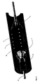
- FIG 1 shows a catheter based drug delivery device 1 in accordance with one embodiment of the invention.
- the device is insertable into a vasculature via a guide wire (as shown in Figure 2 ), includes micro-needles 2 that have two positions, a retracted position and an extended position.
- These needles 2 are mounted on the surface of a balloon catheter 4 and connected via flexible tubing 6 to a multi-lumen supply hose 8.
- the needles/micro-needles or stems (for directly injecting medicine(s)) attached to hollow needle base reservoirs 12.
- the needle stems 10 project outward from the reservoir 12 and are protected within a rubber sleeve or sheath 14.
- the needles 2 Upon inflation of the balloon 4 the needles 2 move outwards (in the radial direction), and stretching and compressing of the protective sheath 14 occurs, which in turn acts to expose the needles 2.
- the needles 2 when exposed can become embedded in the wall of the body cavity. Drugs may be delivered locally, for example to the diseased vessel wall, when the balloon 4 is inflated and subsequently when the needles 2 are embedded in the body cavity such as an artery wall.
- balloon deflation occurs the needles 2 retract under the canopy of the sheath 14.
- the deflated assembly can now be safely removed from the body via a guide wire 16. During this procedure, the needles 2 are concealed and will not cause damage to the endothelium upon insertion and removal of the device.
- the inner diameter of the elasticised sheath 14 is dimensioned so as to be smaller than the outer diameter of a balloon catheter 4 in its collapsed state. This ensures a tight fit between the sheath and balloon at all times when the sheath is loaded on the balloon.
- the sheath must therefore be stretch-fitted onto the balloon catheter.
- the elastic nature of the sheath ensures that the sheath will exert a compressive force on the balloon at all times.
- the balloon is thus maintained in its deflated state at all times except when a greater opposite force is exerted on the sheath by the balloon under the influence of air/fluid introduced under pressure into the balloon to inflate it.
- the expandable member will generally have a collapsed configuration where there is substantially no air or other inflating fluid in the balloon.
- the balloon will also be in a folded configuration when collapsed.
- the compressive force of the sheath acts on the balloon in its folded configuration. The sheath acts to bias the balloon toward its folded configuration.
- the sheath When the balloon is inflated, it is desirable that the sheath causes a tight seal between the needles and the artery wall allowing leak-free delivery. This seal may be achieved by selecting a soft material for the sheath such as a silicone material. Other suitable materials for the sheath include polyurethane.
- the protective foam-rubber cover or sheath 14 is shown in Figure 2 .
- the selected material is both flexible and compressible enough to allow the needle stems 2 to expose upon balloon deployment, but more importantly provides and aids timely retraction and protection of the needle stems when balloon deflation occurs. This is particularly important for safe insertion and timely removal of the device.
- Figures 3 and 4 depict sectional schematics of the device during operation and in-vivo, within a partially occluded vascular cavity 24.
- a plaque 26 is shown to have occurred locally around the inner cavity wall 28 causing partial occlusion.
- the device is shown placed in situ.
- Arrows 27 represent the balloon deployment force while arrows 29 represent the reaction force of the compressing sleeve.
- Figures 3 and 4 illustrate one of the key features of the device which is shown in operation during mid and post deployment.
- the balloon pressure 27 causes the micro-needles 2 to move outward in the radial direction. Due to the compressive force and the circumferential stretch the protective sheath 14 is compressed (generally compression of the sheath will be due to the Poisson effect) thus exposing the micro-needle stems 10 allowing drug delivery (indicated by lines 25) directly into the plaque 26 on the cavity wall 28.
- FIG. 5 depicts three embodiments of devices in accordance with the invention, labeled A-C.
- Embodiment A is a particularly flexible embodiment based on a modular design where the sheath 14 is provided with a plurality of rings 30 of material. These rings 30 may be completely separate from one another or may be connected by one or more interconnecting links.
- Embodiment B has a short balloon 4, and the sheath 14 comprises treatment implements 2 adjacent the balloon's leading end. This embodiment is most suitable to treating chronic total occlusions, as therapeutic delivery will occur as close as is possible to the blockage.
- Embodiment C is a proximal and distal restenosis module suitable for attachment to a stent-loaded catheter.
- a stent 70 is shown in situ around the central portion of the balloon 4, between the sheath rings 30 which are confined to either end of the balloon 4.
- This module has the capability to deliver therapeutic agents to the artery wall immediately distal, proximal or both, of the area where a stent is being implanted, this would remove or reduce the risk of edge restenosis.
- FIG. 6 shows a retrofit sheath 32 according to one embodiment of the invention.
- the sheath is a two part sheath comprising an inner 34 and outer sheath 36.
- the inner sheath 34 has concave reservoirs 38 in (for example molded into) its outer surface 40, while the outer sheath 36 has small holes 39 defined within it to allow the needles sit within.
- a needle/plate assembly 42 sits beneath the outer sheath 36.
- the height h of the outer sheath 36 is greater than the height H of the needles 44.
- the therapeutic solution is stored within the sheath in the concave cavities/reservoirs.
- the balloon is dilated.
- the sheath is stretched and the cavities within the sheath reduce in volume. This decrease in volume causes the therapeutic solution to be expelled from the reservoir and delivered to the site of disease.
- Figure 7 shows the retrofit sheath of Figure 6 loaded onto a balloon catheter, the balloon catheter in its expanded configuration.
- Figure 8 shows the same arrangement with the catheter in its retracted configuration.
- FIGS 9a-9c show a retrofit cutting sheath 48 wherein the treatment implements are blades 50, which may be microsurgical scalpels.
- the scalpels are initially concealed from the artery wall by the external contours of the sheath 48, this allows the catheter to be navigated to the diseased portion of an artery without damaging the healthy vessel wall. It is the protruberances or bumps 51 in the sheath 48 as shown in Figure 9 , which allow the blades 50 to be concealed from the artery wall, prior to and after use.
- the sheath or sleeve 50 can be adapted to be retrofitted to any balloon catheter.
- the sheath 48 is made of an elastic material and it will be appreciated that concealment of implements 50 is achieved because of the elastic properties of the sleeve 48.
- the holes 52 in the sheath will allow exposure of the blades 50 upon dilation of the balloon and deformation of the sheath; this is shown in the final schematic of Figure 9 .
- Radiopaque markers could be added to the sheath to aid placement during the procedure (balloon angioplasty procedure).
Landscapes
- Health & Medical Sciences (AREA)
- Life Sciences & Earth Sciences (AREA)
- Biomedical Technology (AREA)
- Engineering & Computer Science (AREA)
- Animal Behavior & Ethology (AREA)
- General Health & Medical Sciences (AREA)
- Veterinary Medicine (AREA)
- Heart & Thoracic Surgery (AREA)
- Public Health (AREA)
- Surgery (AREA)
- Vascular Medicine (AREA)
- Molecular Biology (AREA)
- Medical Informatics (AREA)
- Nuclear Medicine, Radiotherapy & Molecular Imaging (AREA)
- Cardiology (AREA)
- Oral & Maxillofacial Surgery (AREA)
- Transplantation (AREA)
- Media Introduction/Drainage Providing Device (AREA)
- Surgical Instruments (AREA)
- Infusion, Injection, And Reservoir Apparatuses (AREA)
- Materials For Medical Uses (AREA)
Claims (18)
- Dispositif (1) pour le traitement d'une zone cible d'une paroi vasculaire d'un vaisseau dans un corps humain ou animal, le dispositif comprenant :a) une partie extensible (4) pour étendre radialement le dispositif à partir d'une configuration contractée, permettant le déplacement dans le vaisseau vers une zone cible, vers une configuration étendue permettant le traitement de la zone cible ;b) au moins deux outils de traitement espacés entre eux (2, 50) s'étendant radialement vers l'extérieur à partir de la partie extensible ;c) une gaine de protection (14) ;dans lequel dans la configuration contractée du dispositif les outils sont protégés dans la gaine de protection, et dans sa configuration étendue l'épaisseur de la gaine diminue pour exposer les outils pour un contact avec la zone cible de la paroi vasculaire.
et caractérisé en ce que :la gaine de protection (14) est apte à être montée par étirement sur la partie extensible pour exercer une force de compression sur la partie extensible pour contracter radialement le dispositif à partir de sa configuration étendue vers sa configuration contractée, et pour exercer une force de compression sur la partie extensible dans sa configuration contractée ; - Dispositif selon la revendication 1, dans lequel la partie extensible est un ballonnet.
- Dispositif selon la revendication 1 ou 2, dans lequel les outils de traitement sont des lames (50).
- Dispositif selon l'une quelconque des revendications précédentes, dans lequel les outils de traitement sont des aiguilles (2).
- Dispositif selon la revendication 4, comprenant en outre un système d'alimentation en communication de fluide avec les aiguilles pour fournir un composé thérapeutique par l'intermédiaire des aiguilles dans une paroi vasculaire.
- Dispositif selon la revendication 5, dans lequel le système d'alimentation en médicament comprend une pluralité de réservoirs (12) dans la gaine protectrice.
- Dispositif selon la revendication 5, dans lequel le système d'alimentation en médicament comprend un tuyau d'alimentation (8) connecté par l'intermédiaire d'un tubage (22) aux aiguilles (2).
- Dispositif selon l'une quelconque des revendications précédentes, dans lequel la gaine de protection comprend un polymère élastique.
- Dispositif selon la revendication 8, dans lequel le polymère élastique comprend du silicone.
- Dispositif selon l'une quelconque des revendications précédentes, dans lequel une pluralité de trous est définie dans la gaine de protection, dans lesquels sont placés les outils de traitement.
- Dispositif selon l'une quelconque des revendications précédentes, comprenant en outre au moins un marqueur pour aider au positionnement du dispositif.
- Gaine (32, 48) destinée à être montée sur un cathéter à ballonnet pour le traitement d'une zone cible d'une paroi vasculaire d'un vaisseau dans un corps humain ou animal, la gaine étant apte à être montée par étirement sur le ballonnet pour exercer une force de compression sur le ballonnet pour contracter radialement le ballonnet à partir de sa configuration étendue vers sa configuration contractée, la gaine comprenant :au moins deux outils de traitement espacés entre eux (42, 50), la gaine étant caractérisée en ce que lesdits au moins deux outils de traitement espacés entre eux (42, 50) sont montés dans la gaine de façon à s'étendre radialement vers l'extérieur à partir du ballonnet, et en ce que, dans la configuration contractée du ballonnet, les outils sont protégés dans la gaine, et dans sa configuration étendue, l'épaisseur de la gaine diminue pour exposer les outils à un contact avec la zone cible de la paroi vasculaire.
- Gaine selon la revendication 12, dans laquelle les outils de traitement sont des aiguilles (42).
- Gaine selon la revendication 13, comprenant en outre :une gaine intérieure (34) comprenant une surface extérieure (40) sur laquelle sont prévus une pluralité de réservoirs (38) pour stocker un composé thérapeutique ;une gaine extérieure (36) disposée sur la gaine intérieure (34) ;dans laquelle chacune des aiguilles (42) comprend une partie de base (46) et une partie d'injecteur (44), et dans laquelle chaque partie de base est disposée sur un réservoir sur la surface extérieure de la gaine intérieure, et dans laquelle chaque partie d'injecteur s'étend radialement vers l'extérieur à partir de la gaine intérieure et est reçue dans des trous coopératifs (39) définis dans la gaine extérieure.
- Gaine selon la revendication 12, dans laquelle les outils de traitement sont des outils de coupe (50).
- Gaine selon la revendication 13, comprenant au moins une protubérance (51) sur sa surface extérieure, dans laquelle, dans la configuration contractée du ballonnet, chaque protubérance s'étend radialement vers l'extérieur de la surface externe de la gaine plus loin que chaque outil de coupe.
- Gaine selon la revendication 16, dans laquelle chaque protubérance est escamotable.
- Gaine selon la revendication 16 ou 17, dans laquelle chaque protubérance comporte une poche creuse interne,
dans laquelle, dans la configuration étendue du ballonnet, la déformation de la gaine fait que la poche s'aplatit, réduisant ainsi la dimension de la protubérance dans la direction radiale pour exposer chaque outil de coupe.
Priority Applications (13)
| Application Number | Priority Date | Filing Date | Title |
|---|---|---|---|
| AT06003797T ATE447370T1 (de) | 2006-02-24 | 2006-02-24 | Minimalinvasive intravaskuläre behandlungsvorrichtung |
| DE602006010171T DE602006010171D1 (de) | 2006-02-24 | 2006-02-24 | Minimalinvasive intravaskuläre Behandlungsvorrichtung |
| ES06003797T ES2335520T3 (es) | 2006-02-24 | 2006-02-24 | Dispositivo de tratamiento intravascular minimamente invasivo. |
| EP06003797A EP1825824B1 (fr) | 2006-02-24 | 2006-02-24 | Dispositif de traitement intravasculaire à invasion minimale |
| AT07706010T ATE509584T1 (de) | 2006-02-24 | 2007-02-23 | Minimal invasive intravaskuläre behandlungsvorrichtung |
| PCT/IE2007/000028 WO2007096856A2 (fr) | 2006-02-24 | 2007-02-23 | Dispositif de traitement intravasculaire mini-invasif |
| CN2007800134659A CN101420913B (zh) | 2006-02-24 | 2007-02-23 | 最小侵扰的血管内治疗设备 |
| US11/710,266 US20070213761A1 (en) | 2006-02-24 | 2007-02-23 | Minimally invasive intravascular treatment device |
| EP07706010A EP1996088B1 (fr) | 2006-02-24 | 2007-02-23 | Dispositif de traitement intravasculaire à invasion minimale |
| JP2008555936A JP2009527316A (ja) | 2006-02-24 | 2007-02-23 | 最小侵襲性血管内治療装置 |
| CA002642471A CA2642471A1 (fr) | 2006-02-24 | 2007-02-23 | Dispositif de traitement intravasculaire mini-invasif |
| US11/846,935 US20080077165A1 (en) | 2006-02-24 | 2007-08-29 | Minimally Invasive Intravascular Treatment Device |
| US11/846,887 US20080077164A1 (en) | 2006-02-24 | 2007-08-29 | Minimally Invasive Intravascular Treatment Device |
Applications Claiming Priority (1)
| Application Number | Priority Date | Filing Date | Title |
|---|---|---|---|
| EP06003797A EP1825824B1 (fr) | 2006-02-24 | 2006-02-24 | Dispositif de traitement intravasculaire à invasion minimale |
Publications (2)
| Publication Number | Publication Date |
|---|---|
| EP1825824A1 EP1825824A1 (fr) | 2007-08-29 |
| EP1825824B1 true EP1825824B1 (fr) | 2009-11-04 |
Family
ID=36636615
Family Applications (2)
| Application Number | Title | Priority Date | Filing Date |
|---|---|---|---|
| EP06003797A Expired - Lifetime EP1825824B1 (fr) | 2006-02-24 | 2006-02-24 | Dispositif de traitement intravasculaire à invasion minimale |
| EP07706010A Not-in-force EP1996088B1 (fr) | 2006-02-24 | 2007-02-23 | Dispositif de traitement intravasculaire à invasion minimale |
Family Applications After (1)
| Application Number | Title | Priority Date | Filing Date |
|---|---|---|---|
| EP07706010A Not-in-force EP1996088B1 (fr) | 2006-02-24 | 2007-02-23 | Dispositif de traitement intravasculaire à invasion minimale |
Country Status (9)
| Country | Link |
|---|---|
| US (1) | US20070213761A1 (fr) |
| EP (2) | EP1825824B1 (fr) |
| JP (1) | JP2009527316A (fr) |
| CN (1) | CN101420913B (fr) |
| AT (2) | ATE447370T1 (fr) |
| CA (1) | CA2642471A1 (fr) |
| DE (1) | DE602006010171D1 (fr) |
| ES (1) | ES2335520T3 (fr) |
| WO (1) | WO2007096856A2 (fr) |
Cited By (3)
| Publication number | Priority date | Publication date | Assignee | Title |
|---|---|---|---|---|
| US11071847B1 (en) | 2019-12-24 | 2021-07-27 | Encompass Vascular, Inc. | Medical devices for fluid delivery |
| US11654268B2 (en) | 2021-02-23 | 2023-05-23 | Encompass Vascular, Inc. | Medical devices for fluid delivery and methods of use and manufacture |
| US11759550B2 (en) | 2021-04-30 | 2023-09-19 | Encompass Vascular, Inc. | Medical devices for fluid delivery and methods of use and manufacture |
Families Citing this family (105)
| Publication number | Priority date | Publication date | Assignee | Title |
|---|---|---|---|---|
| US20080077164A1 (en) * | 2006-02-24 | 2008-03-27 | National University Of Ireland, Galway | Minimally Invasive Intravascular Treatment Device |
| US20080077165A1 (en) * | 2006-02-24 | 2008-03-27 | National University Of Ireland, Galway | Minimally Invasive Intravascular Treatment Device |
| DE102007040868A1 (de) * | 2007-08-29 | 2009-04-16 | Innora Gmbh | Ballonkatheter mit Schutz vor Auffaltung |
| US8579956B2 (en) * | 2007-09-28 | 2013-11-12 | Abbott Cardiovascular Systems Inc. | Methods and devices for treating lesions |
| US8043257B2 (en) * | 2007-12-06 | 2011-10-25 | Abbott Cardiovascular Systems Inc. | Agent delivery catheter having an inflation bridge between two axially spaced balloons |
| US9480826B2 (en) * | 2008-03-21 | 2016-11-01 | Cagent Vascular, Llc | Intravascular device |
| US11219750B2 (en) | 2008-03-21 | 2022-01-11 | Cagent Vascular, Inc. | System and method for plaque serration |
| JP5846905B2 (ja) | 2008-03-21 | 2016-01-20 | ケイジェント ヴァスキュラー, エルエルシーCagent Vascular, Llc | 血管内でのアテローム斑の穿孔およびセレーションのための血管内装置 |
| DE102008021066A1 (de) * | 2008-04-26 | 2009-10-29 | Biotronik Vi Patent Ag | Stentbefestigungssystem |
| US8932326B2 (en) * | 2008-06-10 | 2015-01-13 | Cornell University | Method and apparatus for repairing vascular abnormalities and/or other body lumen abnormalities using an endoluminal approach and a flowable forming material |
| WO2010021779A1 (fr) * | 2008-08-21 | 2010-02-25 | Cornell University | Procédé et appareil d'accès à la paroi d'une structure vasculaire ou d’une autre lumière corporelle fournissant simultanément une isolation de la zone et une capacité de dérivation de fluide |
| US8357118B2 (en) | 2008-08-26 | 2013-01-22 | Cook Medical Technologies Llc | Balloon catheters having a plurality of needles for the injection of one or more therapeutic agents |
| EP2194278A1 (fr) * | 2008-12-05 | 2010-06-09 | ECP Entwicklungsgesellschaft mbH | Pompe à fluide dotée d'un rotor |
| US8975233B2 (en) | 2010-01-26 | 2015-03-10 | Northwind Medical, Inc. | Methods for renal denervation |
| US8551130B2 (en) * | 2010-02-18 | 2013-10-08 | Cardiovascular Systems, Inc. | Therapeutic agent delivery system, device and method for localized application of therapeutic substances to a biological conduit |
| EP2407186A1 (fr) | 2010-07-15 | 2012-01-18 | ECP Entwicklungsgesellschaft mbH | Rotor pour une pompe, fabriquée à l'aide d'une matière première élastique |
| WO2012038959A2 (fr) * | 2010-09-21 | 2012-03-29 | Israel Shamir Lebovitz | Aiguille multi-directionnelle |
| CA2817552C (fr) * | 2010-11-16 | 2020-03-24 | Tva Medical, Inc. | Dispositifs et procedes de formation d'une fistule |
| US9839540B2 (en) | 2011-01-14 | 2017-12-12 | W. L. Gore & Associates, Inc. | Stent |
| US10166128B2 (en) | 2011-01-14 | 2019-01-01 | W. L. Gore & Associates. Inc. | Lattice |
| WO2012151257A1 (fr) | 2011-05-05 | 2012-11-08 | Boston Scientific Scimed, Inc. | Dispositif d'administration de médicament pourvu d'une gaine destinée à améliorer l'administration du médicament |
| US8702651B2 (en) | 2011-06-07 | 2014-04-22 | Boston Scientific Scimed, Inc. | Drug delivery device with instable sheath and/or push element |
| EP2741694B1 (fr) * | 2011-08-11 | 2017-02-15 | Boston Scientific Scimed, Inc. | Échafaudage expansible équipé d'éléments de coupe montés sur celui-ci |
| EP2822635B8 (fr) * | 2012-03-09 | 2018-11-14 | Clearstream Technologies Limited | Ballonnet médical comprenant un identificateur radiopaque pour identifier avec précision la surface de travail |
| US9445897B2 (en) | 2012-05-01 | 2016-09-20 | Direct Flow Medical, Inc. | Prosthetic implant delivery device with introducer catheter |
| US9283072B2 (en) | 2012-07-25 | 2016-03-15 | W. L. Gore & Associates, Inc. | Everting transcatheter valve and methods |
| US10376360B2 (en) | 2012-07-27 | 2019-08-13 | W. L. Gore & Associates, Inc. | Multi-frame prosthetic valve apparatus and methods |
| US9931193B2 (en) | 2012-11-13 | 2018-04-03 | W. L. Gore & Associates, Inc. | Elastic stent graft |
| US9101469B2 (en) | 2012-12-19 | 2015-08-11 | W. L. Gore & Associates, Inc. | Prosthetic heart valve with leaflet shelving |
| US9737398B2 (en) | 2012-12-19 | 2017-08-22 | W. L. Gore & Associates, Inc. | Prosthetic valves, frames and leaflets and methods thereof |
| US10279084B2 (en) * | 2012-12-19 | 2019-05-07 | W. L. Gore & Associates, Inc. | Medical balloon devices and methods |
| US10321986B2 (en) | 2012-12-19 | 2019-06-18 | W. L. Gore & Associates, Inc. | Multi-frame prosthetic heart valve |
| US9968443B2 (en) | 2012-12-19 | 2018-05-15 | W. L. Gore & Associates, Inc. | Vertical coaptation zone in a planar portion of prosthetic heart valve leaflet |
| US10966820B2 (en) | 2012-12-19 | 2021-04-06 | W. L. Gore & Associates, Inc. | Geometric control of bending character in prosthetic heart valve leaflets |
| US9144492B2 (en) | 2012-12-19 | 2015-09-29 | W. L. Gore & Associates, Inc. | Truncated leaflet for prosthetic heart valves, preformed valve |
| AU2014232323B2 (en) * | 2013-03-15 | 2019-02-14 | Artio Medical, Inc. | Expandable body device and method of use |
| CN103341231B (zh) * | 2013-07-17 | 2016-04-06 | 成都睿杰森生物科技有限公司 | 可视化腔内组织的给药装置及其方法 |
| US10842918B2 (en) | 2013-12-05 | 2020-11-24 | W.L. Gore & Associates, Inc. | Length extensible implantable device and methods for making such devices |
| EP3132822B1 (fr) * | 2014-04-14 | 2018-10-31 | Toppan Printing Co., Ltd. | Dispositif d'injection |
| WO2015187872A1 (fr) | 2014-06-04 | 2015-12-10 | Cagent Vascular, Llc | Cage pour ballonnet médical |
| EP4736932A2 (fr) * | 2014-07-04 | 2026-05-06 | Abiomed Europe GmbH | Gaine pour l'accès étanche à un vaisseau |
| US9827094B2 (en) | 2014-09-15 | 2017-11-28 | W. L. Gore & Associates, Inc. | Prosthetic heart valve with retention elements |
| AU2015343272B2 (en) | 2014-11-03 | 2020-07-16 | Cagent Vascular, Inc. | Serration balloon |
| KR101663805B1 (ko) * | 2014-12-03 | 2016-10-14 | 연세대학교 산학협력단 | 마이크로 니들이 형성된 풍선도관 및 그 제작방법 |
| JP6815998B2 (ja) | 2014-12-03 | 2021-01-20 | パブメド インク. | 繊維構造の経皮分裂のためのシステム及び方法 |
| JP6367730B2 (ja) * | 2015-02-12 | 2018-08-01 | 株式会社ダイセル | 無針注射装置 |
| ES2802244T3 (es) | 2015-04-10 | 2021-01-18 | Goodman Co Ltd | Catéter balón |
| CN113907834A (zh) | 2015-09-17 | 2022-01-11 | 开金血管公司 | 医用气囊的楔形切割器 |
| JP7145757B2 (ja) * | 2015-10-12 | 2022-10-03 | リフロー メディカル インコーポレイテッド | 突出する薬剤送達フィーチャーを有するステント、ならびに、関連のシステムおよび方法 |
| JP7248430B2 (ja) | 2016-04-21 | 2023-03-29 | ダブリュ.エル.ゴア アンド アソシエイツ,インコーポレイティド | 直径を調節可能な内部人工器官ならびに関連したシステムおよび方法 |
| CN106551737B (zh) * | 2016-11-09 | 2019-01-04 | 恩脉(上海)医疗科技有限公司 | 一种可在体内解体的载药器械保护套 |
| JP7441043B2 (ja) | 2016-11-16 | 2024-02-29 | ケイジェント ヴァスキュラー, インコーポレイテッド | セレーションを介して組織内に薬剤を挿入するシステム及び方法 |
| WO2018176064A2 (fr) | 2017-03-24 | 2018-09-27 | Metactive Medical, Inc. | Dispositifs médicaux comprenant des ballonnets détachables et procédés de fabrication et d'utilisation |
| GB201707929D0 (en) * | 2017-05-17 | 2017-06-28 | Vascutek Ltd | Tubular medical device |
| EP3681440A1 (fr) | 2017-09-12 | 2020-07-22 | W. L. Gore & Associates, Inc. | Fixation de cadre de feuillet pour valves prothétiques |
| JP6875601B2 (ja) | 2017-09-27 | 2021-05-26 | ダブリュ.エル.ゴア アンド アソシエイツ,インコーポレイティドW.L. Gore & Associates, Incorporated | リーフレットが機械的にカップリングされた人工弁 |
| EP3687451B1 (fr) | 2017-09-27 | 2023-12-13 | Edwards Lifesciences Corporation | Valvule prothétique à cadre extensible |
| JP7136901B2 (ja) | 2017-10-09 | 2022-09-13 | ダブリュ.エル.ゴア アンド アソシエイツ,インコーポレイティド | 調和されたステントカバー |
| CA3078699C (fr) | 2017-10-13 | 2023-10-10 | W.L. Gore & Associates, Inc. | Valvule prothetique telescopique et systeme de pose |
| EP3703618A1 (fr) | 2017-10-31 | 2020-09-09 | W. L. Gore & Associates, Inc. | Valve cardiaque prothétique |
| JP7072062B2 (ja) | 2017-10-31 | 2022-05-19 | ダブリュ.エル.ゴア アンド アソシエイツ,インコーポレイティド | 経カテーテル留置システム及び関連する方法 |
| US11439502B2 (en) | 2017-10-31 | 2022-09-13 | W. L. Gore & Associates, Inc. | Medical valve and leaflet promoting tissue ingrowth |
| US10820921B2 (en) * | 2017-12-30 | 2020-11-03 | C.R. Bard, Inc. | Dual access incising catheter |
| WO2019195860A2 (fr) | 2018-04-04 | 2019-10-10 | Vdyne, Llc | Dispositifs et procédés d'ancrage d'une valvule cardiaque transcathéter |
| JP7545381B2 (ja) | 2018-07-25 | 2024-09-04 | ケイジェント ヴァスキュラー, インコーポレイテッド | 押動性能が向上した医療用バルーンカテーテル |
| US12186187B2 (en) | 2018-09-20 | 2025-01-07 | Vdyne, Inc. | Transcatheter deliverable prosthetic heart valves and methods of delivery |
| US10321995B1 (en) | 2018-09-20 | 2019-06-18 | Vdyne, Llc | Orthogonally delivered transcatheter heart valve replacement |
| US11278437B2 (en) | 2018-12-08 | 2022-03-22 | Vdyne, Inc. | Compression capable annular frames for side delivery of transcatheter heart valve replacement |
| US11344413B2 (en) | 2018-09-20 | 2022-05-31 | Vdyne, Inc. | Transcatheter deliverable prosthetic heart valves and methods of delivery |
| US10595994B1 (en) | 2018-09-20 | 2020-03-24 | Vdyne, Llc | Side-delivered transcatheter heart valve replacement |
| US11071627B2 (en) | 2018-10-18 | 2021-07-27 | Vdyne, Inc. | Orthogonally delivered transcatheter heart valve frame for valve in valve prosthesis |
| US11090467B2 (en) | 2018-10-02 | 2021-08-17 | Alucent Biomedical, Inc. | Apparatus and methods for scaffolding |
| US11109969B2 (en) | 2018-10-22 | 2021-09-07 | Vdyne, Inc. | Guidewire delivery of transcatheter heart valve |
| KR102047610B1 (ko) * | 2018-12-18 | 2019-11-22 | 이민우 | 다수의 소형 주사기 또는 주사부를 갖는 마이크로 니들 장치 |
| US11253359B2 (en) | 2018-12-20 | 2022-02-22 | Vdyne, Inc. | Proximal tab for side-delivered transcatheter heart valves and methods of delivery |
| WO2020146842A1 (fr) | 2019-01-10 | 2020-07-16 | Vdyne, Llc | Crochet d'ancrage pour prothèse de valvule cardiaque transcathéter à distribution latérale |
| US11273032B2 (en) | 2019-01-26 | 2022-03-15 | Vdyne, Inc. | Collapsible inner flow control component for side-deliverable transcatheter heart valve prosthesis |
| US11185409B2 (en) | 2019-01-26 | 2021-11-30 | Vdyne, Inc. | Collapsible inner flow control component for side-delivered transcatheter heart valve prosthesis |
| US11497601B2 (en) | 2019-03-01 | 2022-11-15 | W. L. Gore & Associates, Inc. | Telescoping prosthetic valve with retention element |
| CN113543750B (zh) | 2019-03-05 | 2025-10-10 | 维迪内股份有限公司 | 用于正交经导管心脏瓣膜假体的三尖瓣反流控制装置 |
| US11173027B2 (en) | 2019-03-14 | 2021-11-16 | Vdyne, Inc. | Side-deliverable transcatheter prosthetic valves and methods for delivering and anchoring the same |
| US11076956B2 (en) | 2019-03-14 | 2021-08-03 | Vdyne, Inc. | Proximal, distal, and anterior anchoring tabs for side-delivered transcatheter mitral valve prosthesis |
| EP3952790A1 (fr) | 2019-04-12 | 2022-02-16 | W.L. Gore & Associates, Inc. | Valve avec cadre à parties multiples et éléments de pontage élastiques associés |
| AU2020267390B2 (en) | 2019-05-04 | 2025-12-04 | Vdyne, Inc. | Cinch device and method for deployment of a side-delivered prosthetic heart valve in a native annulus |
| BR112021022294A2 (pt) * | 2019-05-07 | 2021-12-28 | Nu Life Consulting Pte Ltd | Estrutura de mola tubular, estrutura de cateter de balão de fragmentação e cateter de balão de fragmentação flexível |
| CN110327538A (zh) * | 2019-08-12 | 2019-10-15 | 肖平喜 | 一种狼牙棒式扩张给药球囊 |
| JP7584500B2 (ja) | 2019-08-20 | 2024-11-15 | ブイダイン,インコーポレイテッド | 側方送達可能な経カテーテル人工弁の送達及び回収のデバイス及び方法 |
| CN114630665B (zh) | 2019-08-26 | 2025-06-17 | 维迪内股份有限公司 | 可侧面输送的经导管假体瓣膜及其输送和锚定方法 |
| CN110507385B (zh) * | 2019-09-04 | 2021-02-19 | 肖平喜 | 一种镶嵌式扩张球囊 |
| AU2020397886A1 (en) * | 2019-12-03 | 2022-06-16 | Boston Scientific Scimed, Inc. | Medical delivery device |
| EP4076230B1 (fr) | 2019-12-20 | 2024-10-16 | SurModics, Inc. | Dispositif de gravure universel |
| CN111228640A (zh) * | 2020-01-10 | 2020-06-05 | 李雷 | 脉管封闭装置 |
| US11234813B2 (en) | 2020-01-17 | 2022-02-01 | Vdyne, Inc. | Ventricular stability elements for side-deliverable prosthetic heart valves and methods of delivery |
| US12011184B2 (en) | 2020-02-10 | 2024-06-18 | Elixir Medical Corporation | Methods and apparatus for plaque disruption |
| CN111420248A (zh) * | 2020-04-09 | 2020-07-17 | 玮铭医疗器械(上海)有限公司 | 一种弹性球囊回复装置 |
| US12156693B2 (en) | 2020-05-27 | 2024-12-03 | PAVmed Inc. | Systems and methods for minimally-invasive division of fibrous structures |
| CN114469322B (zh) * | 2022-01-25 | 2022-08-23 | 广东博迈医疗科技股份有限公司 | 一种切割执行机构及切割球囊导管 |
| EP4590213A2 (fr) * | 2022-09-23 | 2025-07-30 | Elixir Medical Corporation | Procédés et appareil de rupture de plaque |
| EP4601585A1 (fr) | 2022-10-14 | 2025-08-20 | Vdyne, Inc. | Dispositifs et procédés de pose d'une valve cardiaque prothétique à l'aide d'un support supra-annulaire |
| JP2024116707A (ja) * | 2023-02-16 | 2024-08-28 | 株式会社東海メディカルプロダクツ | バルーン及びバルーンカテーテル |
| CN115813629B (zh) * | 2023-02-22 | 2023-07-21 | 北京泰杰伟业科技股份有限公司 | 破口球囊 |
| CN116328159B (zh) * | 2023-04-10 | 2025-12-05 | 苏州天鸿盛捷医疗器械有限公司 | 一种带有微针的球囊导管及其制备方法 |
| CN116747416B (zh) * | 2023-05-24 | 2024-11-22 | 中国人民解放军总医院第一医学中心 | 一种基于动脉狭窄防治的微针注射扩张装置 |
| CN118078382B (zh) * | 2024-04-26 | 2024-06-21 | 鼎科医疗技术(苏州)有限公司 | 一种载药刻痕球囊及球囊导管 |
| CN120714150B (zh) * | 2025-08-14 | 2025-12-30 | 鼎科医疗技术(苏州)有限公司 | 一种乳突球囊及球囊扩张导管 |
Citations (1)
| Publication number | Priority date | Publication date | Assignee | Title |
|---|---|---|---|---|
| WO2004096097A2 (fr) * | 2003-04-25 | 2004-11-11 | Boston Scientific Limited | Tuteur et ballonnet de coupe |
Family Cites Families (31)
| Publication number | Priority date | Publication date | Assignee | Title |
|---|---|---|---|---|
| US5242397A (en) * | 1989-06-20 | 1993-09-07 | Cedars-Sinai Medical Center | Catheter device and method of use for intramural delivery of protein kinase C and tyrosine protein kinase inhibitors to prevent restenosis after balloon angioplasty |
| HU212760B (en) * | 1989-06-20 | 1997-02-28 | Denes | Method and device for the apportion of chemical materials into the vein wall |
| US5196024A (en) * | 1990-07-03 | 1993-03-23 | Cedars-Sinai Medical Center | Balloon catheter with cutting edge |
| CA2074304C (fr) * | 1991-08-02 | 1996-11-26 | Cyril J. Schweich, Jr. | Catheter pour l'administration de medicaments |
| DE4235506A1 (de) * | 1992-10-21 | 1994-04-28 | Bavaria Med Tech | Katheter zur Injektion von Arzneimitteln |
| US5336178A (en) * | 1992-11-02 | 1994-08-09 | Localmed, Inc. | Intravascular catheter with infusion array |
| WO1994023787A1 (fr) * | 1993-04-22 | 1994-10-27 | Rammler David H | Catheter a ballon de prelevement |
| JP3655631B2 (ja) * | 1994-02-07 | 2005-06-02 | 株式会社伊垣医療設計 | ステント装置及びステント供給システム |
| US5873852A (en) * | 1995-07-10 | 1999-02-23 | Interventional Technologies | Device for injecting fluid into a wall of a blood vessel |
| IT1279628B1 (it) * | 1995-09-13 | 1997-12-16 | Xtrode Srl | Dispositivo e metodo per il montaggio di una endoprotesi vascolare su un catetere provvisto di un pallone espandibile |
| US5797935A (en) * | 1996-09-26 | 1998-08-25 | Interventional Technologies Inc. | Balloon activated forced concentrators for incising stenotic segments |
| EP0835673A3 (fr) * | 1996-10-10 | 1998-09-23 | Schneider (Usa) Inc. | Cathéter pour dilatation de tissue et administration de médicaments |
| US6197013B1 (en) * | 1996-11-06 | 2001-03-06 | Setagon, Inc. | Method and apparatus for drug and gene delivery |
| US5713913A (en) * | 1996-11-12 | 1998-02-03 | Interventional Technologies Inc. | Device and method for transecting a coronary artery |
| IT1286780B1 (it) * | 1996-11-20 | 1998-07-17 | Bard Galway Ltd | Dispositivo per montare una endoprotesi tubolare per impianto vascolare su un catetere di trasporto ed espansione |
| US5843027A (en) * | 1996-12-04 | 1998-12-01 | Cardiovascular Dynamics, Inc. | Balloon sheath |
| US6018857A (en) * | 1997-10-30 | 2000-02-01 | Ave Connaught | Device and method for mounting a stent onto a balloon catheter |
| US6369039B1 (en) * | 1998-06-30 | 2002-04-09 | Scimed Life Sytems, Inc. | High efficiency local drug delivery |
| US6280414B1 (en) * | 1998-09-30 | 2001-08-28 | Medtronic Ave, Inc. | Method and apparatus for local delivery of therapeutic agent |
| US6048332A (en) * | 1998-10-09 | 2000-04-11 | Ave Connaught | Dimpled porous infusion balloon |
| US6695830B2 (en) * | 1999-01-15 | 2004-02-24 | Scimed Life Systems, Inc. | Method for delivering medication into an arterial wall for prevention of restenosis |
| US6210392B1 (en) * | 1999-01-15 | 2001-04-03 | Interventional Technologies, Inc. | Method for treating a wall of a blood vessel |
| US6478778B1 (en) * | 1999-05-28 | 2002-11-12 | Precision Vascular Systems, Inc. | Apparatus for delivering fluids to blood vessels, body cavities, and the like |
| US6494862B1 (en) * | 1999-07-13 | 2002-12-17 | Advanced Cardiovascular Systems, Inc. | Substance delivery apparatus and a method of delivering a therapeutic substance to an anatomical passageway |
| US6283947B1 (en) * | 1999-07-13 | 2001-09-04 | Advanced Cardiovascular Systems, Inc. | Local drug delivery injection catheter |
| US6638246B1 (en) * | 2000-11-28 | 2003-10-28 | Scimed Life Systems, Inc. | Medical device for delivery of a biologically active material to a lumen |
| US20020161388A1 (en) * | 2001-02-27 | 2002-10-31 | Samuels Sam L. | Elastomeric balloon support fabric |
| US7494497B2 (en) * | 2003-01-02 | 2009-02-24 | Boston Scientific Scimed, Inc. | Medical devices |
| US7008438B2 (en) * | 2003-07-14 | 2006-03-07 | Scimed Life Systems, Inc. | Anchored PTCA balloon |
| US7799043B2 (en) * | 2003-12-01 | 2010-09-21 | Boston Scientific Scimed, Inc. | Cutting balloon having sheathed incising elements |
| US7413558B2 (en) * | 2003-12-19 | 2008-08-19 | Boston Scientific Scimed, Inc. | Elastically distensible folding member |
-
2006
- 2006-02-24 DE DE602006010171T patent/DE602006010171D1/de not_active Expired - Lifetime
- 2006-02-24 EP EP06003797A patent/EP1825824B1/fr not_active Expired - Lifetime
- 2006-02-24 AT AT06003797T patent/ATE447370T1/de not_active IP Right Cessation
- 2006-02-24 ES ES06003797T patent/ES2335520T3/es not_active Expired - Lifetime
-
2007
- 2007-02-23 US US11/710,266 patent/US20070213761A1/en not_active Abandoned
- 2007-02-23 CA CA002642471A patent/CA2642471A1/fr not_active Abandoned
- 2007-02-23 WO PCT/IE2007/000028 patent/WO2007096856A2/fr not_active Ceased
- 2007-02-23 EP EP07706010A patent/EP1996088B1/fr not_active Not-in-force
- 2007-02-23 AT AT07706010T patent/ATE509584T1/de not_active IP Right Cessation
- 2007-02-23 CN CN2007800134659A patent/CN101420913B/zh not_active Expired - Fee Related
- 2007-02-23 JP JP2008555936A patent/JP2009527316A/ja active Pending
Patent Citations (1)
| Publication number | Priority date | Publication date | Assignee | Title |
|---|---|---|---|---|
| WO2004096097A2 (fr) * | 2003-04-25 | 2004-11-11 | Boston Scientific Limited | Tuteur et ballonnet de coupe |
Cited By (9)
| Publication number | Priority date | Publication date | Assignee | Title |
|---|---|---|---|---|
| US11071847B1 (en) | 2019-12-24 | 2021-07-27 | Encompass Vascular, Inc. | Medical devices for fluid delivery |
| US11167111B1 (en) | 2019-12-24 | 2021-11-09 | Encompass Vascular, Inc. | Medical devices for fluid delivery |
| US11491312B2 (en) | 2019-12-24 | 2022-11-08 | Encompass Vascular, Inc. | Medical devices for fluid delivery |
| US12090286B2 (en) | 2019-12-24 | 2024-09-17 | Encompass Vascular, Inc. | Medical devices for fluid delivery |
| US11654268B2 (en) | 2021-02-23 | 2023-05-23 | Encompass Vascular, Inc. | Medical devices for fluid delivery and methods of use and manufacture |
| US11654269B2 (en) | 2021-02-23 | 2023-05-23 | Encompass Vascular, Inc. | Medical devices for fluid delivery and methods of use and manufacture |
| US12226599B2 (en) | 2021-02-23 | 2025-02-18 | Encompass Vascular, Inc. | Medical devices for fluid delivery and methods of use and manufacture |
| US11759550B2 (en) | 2021-04-30 | 2023-09-19 | Encompass Vascular, Inc. | Medical devices for fluid delivery and methods of use and manufacture |
| US11918768B2 (en) | 2021-04-30 | 2024-03-05 | Encompass Vascular, Inc. | Medical devices for fluid delivery and methods of use and manufacture |
Also Published As
| Publication number | Publication date |
|---|---|
| EP1996088A2 (fr) | 2008-12-03 |
| CA2642471A1 (fr) | 2007-08-30 |
| CN101420913B (zh) | 2012-03-21 |
| JP2009527316A (ja) | 2009-07-30 |
| ATE447370T1 (de) | 2009-11-15 |
| WO2007096856A3 (fr) | 2008-01-03 |
| ATE509584T1 (de) | 2011-06-15 |
| EP1825824A1 (fr) | 2007-08-29 |
| US20070213761A1 (en) | 2007-09-13 |
| WO2007096856A2 (fr) | 2007-08-30 |
| CN101420913A (zh) | 2009-04-29 |
| EP1996088B1 (fr) | 2011-05-18 |
| DE602006010171D1 (de) | 2009-12-17 |
| ES2335520T3 (es) | 2010-03-29 |
Similar Documents
| Publication | Publication Date | Title |
|---|---|---|
| EP1825824B1 (fr) | Dispositif de traitement intravasculaire à invasion minimale | |
| US20080077165A1 (en) | Minimally Invasive Intravascular Treatment Device | |
| US20080077164A1 (en) | Minimally Invasive Intravascular Treatment Device | |
| US12268410B2 (en) | Temporary vascular scaffold and scoring device | |
| US9114031B2 (en) | Method for treating a target site in a vascular body channel | |
| US7413558B2 (en) | Elastically distensible folding member | |
| US20190159912A1 (en) | Method and device for treating a target site in a vascular body channel | |
| JP2956966B2 (ja) | カテーテルアセンブリおよびステント供給システム | |
| US20180228537A1 (en) | Medical device comprising a balloon-stent assembly and methods of using the same | |
| JP2016501075A5 (fr) | ||
| CN215822075U (zh) | 一种聚力载药球囊扩张导管 | |
| CN216653092U (zh) | 一种球囊导管系统 | |
| HK1112382A (en) | Minimally invasive intravascular treatment device | |
| US20230285174A1 (en) | Medical device comprising a balloon-stent assembly and methods of using the same |
Legal Events
| Date | Code | Title | Description |
|---|---|---|---|
| PUAI | Public reference made under article 153(3) epc to a published international application that has entered the european phase |
Free format text: ORIGINAL CODE: 0009012 |
|
| AK | Designated contracting states |
Kind code of ref document: A1 Designated state(s): AT BE BG CH CY CZ DE DK EE ES FI FR GB GR HU IE IS IT LI LT LU LV MC NL PL PT RO SE SI SK TR |
|
| AX | Request for extension of the european patent |
Extension state: AL BA HR MK YU |
|
| 17P | Request for examination filed |
Effective date: 20080116 |
|
| 17Q | First examination report despatched |
Effective date: 20080214 |
|
| AKX | Designation fees paid |
Designated state(s): AT BE BG CH CY CZ DE DK EE ES FI FR GB GR HU IE IS IT LI LT LU LV MC NL PL PT RO SE SI SK TR |
|
| REG | Reference to a national code |
Ref country code: HK Ref legal event code: DE Ref document number: 1112382 Country of ref document: HK |
|
| GRAP | Despatch of communication of intention to grant a patent |
Free format text: ORIGINAL CODE: EPIDOSNIGR1 |
|
| GRAS | Grant fee paid |
Free format text: ORIGINAL CODE: EPIDOSNIGR3 |
|
| GRAA | (expected) grant |
Free format text: ORIGINAL CODE: 0009210 |
|
| AK | Designated contracting states |
Kind code of ref document: B1 Designated state(s): AT BE BG CH CY CZ DE DK EE ES FI FR GB GR HU IE IS IT LI LT LU LV MC NL PL PT RO SE SI SK TR |
|
| REG | Reference to a national code |
Ref country code: GB Ref legal event code: FG4D |
|
| REG | Reference to a national code |
Ref country code: CH Ref legal event code: EP |
|
| REG | Reference to a national code |
Ref country code: IE Ref legal event code: FG4D |
|
| REF | Corresponds to: |
Ref document number: 602006010171 Country of ref document: DE Date of ref document: 20091217 Kind code of ref document: P |
|
| REG | Reference to a national code |
Ref country code: ES Ref legal event code: FG2A Ref document number: 2335520 Country of ref document: ES Kind code of ref document: T3 |
|
| LTIE | Lt: invalidation of european patent or patent extension |
Effective date: 20091104 |
|
| PG25 | Lapsed in a contracting state [announced via postgrant information from national office to epo] |
Ref country code: LT Free format text: LAPSE BECAUSE OF FAILURE TO SUBMIT A TRANSLATION OF THE DESCRIPTION OR TO PAY THE FEE WITHIN THE PRESCRIBED TIME-LIMIT Effective date: 20091104 Ref country code: SE Free format text: LAPSE BECAUSE OF FAILURE TO SUBMIT A TRANSLATION OF THE DESCRIPTION OR TO PAY THE FEE WITHIN THE PRESCRIBED TIME-LIMIT Effective date: 20091104 Ref country code: PT Free format text: LAPSE BECAUSE OF FAILURE TO SUBMIT A TRANSLATION OF THE DESCRIPTION OR TO PAY THE FEE WITHIN THE PRESCRIBED TIME-LIMIT Effective date: 20100304 Ref country code: FI Free format text: LAPSE BECAUSE OF FAILURE TO SUBMIT A TRANSLATION OF THE DESCRIPTION OR TO PAY THE FEE WITHIN THE PRESCRIBED TIME-LIMIT Effective date: 20091104 Ref country code: IS Free format text: LAPSE BECAUSE OF FAILURE TO SUBMIT A TRANSLATION OF THE DESCRIPTION OR TO PAY THE FEE WITHIN THE PRESCRIBED TIME-LIMIT Effective date: 20100304 |
|
| PG25 | Lapsed in a contracting state [announced via postgrant information from national office to epo] |
Ref country code: CY Free format text: LAPSE BECAUSE OF FAILURE TO SUBMIT A TRANSLATION OF THE DESCRIPTION OR TO PAY THE FEE WITHIN THE PRESCRIBED TIME-LIMIT Effective date: 20091104 Ref country code: PL Free format text: LAPSE BECAUSE OF FAILURE TO SUBMIT A TRANSLATION OF THE DESCRIPTION OR TO PAY THE FEE WITHIN THE PRESCRIBED TIME-LIMIT Effective date: 20091104 Ref country code: SI Free format text: LAPSE BECAUSE OF FAILURE TO SUBMIT A TRANSLATION OF THE DESCRIPTION OR TO PAY THE FEE WITHIN THE PRESCRIBED TIME-LIMIT Effective date: 20091104 Ref country code: LV Free format text: LAPSE BECAUSE OF FAILURE TO SUBMIT A TRANSLATION OF THE DESCRIPTION OR TO PAY THE FEE WITHIN THE PRESCRIBED TIME-LIMIT Effective date: 20091104 |
|
| PG25 | Lapsed in a contracting state [announced via postgrant information from national office to epo] |
Ref country code: BE Free format text: LAPSE BECAUSE OF FAILURE TO SUBMIT A TRANSLATION OF THE DESCRIPTION OR TO PAY THE FEE WITHIN THE PRESCRIBED TIME-LIMIT Effective date: 20091104 Ref country code: AT Free format text: LAPSE BECAUSE OF FAILURE TO SUBMIT A TRANSLATION OF THE DESCRIPTION OR TO PAY THE FEE WITHIN THE PRESCRIBED TIME-LIMIT Effective date: 20091104 |
|
| PG25 | Lapsed in a contracting state [announced via postgrant information from national office to epo] |
Ref country code: EE Free format text: LAPSE BECAUSE OF FAILURE TO SUBMIT A TRANSLATION OF THE DESCRIPTION OR TO PAY THE FEE WITHIN THE PRESCRIBED TIME-LIMIT Effective date: 20091104 Ref country code: BG Free format text: LAPSE BECAUSE OF FAILURE TO SUBMIT A TRANSLATION OF THE DESCRIPTION OR TO PAY THE FEE WITHIN THE PRESCRIBED TIME-LIMIT Effective date: 20100204 Ref country code: RO Free format text: LAPSE BECAUSE OF FAILURE TO SUBMIT A TRANSLATION OF THE DESCRIPTION OR TO PAY THE FEE WITHIN THE PRESCRIBED TIME-LIMIT Effective date: 20091104 Ref country code: DK Free format text: LAPSE BECAUSE OF FAILURE TO SUBMIT A TRANSLATION OF THE DESCRIPTION OR TO PAY THE FEE WITHIN THE PRESCRIBED TIME-LIMIT Effective date: 20091104 |
|
| PG25 | Lapsed in a contracting state [announced via postgrant information from national office to epo] |
Ref country code: CZ Free format text: LAPSE BECAUSE OF FAILURE TO SUBMIT A TRANSLATION OF THE DESCRIPTION OR TO PAY THE FEE WITHIN THE PRESCRIBED TIME-LIMIT Effective date: 20091104 Ref country code: SK Free format text: LAPSE BECAUSE OF FAILURE TO SUBMIT A TRANSLATION OF THE DESCRIPTION OR TO PAY THE FEE WITHIN THE PRESCRIBED TIME-LIMIT Effective date: 20091104 |
|
| PLBE | No opposition filed within time limit |
Free format text: ORIGINAL CODE: 0009261 |
|
| STAA | Information on the status of an ep patent application or granted ep patent |
Free format text: STATUS: NO OPPOSITION FILED WITHIN TIME LIMIT |
|
| REG | Reference to a national code |
Ref country code: CH Ref legal event code: PL |
|
| 26N | No opposition filed |
Effective date: 20100805 |
|
| PG25 | Lapsed in a contracting state [announced via postgrant information from national office to epo] |
Ref country code: CH Free format text: LAPSE BECAUSE OF NON-PAYMENT OF DUE FEES Effective date: 20100228 Ref country code: MC Free format text: LAPSE BECAUSE OF NON-PAYMENT OF DUE FEES Effective date: 20100301 Ref country code: LI Free format text: LAPSE BECAUSE OF NON-PAYMENT OF DUE FEES Effective date: 20100228 Ref country code: GR Free format text: LAPSE BECAUSE OF FAILURE TO SUBMIT A TRANSLATION OF THE DESCRIPTION OR TO PAY THE FEE WITHIN THE PRESCRIBED TIME-LIMIT Effective date: 20100205 |
|
| PGFP | Annual fee paid to national office [announced via postgrant information from national office to epo] |
Ref country code: FR Payment date: 20120215 Year of fee payment: 7 Ref country code: IE Payment date: 20120210 Year of fee payment: 7 |
|
| PGFP | Annual fee paid to national office [announced via postgrant information from national office to epo] |
Ref country code: DE Payment date: 20120228 Year of fee payment: 7 |
|
| PGFP | Annual fee paid to national office [announced via postgrant information from national office to epo] |
Ref country code: IT Payment date: 20120221 Year of fee payment: 7 Ref country code: GB Payment date: 20120117 Year of fee payment: 7 |
|
| PGFP | Annual fee paid to national office [announced via postgrant information from national office to epo] |
Ref country code: NL Payment date: 20120228 Year of fee payment: 7 |
|
| PG25 | Lapsed in a contracting state [announced via postgrant information from national office to epo] |
Ref country code: LU Free format text: LAPSE BECAUSE OF NON-PAYMENT OF DUE FEES Effective date: 20100224 Ref country code: HU Free format text: LAPSE BECAUSE OF FAILURE TO SUBMIT A TRANSLATION OF THE DESCRIPTION OR TO PAY THE FEE WITHIN THE PRESCRIBED TIME-LIMIT Effective date: 20100505 |
|
| PG25 | Lapsed in a contracting state [announced via postgrant information from national office to epo] |
Ref country code: TR Free format text: LAPSE BECAUSE OF FAILURE TO SUBMIT A TRANSLATION OF THE DESCRIPTION OR TO PAY THE FEE WITHIN THE PRESCRIBED TIME-LIMIT Effective date: 20091104 |
|
| PGFP | Annual fee paid to national office [announced via postgrant information from national office to epo] |
Ref country code: ES Payment date: 20120126 Year of fee payment: 7 |
|
| REG | Reference to a national code |
Ref country code: NL Ref legal event code: V1 Effective date: 20130901 |
|
| GBPC | Gb: european patent ceased through non-payment of renewal fee |
Effective date: 20130224 |
|
| PG25 | Lapsed in a contracting state [announced via postgrant information from national office to epo] |
Ref country code: NL Free format text: LAPSE BECAUSE OF NON-PAYMENT OF DUE FEES Effective date: 20130901 |
|
| REG | Reference to a national code |
Ref country code: FR Ref legal event code: ST Effective date: 20131031 |
|
| REG | Reference to a national code |
Ref country code: IE Ref legal event code: MM4A |
|
| REG | Reference to a national code |
Ref country code: DE Ref legal event code: R119 Ref document number: 602006010171 Country of ref document: DE Effective date: 20130903 |
|
| PG25 | Lapsed in a contracting state [announced via postgrant information from national office to epo] |
Ref country code: IT Free format text: LAPSE BECAUSE OF NON-PAYMENT OF DUE FEES Effective date: 20130224 |
|
| PG25 | Lapsed in a contracting state [announced via postgrant information from national office to epo] |
Ref country code: DE Free format text: LAPSE BECAUSE OF NON-PAYMENT OF DUE FEES Effective date: 20130903 Ref country code: IE Free format text: LAPSE BECAUSE OF NON-PAYMENT OF DUE FEES Effective date: 20130224 Ref country code: FR Free format text: LAPSE BECAUSE OF NON-PAYMENT OF DUE FEES Effective date: 20130228 Ref country code: GB Free format text: LAPSE BECAUSE OF NON-PAYMENT OF DUE FEES Effective date: 20130224 |
|
| REG | Reference to a national code |
Ref country code: ES Ref legal event code: FD2A Effective date: 20140408 |
|
| PG25 | Lapsed in a contracting state [announced via postgrant information from national office to epo] |
Ref country code: ES Free format text: LAPSE BECAUSE OF NON-PAYMENT OF DUE FEES Effective date: 20130225 |
|
| REG | Reference to a national code |
Ref country code: HK Ref legal event code: WD Ref document number: 1112382 Country of ref document: HK |