EP1826363A2 - Protection d'érosion du bord d'attaque d'une vanne en matériau composite - Google Patents
Protection d'érosion du bord d'attaque d'une vanne en matériau composite Download PDFInfo
- Publication number
- EP1826363A2 EP1826363A2 EP07103201A EP07103201A EP1826363A2 EP 1826363 A2 EP1826363 A2 EP 1826363A2 EP 07103201 A EP07103201 A EP 07103201A EP 07103201 A EP07103201 A EP 07103201A EP 1826363 A2 EP1826363 A2 EP 1826363A2
- Authority
- EP
- European Patent Office
- Prior art keywords
- leading edge
- wire mesh
- mesh screen
- engine
- composite stator
- Prior art date
- Legal status (The legal status is an assumption and is not a legal conclusion. Google has not performed a legal analysis and makes no representation as to the accuracy of the status listed.)
- Withdrawn
Links
Images


Classifications
-
- F—MECHANICAL ENGINEERING; LIGHTING; HEATING; WEAPONS; BLASTING
- F01—MACHINES OR ENGINES IN GENERAL; ENGINE PLANTS IN GENERAL; STEAM ENGINES
- F01D—NON-POSITIVE DISPLACEMENT MACHINES OR ENGINES, e.g. STEAM TURBINES
- F01D5/00—Blades; Blade-carrying members; Heating, heat-insulating, cooling or antivibration means on the blades or the members
- F01D5/12—Blades
- F01D5/28—Selecting particular materials; Particular measures relating thereto; Measures against erosion or corrosion
- F01D5/288—Protective coatings for blades
-
- F—MECHANICAL ENGINEERING; LIGHTING; HEATING; WEAPONS; BLASTING
- F01—MACHINES OR ENGINES IN GENERAL; ENGINE PLANTS IN GENERAL; STEAM ENGINES
- F01D—NON-POSITIVE DISPLACEMENT MACHINES OR ENGINES, e.g. STEAM TURBINES
- F01D5/00—Blades; Blade-carrying members; Heating, heat-insulating, cooling or antivibration means on the blades or the members
- F01D5/12—Blades
- F01D5/28—Selecting particular materials; Particular measures relating thereto; Measures against erosion or corrosion
- F01D5/282—Selecting composite materials, e.g. blades with reinforcing filaments
-
- F—MECHANICAL ENGINEERING; LIGHTING; HEATING; WEAPONS; BLASTING
- F01—MACHINES OR ENGINES IN GENERAL; ENGINE PLANTS IN GENERAL; STEAM ENGINES
- F01D—NON-POSITIVE DISPLACEMENT MACHINES OR ENGINES, e.g. STEAM TURBINES
- F01D5/00—Blades; Blade-carrying members; Heating, heat-insulating, cooling or antivibration means on the blades or the members
- F01D5/12—Blades
- F01D5/28—Selecting particular materials; Particular measures relating thereto; Measures against erosion or corrosion
- F01D5/284—Selection of ceramic materials
-
- F—MECHANICAL ENGINEERING; LIGHTING; HEATING; WEAPONS; BLASTING
- F01—MACHINES OR ENGINES IN GENERAL; ENGINE PLANTS IN GENERAL; STEAM ENGINES
- F01D—NON-POSITIVE DISPLACEMENT MACHINES OR ENGINES, e.g. STEAM TURBINES
- F01D5/00—Blades; Blade-carrying members; Heating, heat-insulating, cooling or antivibration means on the blades or the members
- F01D5/12—Blades
- F01D5/28—Selecting particular materials; Particular measures relating thereto; Measures against erosion or corrosion
- F01D5/286—Particular treatment of blades, e.g. to increase durability or resistance against corrosion or erosion
-
- F—MECHANICAL ENGINEERING; LIGHTING; HEATING; WEAPONS; BLASTING
- F05—INDEXING SCHEMES RELATING TO ENGINES OR PUMPS IN VARIOUS SUBCLASSES OF CLASSES F01-F04
- F05C—INDEXING SCHEME RELATING TO MATERIALS, MATERIAL PROPERTIES OR MATERIAL CHARACTERISTICS FOR MACHINES, ENGINES OR PUMPS OTHER THAN NON-POSITIVE-DISPLACEMENT MACHINES OR ENGINES
- F05C2201/00—Metals
- F05C2201/04—Heavy metals
- F05C2201/0433—Iron group; Ferrous alloys, e.g. steel
- F05C2201/0463—Cobalt
-
- F—MECHANICAL ENGINEERING; LIGHTING; HEATING; WEAPONS; BLASTING
- F05—INDEXING SCHEMES RELATING TO ENGINES OR PUMPS IN VARIOUS SUBCLASSES OF CLASSES F01-F04
- F05C—INDEXING SCHEME RELATING TO MATERIALS, MATERIAL PROPERTIES OR MATERIAL CHARACTERISTICS FOR MACHINES, ENGINES OR PUMPS OTHER THAN NON-POSITIVE-DISPLACEMENT MACHINES OR ENGINES
- F05C2201/00—Metals
- F05C2201/04—Heavy metals
- F05C2201/0433—Iron group; Ferrous alloys, e.g. steel
- F05C2201/0466—Nickel
-
- F—MECHANICAL ENGINEERING; LIGHTING; HEATING; WEAPONS; BLASTING
- F05—INDEXING SCHEMES RELATING TO ENGINES OR PUMPS IN VARIOUS SUBCLASSES OF CLASSES F01-F04
- F05D—INDEXING SCHEME FOR ASPECTS RELATING TO NON-POSITIVE-DISPLACEMENT MACHINES OR ENGINES, GAS-TURBINES OR JET-PROPULSION PLANTS
- F05D2300/00—Materials; Properties thereof
- F05D2300/20—Oxide or non-oxide ceramics
- F05D2300/21—Oxide ceramics
-
- F—MECHANICAL ENGINEERING; LIGHTING; HEATING; WEAPONS; BLASTING
- F05—INDEXING SCHEMES RELATING TO ENGINES OR PUMPS IN VARIOUS SUBCLASSES OF CLASSES F01-F04
- F05D—INDEXING SCHEME FOR ASPECTS RELATING TO NON-POSITIVE-DISPLACEMENT MACHINES OR ENGINES, GAS-TURBINES OR JET-PROPULSION PLANTS
- F05D2300/00—Materials; Properties thereof
- F05D2300/20—Oxide or non-oxide ceramics
- F05D2300/22—Non-oxide ceramics
- F05D2300/224—Carbon, e.g. graphite
-
- F—MECHANICAL ENGINEERING; LIGHTING; HEATING; WEAPONS; BLASTING
- F05—INDEXING SCHEMES RELATING TO ENGINES OR PUMPS IN VARIOUS SUBCLASSES OF CLASSES F01-F04
- F05D—INDEXING SCHEME FOR ASPECTS RELATING TO NON-POSITIVE-DISPLACEMENT MACHINES OR ENGINES, GAS-TURBINES OR JET-PROPULSION PLANTS
- F05D2300/00—Materials; Properties thereof
- F05D2300/20—Oxide or non-oxide ceramics
- F05D2300/22—Non-oxide ceramics
- F05D2300/226—Carbides
- F05D2300/2261—Carbides of silicon
-
- F—MECHANICAL ENGINEERING; LIGHTING; HEATING; WEAPONS; BLASTING
- F05—INDEXING SCHEMES RELATING TO ENGINES OR PUMPS IN VARIOUS SUBCLASSES OF CLASSES F01-F04
- F05D—INDEXING SCHEME FOR ASPECTS RELATING TO NON-POSITIVE-DISPLACEMENT MACHINES OR ENGINES, GAS-TURBINES OR JET-PROPULSION PLANTS
- F05D2300/00—Materials; Properties thereof
- F05D2300/20—Oxide or non-oxide ceramics
- F05D2300/22—Non-oxide ceramics
- F05D2300/226—Carbides
- F05D2300/2263—Carbides of tungsten, e.g. WC
-
- F—MECHANICAL ENGINEERING; LIGHTING; HEATING; WEAPONS; BLASTING
- F05—INDEXING SCHEMES RELATING TO ENGINES OR PUMPS IN VARIOUS SUBCLASSES OF CLASSES F01-F04
- F05D—INDEXING SCHEME FOR ASPECTS RELATING TO NON-POSITIVE-DISPLACEMENT MACHINES OR ENGINES, GAS-TURBINES OR JET-PROPULSION PLANTS
- F05D2300/00—Materials; Properties thereof
- F05D2300/40—Organic materials
- F05D2300/43—Synthetic polymers, e.g. plastics; Rubber
- F05D2300/433—Polyamides, e.g. NYLON
-
- F—MECHANICAL ENGINEERING; LIGHTING; HEATING; WEAPONS; BLASTING
- F05—INDEXING SCHEMES RELATING TO ENGINES OR PUMPS IN VARIOUS SUBCLASSES OF CLASSES F01-F04
- F05D—INDEXING SCHEME FOR ASPECTS RELATING TO NON-POSITIVE-DISPLACEMENT MACHINES OR ENGINES, GAS-TURBINES OR JET-PROPULSION PLANTS
- F05D2300/00—Materials; Properties thereof
- F05D2300/60—Properties or characteristics given to material by treatment or manufacturing
- F05D2300/603—Composites; e.g. fibre-reinforced
-
- Y—GENERAL TAGGING OF NEW TECHNOLOGICAL DEVELOPMENTS; GENERAL TAGGING OF CROSS-SECTIONAL TECHNOLOGIES SPANNING OVER SEVERAL SECTIONS OF THE IPC; TECHNICAL SUBJECTS COVERED BY FORMER USPC CROSS-REFERENCE ART COLLECTIONS [XRACs] AND DIGESTS
- Y02—TECHNOLOGIES OR APPLICATIONS FOR MITIGATION OR ADAPTATION AGAINST CLIMATE CHANGE
- Y02T—CLIMATE CHANGE MITIGATION TECHNOLOGIES RELATED TO TRANSPORTATION
- Y02T50/00—Aeronautics or air transport
- Y02T50/60—Efficient propulsion technologies, e.g. for aircraft
Definitions
- the present invention relates to turbofan turbine engines and multilayer materials for erosion protection. More particularly, the present invention relates to the fabrication of a multilayer erosion protection material for a composite stator vane.
- a gas turbine engine may be used to power various types of vehicles and systems.
- a particular type of gas turbine engine that may be used to power aircraft is a turbofan gas turbine engine.
- a turbofan gas turbine engine may include, for example, five major sections, a fan section, a compressor section, a combustor section, a turbine section, and an exhaust section.
- the fan section is positioned at the front, or "inlet” section of the engine, and includes a fan that induces air from the surrounding environment into the engine, and accelerates a fraction of this air toward the compressor section. The remaining fraction of air induced into the fan section is accelerated into and through a bypass plenum, and out the exhaust section producing much of the thrust.
- the compressor section raises the pressure of the air it receives from the fan section to a relatively high level.
- the compressor section may include two or more compressors.
- the compressor section may include a high pressure compressor, and an intermediate compressor.
- the compressed air from the compressor section then enters the combustor section, where a ring of fuel nozzles injects a steady stream of fuel.
- the injected fuel is ignited by a burner, which significantly increases the energy of the compressed air.
- the high-energy compressed air from the combustor section then flows into and through the turbine section, causing two or more rotationally mounted turbines to rotate and generate energy.
- each drives equipment in the engine via concentrically disposed shafts or spools.
- one or more turbines may drive one or more compressors in the compressor section, and one turbine typically drives the fan.
- the air exiting the turbine section is exhausted from the engine via the exhaust section, and the energy remaining in this exhaust air aids the thrust generated by the air flowing through the bypass plenum.
- the fan in a turbofan engine is generally composed of many rotor blades and stator vanes. During engine operation, the blades rotate, while the stator vanes remain stationary.
- the fan section may include a plurality of sets or rows of rotor blades and stator vanes along the axial length of an air intake path of generally annular shape.
- abrasive particles such as sand or dust
- sand or dust act as an abrasive upon impact and may cause erosion of the materials forming component engine parts.
- wear by erosion to the leading edges of the static stator vanes leads to deterioration of the performance characteristics of the engine.
- Current composite stator vanes are constructed to include a stainless steel mesh screen disposed over a composite epoxy resin system. Over time, a portion of stainless steel mesh proximate the leading edge of the stator vane may erode and/or become delaminated from the composite epoxy resin. Additionally, the composite epoxy resin may also erode and may leave the mesh unsupported. Eventually, the stainless steel mesh may split and open up causing a flow disturbance in the fan bypass path which may result in degraded performance and loss of engine thrust.
- stator vane that includes leading edge erosion protection.
- the present invention addresses one or more of these needs.
- the present invention provides leading edge erosion protection for composite stator vanes.
- a turbofan engine comprising a turbofan rotor positioned to direct intake air therethrough and a gas turbine engine disposed downstream of the turbofan rotor and comprising a compressor, a combustor and a turbine.
- a plurality of composite stator vanes is disposed between the turbofan rotor and the gas turbine core engine.
- the plurality of composite stator vanes are configured to receive aid directed through the turbofan rotor and direct the received intake air into the gas turbine engine core.
- Each of the composite stator vanes is defined by a leading edge, a trailing edge, a concave surface and a convex surface.
- the composite stator vanes are comprised of an epoxy resin matrix or other higher temperature polymer resin matrix with a composite preform, a wire mesh screen molded into the leading edge of the composite stator vane, and a plasma coating disposed on the wire mesh screen.
- a composite stator vane comprised of a graphite fiber and synthetic fiber made from aramids, nylons, or poly-parapheylene, such as Kevlar®, wound and twisted or braided preform laminated with an epoxy matrix resin or other high temperature polymer matrix resin.
- the composite stator vane is defined by a leading edge, a trailing edge, a concave surface and a convex surface.
- a wire mesh screen is embedded into an outermost surface of the leading edge of the epoxy matrix resin.
- An erosion protection layer comprised of an erosion protective material, is applied to the wire mesh screen at the leading edge of the composite stator vane.
- a composite stator vane defined by a leading edge, a trailing edge, a concave surface and a convex surface.
- the composite stator vane is comprised of a graphite and synthetic fiber braided preform laminated with an epoxy or other higher temperature matrix resin.
- a wire mesh screen is embedded into an outermost surface of the epoxy matrix resin at the leading edge of the composite stator vane, wherein the wire mesh screen has a trailing edge located in a range of 0.1 to 0.5 inches from the leading edge of the composite stator vane.
- An erosion protection layer comprised of an erosion protective material is applied to the wire mesh screen. The erosion protection layer tapers from a thickness in a range of 0.001 to 0.005 inches at the leading edge of the composite stator vane to zero at the trailing edge of the wire mesh screen.
- FIG. 1 is a partial cross-sectional view of turbofan engine, including a plurality of static stator vanes, according to an embodiment of the present invention
- FIG. 2 is a side elevation view of a static stator vane showing directional airflow with respect to the eroded leading edge that may be repaired according to an embodiment of the present invention
- FIG. 3 is a cross-sectional view of a static stator vane showing including leading edge erosion protection according to an embodiment of the present invention.
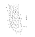
- FIG. 4 is an enlarged partial cross-sectional view of a static stator vane including leading edge erosion protection according to an embodiment of the present invention.
- FIG. 1 is a first stage fan section 11 of a typical gas turbofan engine, generally referenced 10.
- intake air represented by arrows 12 flows from into the engine 10, through a turbofan fan rotor 14, also referred to as an engine bypass fan, and toward a core engine, generally referenced 15.
- the intake air ultimately exits engine 10 through a turbine nozzle (not shown) located at the rear of the engine 10.
- a turbine nozzle Positioned behind the turbofan rotor 14 is a circumferential row of a plurality of composite stator vanes 16, of which only one is illustrated in FIG. 1.
- the plurality of composite stator vanes 16 are assembled into a stator hub 18 and a shroud ring 19 and supported with grommets, forming a stator vane assembly 20.
- the stator vane assembly 20 is installed in the engine 10 behind the turbofan rotor 14 and forward a front frame 21.
- the plurality of composite stator vanes 16 are formed from suitable vane material capable of withstanding the impact of incoming air and erosion. As shown, the composite stator vane 16 project radially outwardly from the stator hub 18 to the shroud ring 19. In this particular engine 10, multiple such composite stator vanes 16 are positioned in adjacent circumferential position along the stator hub 18 and the shroud ring 19.
- the composite stator vane 16 is typically a few inches in length and may have a different geometry and/or design than that illustrated, depending on the particular engine model in which it will be used and on its application. In general, the composite stator vane 16 is characterized by a complex geometry that changes in three dimensions. As illustrated, the composite stator vane 16 is an airfoil shaped structure that includes a concave face 20 and a convex face 22,which are preferably disposed on opposite sides of the composite stator vane 16.
- the composite stator vane 16 additionally includes a leading edge 24 and a trailing edge 26 which represent the edges of the composite stator vane 16 that firstly and lastly, respectively, encounter an air stream passing around it.
- high pressure intake air such as that generated by the turbofan rotor 14 (FIG. 1), impinges on the leading edge 24 of the composite stator vane 16 as indicated by directional arrows 28.
- the leading edge 24 is subject to wear, erosion, and degradation that partly arise from debris and contaminants, including operational fluids, dust, and sand that may be carried in the air stream 28, as well as an erosive operational environment. These debris and contaminants impact the leading edge 24 at high velocity thus leading to nicks, wear, and erosion, generally referenced as 30, all of which impair the performance of the turbofan engine 10 (FIG. 1).
- FIG. 3 illustrated in simplified cross-sectional view is a single composite stator vane 16 showing the leading edge 24 portion reinforced with a wire mesh 32 (described below). More specifically, illustrated is leading edge 24 having a portion indicated by dimension "x" that includes a corrosion resistant steel wire mesh screen 32 that is embedded in composite stator vane 16 during the molding process.
- dimension "x" is 0.3 inches, although this dimension could vary from about 0.1 to 0.5, inclusive.
- wire mesh screen 32 in this particular embodiment has a trailing edge 33 located approximately 0.3 inches from the leading edge 24 of composite stator vane 16.
- wire mesh screen in this particular embodiment has 120 wires per square inch, but wire mesh screens having fewer or greater wire per square inch, but typically between about 100 to 150 wires per square inch, inclusive, could also be used.
- FIG. 4 illustrated in further detail, is an enlarged partial cross-sectional view of leading edge 24 of the composite stator vane 16.
- the stainless steel mesh screen 32 allows a epoxy matrix resin 34 of a resin transfer molded (RTM) vane product to extrude to the external surface of the screen 32.
- Composite stator vane 16 is generally comprised of the epoxy matrix resin 34 or other polymer matrix, the wire mesh screen 32, and a graphite fiber 36 and an aramid fiber 38 wound and twisted preform that is embedded with the epoxy matrix resin 34 or other polymer matrix resin during the fabrication process, in combination referred to herein as a resin transfer molded composite.
- a thin tapering erosion protection layer 40 is deposited on the leading edge 24 of the composite stator vane 16 by careful masking of the plasma spray and thereby extends the life of the composite stator vane 16 and more particularly leading edge 24.
- Erosion protection layer 40 is preferably deposited by plasma spray coating, although alternate means of the application of erosion protection layer 40 to the composite stator vane 16 are anticipated by this disclosure.
- Erosion protection layer 40 is preferably applied by plasma spray on the leading edge 24 up to thickness of 0.010", but preferably having a thickness in a range of 0.003-0.005".
- Erosion protection layer 40 is tapered to a zero thickness from leading edge 24 to a trailing edge 33 of the wire mesh screen 32 by means of tools and spray masks.
- Layer 40 deposited on the wire mesh screen 32 of composite stator vane 16, is preferably comprised of at least one of the following materials: tungsten carbide, tungsten carbide-cobalt, cobalt, molybdenum, titanium carbide-nickel, chromium oxide, a high quality plasma sprayed erosion resistant bondcoat or top coat, and/or a nickel plasma sprayed coating.
- erosion protection layer 40 is comprised of a commercially available plasma sprayed Co (60) Mo 28 Cr 8.5 Si 2.5 Ni 1.5 alloy coating, such as Tribaloy® T400.
- This specific material provides many beneficial characteristics, including but not limited to: erosion and abrasion resistance, impact resistance, repair and rebuild operation, resistance to cavitation effects, resistance to chemical attack, galvanic corrosion control, sliding wear resistance, resistance to fretting, galling or adhesive wear, control of oxidation and sulfidation, atmospheric and heat corrosion control, thermal or electrical insulation, and clearance control.
- stator vane leading edge erosion can thus be solved by depositing on the leading edge 24 of the composite stator vane 16, preferably by plasma spray, an erosion protection layer 40 of material that is harder, tougher, and more resistant than the vane material.
- an erosion protection layer such as layer 40 described herein, is possible for a newly manufactured composite stator vane, as well as to repair existing composite stator vanes with a leading edge that includes a wire mesh screen.
- the addition of the erosion protection layer is cost effective in that several composite stator vanes may be coated at the same time reducing the cost of manufacture and repairs.
Landscapes
- Engineering & Computer Science (AREA)
- Chemical & Material Sciences (AREA)
- Materials Engineering (AREA)
- Mechanical Engineering (AREA)
- General Engineering & Computer Science (AREA)
- Composite Materials (AREA)
- Ceramic Engineering (AREA)
- Structures Of Non-Positive Displacement Pumps (AREA)
Applications Claiming Priority (2)
| Application Number | Priority Date | Filing Date | Title |
|---|---|---|---|
| US77732106P | 2006-02-28 | 2006-02-28 | |
| US11/413,755 US7435056B2 (en) | 2006-02-28 | 2006-04-28 | Leading edge erosion protection for composite stator vanes |
Publications (2)
| Publication Number | Publication Date |
|---|---|
| EP1826363A2 true EP1826363A2 (fr) | 2007-08-29 |
| EP1826363A3 EP1826363A3 (fr) | 2008-11-05 |
Family
ID=37888169
Family Applications (1)
| Application Number | Title | Priority Date | Filing Date |
|---|---|---|---|
| EP07103201A Withdrawn EP1826363A3 (fr) | 2006-02-28 | 2007-02-28 | Protection d'érosion du bord d'attaque d'une vanne en matériau composite |
Country Status (2)
| Country | Link |
|---|---|
| US (1) | US7435056B2 (fr) |
| EP (1) | EP1826363A3 (fr) |
Cited By (6)
| Publication number | Priority date | Publication date | Assignee | Title |
|---|---|---|---|---|
| WO2008116757A3 (fr) * | 2007-03-27 | 2009-01-15 | Alstom Technology Ltd | Pale de turbomachine avec revêtement de protection contre l'érosion et la corrosion, et procédé de fabrication de cette dernière |
| US8113787B2 (en) | 2007-06-20 | 2012-02-14 | Alstom Technology Ltd. | Turbomachine blade with erosion and corrosion protective coating and method of manufacturing |
| FR2975734A1 (fr) * | 2011-05-27 | 2012-11-30 | Snecma | Procede de renforcement d'une piece mecanique de turbomachine |
| CN103930750A (zh) * | 2011-11-15 | 2014-07-16 | 斯奈克玛 | 用于由3d机织复合材料制成的部件的设计 |
| DE102014226696A1 (de) * | 2014-12-19 | 2016-06-23 | Rolls-Royce Deutschland Ltd & Co Kg | Vorverdichtervorrichtung, Nachrüstsatz und Flugzeugtriebwerk |
| EP2336026A3 (fr) * | 2009-12-21 | 2017-05-24 | General Electric Company | Ensemble de nacelle intégré |
Families Citing this family (13)
| Publication number | Priority date | Publication date | Assignee | Title |
|---|---|---|---|---|
| GB0915087D0 (en) * | 2009-09-01 | 2009-09-30 | Rolls Royce Plc | Aerofoil with erosion resistant leading edge |
| GB201106276D0 (en) * | 2011-04-14 | 2011-05-25 | Rolls Royce Plc | Annulus filler system |
| US9404172B2 (en) | 2012-02-22 | 2016-08-02 | Sikorsky Aircraft Corporation | Erosion and fatigue resistant blade and blade coating |
| US9289826B2 (en) | 2012-09-17 | 2016-03-22 | Honeywell International Inc. | Turbine stator airfoil assemblies and methods for their manufacture |
| EP3090137B1 (fr) * | 2013-12-10 | 2020-04-22 | United Technologies Corporation | Liaison fusible pour système de revêtement de turbine à gaz |
| CN103692144B (zh) * | 2013-12-31 | 2016-08-17 | 湖南科技大学 | 一种碳化钨颗粒与树脂混合修复零部件的方法 |
| US9777593B2 (en) | 2015-02-23 | 2017-10-03 | General Electric Company | Hybrid metal and composite spool for rotating machinery |
| US10047763B2 (en) | 2015-12-14 | 2018-08-14 | General Electric Company | Rotor assembly for use in a turbofan engine and method of assembling |
| US10718350B2 (en) * | 2016-11-24 | 2020-07-21 | Pratt & Whitney Canada Corp. | Fan blade with galvanic separator |
| US11078588B2 (en) | 2017-01-09 | 2021-08-03 | Raytheon Technologies Corporation | Pulse plated abrasive grit |
| US20180319481A1 (en) * | 2017-05-05 | 2018-11-08 | Reed Chuda | Aircraft Spade Apparatus |
| US11441545B2 (en) | 2020-02-25 | 2022-09-13 | General Electric Company | Tungsten-based erosion-resistant leading edge protection cap for rotor blades |
| US12228037B1 (en) * | 2023-12-04 | 2025-02-18 | General Electric Company | Guide vane assembly with fixed and variable pitch inlet guide vanes |
Family Cites Families (19)
| Publication number | Priority date | Publication date | Assignee | Title |
|---|---|---|---|---|
| US3844728A (en) | 1968-03-20 | 1974-10-29 | United Aircraft Corp | Gas contacting element leading edge and trailing edge insert |
| US3892612A (en) | 1971-07-02 | 1975-07-01 | Gen Electric | Method for fabricating foreign object damage protection for rotar blades |
| US4006999A (en) | 1975-07-17 | 1977-02-08 | The United States Of America As Represented By The Administrator Of The National Aeronautics And Space Administration | Leading edge protection for composite blades |
| US4384452A (en) | 1978-10-26 | 1983-05-24 | Rice Ivan G | Steam-cooled blading with steam thermal barrier for reheat gas turbine combined with steam turbine |
| JP2566978B2 (ja) | 1987-08-28 | 1996-12-25 | 株式会社東芝 | 耐食合金鋼の製造方法 |
| US5702829A (en) | 1991-10-14 | 1997-12-30 | Commissariat A L'energie Atomique | Multilayer material, anti-erosion and anti-abrasion coating incorporating said multilayer material |
| DE4310896C1 (de) | 1993-04-02 | 1994-03-24 | Thyssen Industrie | Verfahren zum Herstellen von verschleißfesten Kanten an Turbinenschaufeln |
| US5603603A (en) | 1993-12-08 | 1997-02-18 | United Technologies Corporation | Abrasive blade tip |
| US5494404A (en) | 1993-12-22 | 1996-02-27 | Alliedsignal Inc. | Insertable stator vane assembly |
| US5449273A (en) | 1994-03-21 | 1995-09-12 | United Technologies Corporation | Composite airfoil leading edge protection |
| FR2745589B1 (fr) | 1996-02-29 | 1998-04-30 | Snecma | Piece hybride a haut rapport resistance-masse et procede de realisation |
| JPH1054204A (ja) * | 1996-05-20 | 1998-02-24 | General Electric Co <Ge> | ガスタービン用の多構成部翼 |
| DE19627860C1 (de) | 1996-07-11 | 1998-01-08 | Mtu Muenchen Gmbh | Schaufel für Strömungsmaschine mit metallischer Deckschicht |
| US6451454B1 (en) | 1999-06-29 | 2002-09-17 | General Electric Company | Turbine engine component having wear coating and method for coating a turbine engine component |
| US6485678B1 (en) * | 2000-06-20 | 2002-11-26 | Winsert Technologies, Inc. | Wear-resistant iron base alloys |
| US6575702B2 (en) | 2001-10-22 | 2003-06-10 | General Electric Company | Airfoils with improved strength and manufacture and repair thereof |
| US20040115470A1 (en) | 2002-12-12 | 2004-06-17 | Ackerman John Frederick | Thermal barrier coating protected by infiltrated alumina and method for preparing same |
| US7141110B2 (en) | 2003-11-21 | 2006-11-28 | General Electric Company | Erosion resistant coatings and methods thereof |
| US7300708B2 (en) | 2004-03-16 | 2007-11-27 | General Electric Company | Erosion and wear resistant protective structures for turbine engine components |
-
2006
- 2006-04-28 US US11/413,755 patent/US7435056B2/en not_active Expired - Fee Related
-
2007
- 2007-02-28 EP EP07103201A patent/EP1826363A3/fr not_active Withdrawn
Cited By (10)
| Publication number | Priority date | Publication date | Assignee | Title |
|---|---|---|---|---|
| WO2008116757A3 (fr) * | 2007-03-27 | 2009-01-15 | Alstom Technology Ltd | Pale de turbomachine avec revêtement de protection contre l'érosion et la corrosion, et procédé de fabrication de cette dernière |
| US8113787B2 (en) | 2007-06-20 | 2012-02-14 | Alstom Technology Ltd. | Turbomachine blade with erosion and corrosion protective coating and method of manufacturing |
| EP2336026A3 (fr) * | 2009-12-21 | 2017-05-24 | General Electric Company | Ensemble de nacelle intégré |
| FR2975734A1 (fr) * | 2011-05-27 | 2012-11-30 | Snecma | Procede de renforcement d'une piece mecanique de turbomachine |
| WO2012164205A1 (fr) * | 2011-05-27 | 2012-12-06 | Snecma | Procédé de renforcement d'une pièce mécanique |
| CN103562556A (zh) * | 2011-05-27 | 2014-02-05 | 斯奈克玛 | 加强机械零件的方法 |
| US9482102B2 (en) | 2011-05-27 | 2016-11-01 | Snecma | Method of reinforcing a mechanical part |
| CN103930750A (zh) * | 2011-11-15 | 2014-07-16 | 斯奈克玛 | 用于由3d机织复合材料制成的部件的设计 |
| CN103930750B (zh) * | 2011-11-15 | 2018-03-20 | 斯奈克玛 | 用于由3d机织复合材料制成的部件的设计 |
| DE102014226696A1 (de) * | 2014-12-19 | 2016-06-23 | Rolls-Royce Deutschland Ltd & Co Kg | Vorverdichtervorrichtung, Nachrüstsatz und Flugzeugtriebwerk |
Also Published As
| Publication number | Publication date |
|---|---|
| EP1826363A3 (fr) | 2008-11-05 |
| US7435056B2 (en) | 2008-10-14 |
| US20070201984A1 (en) | 2007-08-30 |
Similar Documents
| Publication | Publication Date | Title |
|---|---|---|
| EP1826363A2 (fr) | Protection d'érosion du bord d'attaque d'une vanne en matériau composite | |
| US10107302B2 (en) | Durable riblets for engine environment | |
| EP1672175A1 (fr) | Procédé d'application sur des éléments de turbines de revêtements du type MCrAlY résistant aux dommages de l'environment. | |
| EP3736414B1 (fr) | Pale à pointe abrasive et procédé de fabrication | |
| EP2753799B2 (fr) | Réparation de rainure de joint d'étanchéité de rotor | |
| EP3037570B1 (fr) | Procédé de formation d'un revêtement d'étanchéité | |
| EP3421732B1 (fr) | Joint d'étanchéité de moteur à turbine pour environnement d'érosion élevée | |
| EP4542003A1 (fr) | Moteur à turbine avec étage primaire de profils aérodynamiques et étage auxiliaire de profils aérodynamiques | |
| US20170211404A1 (en) | Blade outer air seal having surface layer with pockets | |
| EP3839096A1 (fr) | Barrière de diffusion pour empêcher la déplétion du super alliage dans le revêtement des pointes de lame en nickel-cbn | |
| US12385405B2 (en) | Wear resistant article and method of making | |
| US12480417B2 (en) | Cold spray duct for a gas turbine engine | |
| US12129769B2 (en) | Erosion-shielded turbine blades and methods of manufacturing the same | |
| EP4397788A1 (fr) | Article résistant à l'usure et procédé de fabrication | |
| US12297746B2 (en) | Erosion compensated vane geometry | |
| US20240191358A1 (en) | Electroless deposited coating with stiffeners | |
| US20240286960A1 (en) | Coating system and method for maintenance thereof | |
| US11773732B2 (en) | Rotor blade with protective layer | |
| EP4636224A1 (fr) | Revêtement segmenté géométriquement pour isolation thermique et protection contre l'abradabilité | |
| CN118291974A (zh) | 耐磨制品及制造方法 | |
| CN118273976A (zh) | 复合翼型件组件及其制造方法 |
Legal Events
| Date | Code | Title | Description |
|---|---|---|---|
| PUAI | Public reference made under article 153(3) epc to a published international application that has entered the european phase |
Free format text: ORIGINAL CODE: 0009012 |
|
| AK | Designated contracting states |
Kind code of ref document: A2 Designated state(s): AT BE BG CH CY CZ DE DK EE ES FI FR GB GR HU IE IS IT LI LT LU LV MC NL PL PT RO SE SI SK TR |
|
| AX | Request for extension of the european patent |
Extension state: AL BA HR MK YU |
|
| PUAL | Search report despatched |
Free format text: ORIGINAL CODE: 0009013 |
|
| AK | Designated contracting states |
Kind code of ref document: A3 Designated state(s): AT BE BG CH CY CZ DE DK EE ES FI FR GB GR HU IE IS IT LI LT LU LV MC NL PL PT RO SE SI SK TR |
|
| AX | Request for extension of the european patent |
Extension state: AL BA HR MK RS |
|
| 17P | Request for examination filed |
Effective date: 20090423 |
|
| AKX | Designation fees paid |
Designated state(s): DE FR GB |
|
| 17Q | First examination report despatched |
Effective date: 20090701 |
|
| STAA | Information on the status of an ep patent application or granted ep patent |
Free format text: STATUS: THE APPLICATION IS DEEMED TO BE WITHDRAWN |
|
| 18D | Application deemed to be withdrawn |
Effective date: 20110901 |