EP1826408A2 - Pompe de dosage avec auto-étalonnage et prédiction de l'état de santé - Google Patents
Pompe de dosage avec auto-étalonnage et prédiction de l'état de santé Download PDFInfo
- Publication number
- EP1826408A2 EP1826408A2 EP07250722A EP07250722A EP1826408A2 EP 1826408 A2 EP1826408 A2 EP 1826408A2 EP 07250722 A EP07250722 A EP 07250722A EP 07250722 A EP07250722 A EP 07250722A EP 1826408 A2 EP1826408 A2 EP 1826408A2
- Authority
- EP
- European Patent Office
- Prior art keywords
- system operating
- pump
- current
- function level
- measured
- Prior art date
- Legal status (The legal status is an assumption and is not a legal conclusion. Google has not performed a legal analysis and makes no representation as to the accuracy of the status listed.)
- Granted
Links
- 238000000034 method Methods 0.000 claims abstract description 23
- 230000007423 decrease Effects 0.000 claims description 5
- 230000003247 decreasing effect Effects 0.000 claims description 5
- 238000005259 measurement Methods 0.000 claims description 4
- 238000005086 pumping Methods 0.000 claims 2
- 238000012544 monitoring process Methods 0.000 abstract description 15
- 238000012360 testing method Methods 0.000 abstract description 4
- 239000012530 fluid Substances 0.000 description 6
- 238000013461 design Methods 0.000 description 4
- 239000000446 fuel Substances 0.000 description 3
- 238000004519 manufacturing process Methods 0.000 description 2
- 230000033228 biological regulation Effects 0.000 description 1
- 230000001419 dependent effect Effects 0.000 description 1
- 230000007613 environmental effect Effects 0.000 description 1
- 238000012986 modification Methods 0.000 description 1
- 230000004048 modification Effects 0.000 description 1
- 230000001105 regulatory effect Effects 0.000 description 1
Images
Classifications
-
- F—MECHANICAL ENGINEERING; LIGHTING; HEATING; WEAPONS; BLASTING
- F04—POSITIVE - DISPLACEMENT MACHINES FOR LIQUIDS; PUMPS FOR LIQUIDS OR ELASTIC FLUIDS
- F04B—POSITIVE-DISPLACEMENT MACHINES FOR LIQUIDS; PUMPS
- F04B51/00—Testing machines, pumps, or pumping installations
-
- F—MECHANICAL ENGINEERING; LIGHTING; HEATING; WEAPONS; BLASTING
- F04—POSITIVE - DISPLACEMENT MACHINES FOR LIQUIDS; PUMPS FOR LIQUIDS OR ELASTIC FLUIDS
- F04B—POSITIVE-DISPLACEMENT MACHINES FOR LIQUIDS; PUMPS
- F04B49/00—Control, e.g. of pump delivery, or pump pressure of, or safety measures for, machines, pumps, or pumping installations, not otherwise provided for, or of interest apart from, groups F04B1/00 - F04B47/00
- F04B49/06—Control using electricity
- F04B49/065—Control using electricity and making use of computers
-
- F—MECHANICAL ENGINEERING; LIGHTING; HEATING; WEAPONS; BLASTING
- F04—POSITIVE - DISPLACEMENT MACHINES FOR LIQUIDS; PUMPS FOR LIQUIDS OR ELASTIC FLUIDS
- F04C—ROTARY-PISTON, OR OSCILLATING-PISTON, POSITIVE-DISPLACEMENT MACHINES FOR LIQUIDS; ROTARY-PISTON, OR OSCILLATING-PISTON, POSITIVE-DISPLACEMENT PUMPS
- F04C14/00—Control of, monitoring of, or safety arrangements for, machines, pumps or pumping installations
- F04C14/08—Control of, monitoring of, or safety arrangements for, machines, pumps or pumping installations characterised by varying the rotational speed
-
- F—MECHANICAL ENGINEERING; LIGHTING; HEATING; WEAPONS; BLASTING
- F04—POSITIVE - DISPLACEMENT MACHINES FOR LIQUIDS; PUMPS FOR LIQUIDS OR ELASTIC FLUIDS
- F04B—POSITIVE-DISPLACEMENT MACHINES FOR LIQUIDS; PUMPS
- F04B2201/00—Pump parameters
- F04B2201/08—Cylinder or housing parameters
- F04B2201/0803—Leakage
-
- F—MECHANICAL ENGINEERING; LIGHTING; HEATING; WEAPONS; BLASTING
- F04—POSITIVE - DISPLACEMENT MACHINES FOR LIQUIDS; PUMPS FOR LIQUIDS OR ELASTIC FLUIDS
- F04B—POSITIVE-DISPLACEMENT MACHINES FOR LIQUIDS; PUMPS
- F04B2203/00—Motor parameters
- F04B2203/02—Motor parameters of rotating electric motors
- F04B2203/0201—Current
-
- F—MECHANICAL ENGINEERING; LIGHTING; HEATING; WEAPONS; BLASTING
- F04—POSITIVE - DISPLACEMENT MACHINES FOR LIQUIDS; PUMPS FOR LIQUIDS OR ELASTIC FLUIDS
- F04B—POSITIVE-DISPLACEMENT MACHINES FOR LIQUIDS; PUMPS
- F04B2203/00—Motor parameters
- F04B2203/02—Motor parameters of rotating electric motors
- F04B2203/0209—Rotational speed
-
- F—MECHANICAL ENGINEERING; LIGHTING; HEATING; WEAPONS; BLASTING
- F04—POSITIVE - DISPLACEMENT MACHINES FOR LIQUIDS; PUMPS FOR LIQUIDS OR ELASTIC FLUIDS
- F04C—ROTARY-PISTON, OR OSCILLATING-PISTON, POSITIVE-DISPLACEMENT MACHINES FOR LIQUIDS; ROTARY-PISTON, OR OSCILLATING-PISTON, POSITIVE-DISPLACEMENT PUMPS
- F04C2220/00—Application
- F04C2220/24—Application for metering throughflow
-
- F—MECHANICAL ENGINEERING; LIGHTING; HEATING; WEAPONS; BLASTING
- F04—POSITIVE - DISPLACEMENT MACHINES FOR LIQUIDS; PUMPS FOR LIQUIDS OR ELASTIC FLUIDS
- F04C—ROTARY-PISTON, OR OSCILLATING-PISTON, POSITIVE-DISPLACEMENT MACHINES FOR LIQUIDS; ROTARY-PISTON, OR OSCILLATING-PISTON, POSITIVE-DISPLACEMENT PUMPS
- F04C2240/00—Components
- F04C2240/80—Other components
- F04C2240/81—Sensor, e.g. electronic sensor for control or monitoring
-
- F—MECHANICAL ENGINEERING; LIGHTING; HEATING; WEAPONS; BLASTING
- F04—POSITIVE - DISPLACEMENT MACHINES FOR LIQUIDS; PUMPS FOR LIQUIDS OR ELASTIC FLUIDS
- F04C—ROTARY-PISTON, OR OSCILLATING-PISTON, POSITIVE-DISPLACEMENT MACHINES FOR LIQUIDS; ROTARY-PISTON, OR OSCILLATING-PISTON, POSITIVE-DISPLACEMENT PUMPS
- F04C2270/00—Control; Monitoring or safety arrangements
- F04C2270/80—Diagnostics
-
- F—MECHANICAL ENGINEERING; LIGHTING; HEATING; WEAPONS; BLASTING
- F04—POSITIVE - DISPLACEMENT MACHINES FOR LIQUIDS; PUMPS FOR LIQUIDS OR ELASTIC FLUIDS
- F04C—ROTARY-PISTON, OR OSCILLATING-PISTON, POSITIVE-DISPLACEMENT MACHINES FOR LIQUIDS; ROTARY-PISTON, OR OSCILLATING-PISTON, POSITIVE-DISPLACEMENT PUMPS
- F04C2270/00—Control; Monitoring or safety arrangements
- F04C2270/86—Detection
Definitions
- This application relates generally to a metering pump for gas turbine engine that includes a method of self-calibration and health-monitoring.
- a demand flow system traditionally includes a controller, a motor and a pump.
- the demand flow system functions as a metering system to regulate fuel delivery to, for example, a gas turbine engine. Fuel regulation is traditionally accomplished by direct control of the pump, also known as a metering pump.
- the metering pump includes a motor, where speed is varied to provide a desired flow. The effectiveness of the demand flow system is dependent on the accuracy of the control of the motor and the tolerances of the pump.
- Known demand flow systems are typically calibrated only upon initial manufacture.
- system accuracy includes both determining system accuracy at an initial system start-up and monitoring system accuracy or "health" throughout the life of the system. Because the systems are calibrated at initial manufacture, and due to system variations based on allowable system tolerances and changes in the system operating environment, the demand flow system may not meet desired operational requirements throughout the life of the product.
- a metering pump that is operable to self-calibrate at initial start-up and which includes a health-monitoring system that allows the system to monitor performance and re-calibrate to compensate for performance losses.
- a metering pump of an embodiment of the present invention disclosed herein incorporates a method of relating inner loop current to pump output pressure for a demand flow system. It has been determined that a system current is proportional to a pump delivered pressure. Because each pump by design has pre-defined characteristics of backpressure and flow at a given speed, a relationship can be developed that can determine the operating condition or the "health" of the system by utilizing information such as the pump/motor speed, an operating temperature, and the system current, for example.
- the pump/motor speed is measured and controlled by a system controller.
- a system temperature is also measured by the system controller.
- the controller monitors the measured system temperature and provides for compensation for system losses, including inductive-resistive (IR) losses, and for density and viscosity shifts, within a pre-determined allowable system temperature operating range.
- IR inductive-resistive
- the system controller uses a root mean square (RMS) method of current measurement to measure the current through an inner loop of the system. This is accomplished through either direct measurement or indirect measurement of the current by the system controller.
- RMS root mean square
- the health-monitoring feature continues to monitor the current as an indicator of pump performance and continuously adjusts motor speed to maintain a desired level of pump performance. This provides the system with the ability to compensate for performance losses, including performance losses due to variations in operating conditions, and to compensate for pump wear.
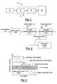
- FIG. 1 schematically illustrates an example demand flow system 10 including a metering pump 14 of the present invention.
- a system controller 12 controls a current transmitted to a motor 16.
- the motor 16 controls a pump 18, which provides a desired flow of fluid, e.g. fuel, to a device 20.
- the device 20 is a gas turbine engine, however, the device 20 may be any device that requires regulated delivery of a fluid.
- An amount of current transmitted to the motor 16 is directly related to a speed of the motor 16.
- the speed of the motor 16 is proportional to a pressure of a fluid delivered by the pump 18 to the gas turbine engine 20.
- the pressure of the fluid delivered by the pump 18 correlates to a flow of fluid from the pump 18 to the gas turbine engine 20. As such, a relationship exists between the amount of current transmitted to the motor 16 and the flow of fluid from the pump 18.
- BFM Base Flow Map
- the health-monitoring feature continues to monitor the current as an indicator of pump performance and continuously adjusts motor speed to maintain a desired level of pump performance.
- This allows the system the ability to compensate for performance losses, including performance losses due to variations in operating conditions, and to compensate for pump wear. For example, when an actual measured pump leakage is greater than an expected pump leakage, the controller 12 will increase the current delivered to the motor 16, which in turn increases an actual flow delivered from the pump 18 to the gas turbine engine 20, to accommodate for the additional pump leakage. Conversely, when the actual measured pump leakage is less than the expected leakage, the controller 12 will decrease the current delivered to the motor 16, which in turn decreases the actual flow delivered from the pump 18 to the gas turbine engine 20. This adjustment is reflected in an adjusted BFM. The health-monitoring process is repeated continuously throughout the daily operation of the system 10 and throughout the life of the system 10.
- FIG. 2 schematically illustrates a method of self-calibration and dynamic system adjustment for a metering pump 14 according to one embodiment of the present invention.
- a Flow Reference FR
- the FR is generated by the controller 12 based upon known system characteristics, for example, backpressure and/or flow, which are indicative of pump leakage.
- the BFM illustrates how the FR varies as a function of motor speed. As such, the BFM is used as a baseline for initial system performance.
- SDC1 First System Dynamic Compensation
- the SDC1 is an initial calibration stage conducted using the "shut-off" test as described above. Under these conditions, the pump 18 is “dead-headed” and the only “flow” is pump leakage.
- the controller 12 adjusts the FR based upon a Dynamic Constant (DC1) to accommodate for a variation in system operating conditions. This allows the system 10 to conduct an initial self-calibration that includes adjusting the BFM based upon the actual system operating conditions by compensating for actual component tolerances, i.e. compensation for a tight pump or a loose pump.
- DC1 Dynamic Constant
- the DC1 is initial pump leakage and the controller 12 adjusts the FR to account for deviation of an actual measured leakage measured from the initial pump leakage expected based upon the original FR.
- the original FR which was generated based upon known system characteristics, is used to generate the BFM.
- the known system characteristics can vary within an allowable tolerance range based upon actual dimensions of the pump 18.
- the SDC1 calibration stage accommodates for this variation by determining the initial pump leakage, which is indicative of the tightness or looseness of the pump 18 as discussed above, and adjusting the BFM respectively by increasing or decreasing the pump speed associated with a desired flow request to account for the initial pump leakage and provide the desired flow regardless of the initial pump leakage.
- the system includes a Second System Dynamic Adjustment (SDC2) that operates continuously throughout system operation and functions as a health-monitoring system feature throughout the life of the system to accommodate for changes in the system operating conditions including component wear and environmental factors, e.g. temperature variation.
- SDC2 Second System Dynamic Adjustment
- the SDC2 incorporates a health-monitoring relationship into the system.
- the health-monitoring relationship monitors an operating characteristic associated with the system and adjusts the operating characteristic to achieve and maintain a desired system operating function level.
- the monitored operating characteristic is RMS current and the desired system operating function level is Normal System Function.
- FIG. 3 graphically illustrates an example of a health-monitoring relationship between system operating characteristics and system operating function levels according to one embodiment of the present invention.
- the system operating characteristic is RMS Current, which is directly related to motor speed
- the System Health Factor is pump leakage, which is a function of system pressure.
- a relationship is defined between the RMS Current and the pump leakage.
- a Nominal Characteristic line (NCL) is determined based upon the relationship and a Nominal Characteristic Range (NCR) is defined based as a function of system temperature variation.
- System Operating Function Levels (SOFL) are defined along the NCL. In this example system, the SOFL's include: Strong System, Normal System Function, Weak Pump, and System Ready to be Removed.
- An initial SOFL is determined during initial calibration of the system.
- the initial SOFL is based upon the RMS current required to produce a desired flow at a nominal temperature and is adjusted during initial calibration to account for pump leakage associated with initial pump tolerances.
- the RMS current is directly related to motor speed. As such, if the initial SOFL is Strong System, then the controller will reduce the motor speed to produce the desired flow and reduce the SOFL to Normal System Function. Conversely, if the initial SOFL is below Normal System Function, then the controller will attempt to increase the motor speed to produce the desired flow and bring the SOFL up to Normal System Function.
- the controller 12 will increase the motor speed to accommodate for pump wear to ensure the desired flow and the SOFL of Normal System Function are achieved.
- the increase in motor speed generates an increase in the current provided to the motor 16, and the increase in current is proportional to the pressure produced by the pump 18.
- the SOFL will reach the last level - System Ready to be Removed, which indicates that the pump 18 has reached a critical wear level and the system is unable to accommodate for the losses at this level. That is, pump leakage within the system has reached a critical level and the pump should be replaced.
- the method of the present invention is not limited to metering pumps, it may also be applied to pumps including other types of motors, for example, a switch-reluctance (SR) motor or "stepper" motor.
- SR switch-reluctance
- phase current would be measured instead of RMS current.
Landscapes
- Engineering & Computer Science (AREA)
- Mechanical Engineering (AREA)
- General Engineering & Computer Science (AREA)
- Computer Hardware Design (AREA)
- Control Of Positive-Displacement Pumps (AREA)
- Control Of Non-Positive-Displacement Pumps (AREA)
Applications Claiming Priority (1)
| Application Number | Priority Date | Filing Date | Title |
|---|---|---|---|
| US11/359,191 US7798781B2 (en) | 2006-02-22 | 2006-02-22 | Metering pump with self-calibration and health prediction |
Publications (3)
| Publication Number | Publication Date |
|---|---|
| EP1826408A2 true EP1826408A2 (fr) | 2007-08-29 |
| EP1826408A3 EP1826408A3 (fr) | 2010-12-22 |
| EP1826408B1 EP1826408B1 (fr) | 2018-08-22 |
Family
ID=38051862
Family Applications (1)
| Application Number | Title | Priority Date | Filing Date |
|---|---|---|---|
| EP07250722.1A Ceased EP1826408B1 (fr) | 2006-02-22 | 2007-02-21 | Pompe de dosage avec auto-étalonnage et prédiction de l'état de santé |
Country Status (3)
| Country | Link |
|---|---|
| US (1) | US7798781B2 (fr) |
| EP (1) | EP1826408B1 (fr) |
| JP (1) | JP4606425B2 (fr) |
Cited By (8)
| Publication number | Priority date | Publication date | Assignee | Title |
|---|---|---|---|---|
| WO2011008874A1 (fr) * | 2009-07-15 | 2011-01-20 | Integrated Designs, L.P. | Système et procédé pour déterminer la pression d'une pompe sur la base du courant moteur |
| CN104343671A (zh) * | 2013-07-31 | 2015-02-11 | 上海理工大学 | 气泵性能测试系统 |
| EP3135911A1 (fr) * | 2015-08-25 | 2017-03-01 | Airbus Operations Limited | Surveillance de pompe médicale |
| CN108194343A (zh) * | 2017-12-23 | 2018-06-22 | 东北大学 | 一种真空泵测试系统及测试方法 |
| EP3378827B1 (fr) | 2017-03-24 | 2019-12-25 | STILL GmbH | Procédé de fonctionnement d'une installation hydraulique d'un chariot de manutention |
| US10711788B2 (en) | 2015-12-17 | 2020-07-14 | Wayne/Scott Fetzer Company | Integrated sump pump controller with status notifications |
| USD890211S1 (en) | 2018-01-11 | 2020-07-14 | Wayne/Scott Fetzer Company | Pump components |
| USD893552S1 (en) | 2017-06-21 | 2020-08-18 | Wayne/Scott Fetzer Company | Pump components |
Families Citing this family (13)
| Publication number | Priority date | Publication date | Assignee | Title |
|---|---|---|---|---|
| US8196464B2 (en) | 2010-01-05 | 2012-06-12 | The Raymond Corporation | Apparatus and method for monitoring a hydraulic pump on a material handling vehicle |
| US9057372B2 (en) | 2010-12-06 | 2015-06-16 | Hamilton Sundstrand Corporation | Gear root geometry for increased carryover volume |
| JP5859279B2 (ja) * | 2011-11-07 | 2016-02-10 | 住友重機械工業株式会社 | 油圧閉回路システム |
| CN103827509B (zh) * | 2011-11-07 | 2016-04-20 | 住友重机械工业株式会社 | 液压闭环系统 |
| JP2015536233A (ja) * | 2012-10-25 | 2015-12-21 | グラコ ミネソタ インコーポレーテッド | ホットメルト供給システムのための電力制御 |
| CN105518305B (zh) | 2013-07-25 | 2018-09-14 | 流体处理有限责任公司 | 用于液体循环泵送系统的具有自校准装置的无传感器自适应泵控制 |
| AT514517B1 (de) * | 2014-11-05 | 2016-06-15 | Avl List Gmbh | Verfahren und Vorrichtung zum Betreiben einer Pumpe |
| DE102015015153B4 (de) * | 2015-11-25 | 2019-10-17 | Dräger Safety AG & Co. KGaA | Verfahren zur Überprüfung einer Pumpeneinrichtung in einem Gasmessystem |
| EP3715632B9 (fr) * | 2019-03-26 | 2023-07-12 | Grifols, S.A. | Procédé d'étalonnage d'une pompe péristaltique, procédé de distribution d'une quantité de liquide au moyen d'une pompe péristaltique et dispositif de production de préparations stériles pouvant exécuter lesdits procédés |
| US20220154714A1 (en) * | 2020-11-19 | 2022-05-19 | Haier Us Appliance Solutions, Inc. | Linear compressor and internal collision mitigation |
| CN113107832B (zh) * | 2021-04-25 | 2022-08-26 | 西安热工研究院有限公司 | 一种测试带勺管调节的电动给水泵特性的方法 |
| US20240329619A1 (en) * | 2022-03-31 | 2024-10-03 | J. Michael Shifflette | Frequency Domain Work Analysis of Machinery including Turbomachinery |
| CN116292242B (zh) * | 2023-01-13 | 2024-03-12 | 合肥新沪屏蔽泵有限公司 | 一种水泵加速寿命测试系统 |
Citations (1)
| Publication number | Priority date | Publication date | Assignee | Title |
|---|---|---|---|---|
| US20030194326A1 (en) | 2002-04-12 | 2003-10-16 | Bettenhausen Craig A. | Electronic trim for a variable delivery pump in a hydraulic system for an engine |
Family Cites Families (12)
| Publication number | Priority date | Publication date | Assignee | Title |
|---|---|---|---|---|
| US5112196A (en) * | 1990-12-21 | 1992-05-12 | Beta Machinery Analysis Ltd. | Method and apparatus for analyzing the operating condition of a machine |
| GB9310786D0 (en) * | 1993-05-25 | 1993-07-14 | Walker Ian R | Circulation pump for high purity gases at high pressures |
| US5941305A (en) * | 1998-01-29 | 1999-08-24 | Patton Enterprises, Inc. | Real-time pump optimization system |
| DE19810764B4 (de) * | 1998-03-12 | 2005-05-25 | Continental Aktiengesellschaft | Bedarfsabhängig ein- und ausschaltbarer Kompressor und Verfahren zur Steuerung bzw Regelung eines solchen Kompressors |
| KR100438957B1 (ko) * | 2001-12-22 | 2004-07-03 | 주식회사 엘지이아이 | 스크롤 압축기의 과부하 방지장치 |
| JP4197101B2 (ja) * | 2002-03-05 | 2008-12-17 | パナソニックエコシステムズ株式会社 | ファンモータおよびそれを搭載した換気装置 |
| US20030223877A1 (en) * | 2002-06-04 | 2003-12-04 | Ametek, Inc. | Blower assembly with closed-loop feedback |
| DE10244203A1 (de) * | 2002-09-23 | 2004-04-01 | Robert Bosch Gmbh | Verfahren und Vorrichtung zur Erfassung der Drehzahl einer Pumpe |
| US6941785B2 (en) * | 2003-05-13 | 2005-09-13 | Ut-Battelle, Llc | Electric fuel pump condition monitor system using electrical signature analysis |
| GB0323887D0 (en) * | 2003-10-11 | 2003-11-12 | Goodrich Control Sys Ltd | Pump health monitoring |
| US8540493B2 (en) * | 2003-12-08 | 2013-09-24 | Sta-Rite Industries, Llc | Pump control system and method |
| US7140240B2 (en) * | 2004-06-21 | 2006-11-28 | Hamilton Sundstrand | Electric engine start system with inspection mode |
-
2006
- 2006-02-22 US US11/359,191 patent/US7798781B2/en not_active Expired - Fee Related
-
2007
- 2007-02-14 JP JP2007032812A patent/JP4606425B2/ja not_active Expired - Fee Related
- 2007-02-21 EP EP07250722.1A patent/EP1826408B1/fr not_active Ceased
Patent Citations (1)
| Publication number | Priority date | Publication date | Assignee | Title |
|---|---|---|---|---|
| US20030194326A1 (en) | 2002-04-12 | 2003-10-16 | Bettenhausen Craig A. | Electronic trim for a variable delivery pump in a hydraulic system for an engine |
Cited By (16)
| Publication number | Priority date | Publication date | Assignee | Title |
|---|---|---|---|---|
| WO2011008874A1 (fr) * | 2009-07-15 | 2011-01-20 | Integrated Designs, L.P. | Système et procédé pour déterminer la pression d'une pompe sur la base du courant moteur |
| US20110030484A1 (en) * | 2009-07-15 | 2011-02-10 | Integrated Designs, L.P. | System and method for determining pump pressure based on motor current |
| JP2012533975A (ja) * | 2009-07-15 | 2012-12-27 | インテグレイテッド・デザインズ・リミテッド・パートナーシップ | モーター電流に基づいてポンプ圧を決定するシステムおよび方法 |
| US8441222B2 (en) | 2009-07-15 | 2013-05-14 | Integrated Designs, L.P. | System and method for determining pump pressure based on motor current |
| TWI495889B (zh) * | 2009-07-15 | 2015-08-11 | Integrated Designs L P | 用以基於馬達電流判定泵壓力的系統及方法 |
| CN104343671A (zh) * | 2013-07-31 | 2015-02-11 | 上海理工大学 | 气泵性能测试系统 |
| US10160553B2 (en) | 2015-08-25 | 2018-12-25 | Airbus Operations Limited | Pump health monitoring |
| EP3135911A1 (fr) * | 2015-08-25 | 2017-03-01 | Airbus Operations Limited | Surveillance de pompe médicale |
| US10711788B2 (en) | 2015-12-17 | 2020-07-14 | Wayne/Scott Fetzer Company | Integrated sump pump controller with status notifications |
| US11486401B2 (en) | 2015-12-17 | 2022-11-01 | Wayne/Scott Fetzer Company | Integrated sump pump controller with status notifications |
| EP3378827B1 (fr) | 2017-03-24 | 2019-12-25 | STILL GmbH | Procédé de fonctionnement d'une installation hydraulique d'un chariot de manutention |
| USD893552S1 (en) | 2017-06-21 | 2020-08-18 | Wayne/Scott Fetzer Company | Pump components |
| USD1015378S1 (en) | 2017-06-21 | 2024-02-20 | Wayne/Scott Fetzer Company | Pump components |
| CN108194343A (zh) * | 2017-12-23 | 2018-06-22 | 东北大学 | 一种真空泵测试系统及测试方法 |
| USD890211S1 (en) | 2018-01-11 | 2020-07-14 | Wayne/Scott Fetzer Company | Pump components |
| USD1014560S1 (en) | 2018-01-11 | 2024-02-13 | Wayne/Scott Fetzer Company | Pump components |
Also Published As
| Publication number | Publication date |
|---|---|
| JP2007224904A (ja) | 2007-09-06 |
| US20070196213A1 (en) | 2007-08-23 |
| JP4606425B2 (ja) | 2011-01-05 |
| US7798781B2 (en) | 2010-09-21 |
| EP1826408A3 (fr) | 2010-12-22 |
| EP1826408B1 (fr) | 2018-08-22 |
Similar Documents
| Publication | Publication Date | Title |
|---|---|---|
| EP1826408A2 (fr) | Pompe de dosage avec auto-étalonnage et prédiction de l'état de santé | |
| US10221801B2 (en) | Pressure control by phase current and initial adjustment at car line | |
| US6234759B1 (en) | Method for regulating a fluid pressure | |
| KR101637571B1 (ko) | 건설기계의 유압펌프 제어장치 및 제어방법 | |
| CN101498249B (zh) | 用于调节固定式燃气发动机的方法 | |
| US7762080B2 (en) | Fuel metering pump calibration method | |
| CN109458355B (zh) | 压缩机的喘振控制方法及压缩机的喘振控制系统 | |
| US8384332B2 (en) | Integrated gearbox/encoder and control system | |
| EP0570114A1 (fr) | Système et procédé de commande pour un moteur propulsant un compressor | |
| HK1044131B (zh) | 從壓力容器中提供流體的方法和裝置 | |
| EP1344917B1 (fr) | Système de régulation d'alimentation en carburant | |
| US7530216B2 (en) | Control system for a gas turbine engine | |
| CN107002662A (zh) | 用于运行泵的方法和装置 | |
| CN107002574B (zh) | 用于运行柴油发动机的方法 | |
| CN110873041B (zh) | 具有调节工作范围的控制功能部的压缩机或泵和工作方法 | |
| US7684947B2 (en) | Method for matching the actual characteristic curve of a hydrodynamic component to a predefined set characteristics curve during the final test of the hydrodynamic component | |
| EP1752638B1 (fr) | Agencement et méthode de régulation d'une turbine à gaz | |
| US20160377000A1 (en) | Method for operating a gas turbine installation and the same | |
| EP2192292A1 (fr) | Régulateur de vitesse de rotation | |
| US20120174592A1 (en) | Method for operating a gas turbine | |
| RU2504678C1 (ru) | Автоматическая самонастраивающаяся микропроцессорная система регулирования частоты вращения вала тепловой машины | |
| KR20040031095A (ko) | 엔진 제어 방법 및 장치 |
Legal Events
| Date | Code | Title | Description |
|---|---|---|---|
| PUAI | Public reference made under article 153(3) epc to a published international application that has entered the european phase |
Free format text: ORIGINAL CODE: 0009012 |
|
| AK | Designated contracting states |
Kind code of ref document: A2 Designated state(s): AT BE BG CH CY CZ DE DK EE ES FI FR GB GR HU IE IS IT LI LT LU LV MC NL PL PT RO SE SI SK TR |
|
| AX | Request for extension of the european patent |
Extension state: AL BA HR MK YU |
|
| PUAL | Search report despatched |
Free format text: ORIGINAL CODE: 0009013 |
|
| AK | Designated contracting states |
Kind code of ref document: A3 Designated state(s): AT BE BG CH CY CZ DE DK EE ES FI FR GB GR HU IE IS IT LI LT LU LV MC NL PL PT RO SE SI SK TR |
|
| AX | Request for extension of the european patent |
Extension state: AL BA HR MK RS |
|
| RIC1 | Information provided on ipc code assigned before grant |
Ipc: F04B 51/00 20060101AFI20070531BHEP Ipc: F04B 49/06 20060101ALI20101115BHEP Ipc: F04C 14/08 20060101ALI20101115BHEP Ipc: F04D 15/00 20060101ALI20101115BHEP |
|
| 17P | Request for examination filed |
Effective date: 20110622 |
|
| AKX | Designation fees paid |
Designated state(s): DE FR GB IT |
|
| 17Q | First examination report despatched |
Effective date: 20150608 |
|
| GRAP | Despatch of communication of intention to grant a patent |
Free format text: ORIGINAL CODE: EPIDOSNIGR1 |
|
| STAA | Information on the status of an ep patent application or granted ep patent |
Free format text: STATUS: GRANT OF PATENT IS INTENDED |
|
| INTG | Intention to grant announced |
Effective date: 20180307 |
|
| GRAS | Grant fee paid |
Free format text: ORIGINAL CODE: EPIDOSNIGR3 |
|
| GRAA | (expected) grant |
Free format text: ORIGINAL CODE: 0009210 |
|
| STAA | Information on the status of an ep patent application or granted ep patent |
Free format text: STATUS: THE PATENT HAS BEEN GRANTED |
|
| AK | Designated contracting states |
Kind code of ref document: B1 Designated state(s): DE FR GB IT |
|
| REG | Reference to a national code |
Ref country code: GB Ref legal event code: FG4D |
|
| REG | Reference to a national code |
Ref country code: DE Ref legal event code: R096 Ref document number: 602007055824 Country of ref document: DE |
|
| REG | Reference to a national code |
Ref country code: DE Ref legal event code: R097 Ref document number: 602007055824 Country of ref document: DE |
|
| PLBE | No opposition filed within time limit |
Free format text: ORIGINAL CODE: 0009261 |
|
| STAA | Information on the status of an ep patent application or granted ep patent |
Free format text: STATUS: NO OPPOSITION FILED WITHIN TIME LIMIT |
|
| 26N | No opposition filed |
Effective date: 20190523 |
|
| PGFP | Annual fee paid to national office [announced via postgrant information from national office to epo] |
Ref country code: DE Payment date: 20200121 Year of fee payment: 14 Ref country code: IT Payment date: 20200121 Year of fee payment: 14 Ref country code: GB Payment date: 20200123 Year of fee payment: 14 |
|
| PGFP | Annual fee paid to national office [announced via postgrant information from national office to epo] |
Ref country code: FR Payment date: 20200122 Year of fee payment: 14 |
|
| REG | Reference to a national code |
Ref country code: DE Ref legal event code: R119 Ref document number: 602007055824 Country of ref document: DE |
|
| GBPC | Gb: european patent ceased through non-payment of renewal fee |
Effective date: 20210221 |
|
| PG25 | Lapsed in a contracting state [announced via postgrant information from national office to epo] |
Ref country code: DE Free format text: LAPSE BECAUSE OF NON-PAYMENT OF DUE FEES Effective date: 20210901 Ref country code: GB Free format text: LAPSE BECAUSE OF NON-PAYMENT OF DUE FEES Effective date: 20210221 Ref country code: FR Free format text: LAPSE BECAUSE OF NON-PAYMENT OF DUE FEES Effective date: 20210228 |
|
| PG25 | Lapsed in a contracting state [announced via postgrant information from national office to epo] |
Ref country code: IT Free format text: LAPSE BECAUSE OF NON-PAYMENT OF DUE FEES Effective date: 20210221 |