EP3135911A1 - Surveillance de pompe médicale - Google Patents
Surveillance de pompe médicale Download PDFInfo
- Publication number
- EP3135911A1 EP3135911A1 EP16183430.4A EP16183430A EP3135911A1 EP 3135911 A1 EP3135911 A1 EP 3135911A1 EP 16183430 A EP16183430 A EP 16183430A EP 3135911 A1 EP3135911 A1 EP 3135911A1
- Authority
- EP
- European Patent Office
- Prior art keywords
- pump
- fuel
- aircraft
- health
- value
- Prior art date
- Legal status (The legal status is an assumption and is not a legal conclusion. Google has not performed a legal analysis and makes no representation as to the accuracy of the status listed.)
- Granted
Links
Images

Classifications
-
- B—PERFORMING OPERATIONS; TRANSPORTING
- B64—AIRCRAFT; AVIATION; COSMONAUTICS
- B64D—EQUIPMENT FOR FITTING IN OR TO AIRCRAFT; FLIGHT SUITS; PARACHUTES; ARRANGEMENT OR MOUNTING OF POWER PLANTS OR PROPULSION TRANSMISSIONS IN AIRCRAFT
- B64D45/00—Aircraft indicators or protectors not otherwise provided for
-
- F—MECHANICAL ENGINEERING; LIGHTING; HEATING; WEAPONS; BLASTING
- F04—POSITIVE - DISPLACEMENT MACHINES FOR LIQUIDS; PUMPS FOR LIQUIDS OR ELASTIC FLUIDS
- F04B—POSITIVE-DISPLACEMENT MACHINES FOR LIQUIDS; PUMPS
- F04B49/00—Control, e.g. of pump delivery, or pump pressure of, or safety measures for, machines, pumps, or pumping installations, not otherwise provided for, or of interest apart from, groups F04B1/00 - F04B47/00
- F04B49/06—Control using electricity
- F04B49/065—Control using electricity and making use of computers
-
- B—PERFORMING OPERATIONS; TRANSPORTING
- B64—AIRCRAFT; AVIATION; COSMONAUTICS
- B64D—EQUIPMENT FOR FITTING IN OR TO AIRCRAFT; FLIGHT SUITS; PARACHUTES; ARRANGEMENT OR MOUNTING OF POWER PLANTS OR PROPULSION TRANSMISSIONS IN AIRCRAFT
- B64D37/00—Arrangements in connection with fuel supply for power plant
-
- B—PERFORMING OPERATIONS; TRANSPORTING
- B64—AIRCRAFT; AVIATION; COSMONAUTICS
- B64D—EQUIPMENT FOR FITTING IN OR TO AIRCRAFT; FLIGHT SUITS; PARACHUTES; ARRANGEMENT OR MOUNTING OF POWER PLANTS OR PROPULSION TRANSMISSIONS IN AIRCRAFT
- B64D37/00—Arrangements in connection with fuel supply for power plant
- B64D37/005—Accessories not provided for in the groups B64D37/02 - B64D37/28
-
- B—PERFORMING OPERATIONS; TRANSPORTING
- B64—AIRCRAFT; AVIATION; COSMONAUTICS
- B64F—GROUND OR AIRCRAFT-CARRIER-DECK INSTALLATIONS SPECIALLY ADAPTED FOR USE IN CONNECTION WITH AIRCRAFT; DESIGNING, MANUFACTURING, ASSEMBLING, CLEANING, MAINTAINING OR REPAIRING AIRCRAFT, NOT OTHERWISE PROVIDED FOR; HANDLING, TRANSPORTING, TESTING OR INSPECTING AIRCRAFT COMPONENTS, NOT OTHERWISE PROVIDED FOR
- B64F5/00—Designing, manufacturing, assembling, cleaning, maintaining or repairing aircraft, not otherwise provided for; Handling, transporting, testing or inspecting aircraft components, not otherwise provided for
- B64F5/60—Testing or inspecting aircraft components or systems
-
- F—MECHANICAL ENGINEERING; LIGHTING; HEATING; WEAPONS; BLASTING
- F02—COMBUSTION ENGINES; HOT-GAS OR COMBUSTION-PRODUCT ENGINE PLANTS
- F02C—GAS-TURBINE PLANTS; AIR INTAKES FOR JET-PROPULSION PLANTS; CONTROLLING FUEL SUPPLY IN AIR-BREATHING JET-PROPULSION PLANTS
- F02C7/00—Features, components parts, details or accessories, not provided for in, or of interest apart form groups F02C1/00 - F02C6/00; Air intakes for jet-propulsion plants
- F02C7/22—Fuel supply systems
-
- F—MECHANICAL ENGINEERING; LIGHTING; HEATING; WEAPONS; BLASTING
- F04—POSITIVE - DISPLACEMENT MACHINES FOR LIQUIDS; PUMPS FOR LIQUIDS OR ELASTIC FLUIDS
- F04B—POSITIVE-DISPLACEMENT MACHINES FOR LIQUIDS; PUMPS
- F04B51/00—Testing machines, pumps, or pumping installations
-
- G—PHYSICS
- G01—MEASURING; TESTING
- G01M—TESTING STATIC OR DYNAMIC BALANCE OF MACHINES OR STRUCTURES; TESTING OF STRUCTURES OR APPARATUS, NOT OTHERWISE PROVIDED FOR
- G01M99/00—Subject matter not provided for in other groups of this subclass
-
- B—PERFORMING OPERATIONS; TRANSPORTING
- B64—AIRCRAFT; AVIATION; COSMONAUTICS
- B64D—EQUIPMENT FOR FITTING IN OR TO AIRCRAFT; FLIGHT SUITS; PARACHUTES; ARRANGEMENT OR MOUNTING OF POWER PLANTS OR PROPULSION TRANSMISSIONS IN AIRCRAFT
- B64D45/00—Aircraft indicators or protectors not otherwise provided for
- B64D2045/0085—Devices for aircraft health monitoring, e.g. monitoring flutter or vibration
Definitions
- the present invention relates to a pump health monitoring system for an aircraft fuel pump, and a method of monitoring fuel pump health.
- Health monitoring of components is used in predictive maintenance to assist with determining when maintenance should be performed. This provides significant cost-savings over scheduled routine maintenance which is typically based on worst case scenarios. Typically a value of'remaining useful life', or RUL, is output as a time interval to the next appropriate maintenance requirement.
- fuel pumps are used to feed fuel to the engines, so-called 'engine feed pumps', and to transfer fuel between fuel tanks, so-called 'transfer pumps'. Both these fuel pumps are typically electrically driven and operate as either single speed direct current (DC) or variable speed variable current devices.
- DC direct current
- model-based conditioning (health) monitoring for pumps are known, e.g. US 6709240 , US 6757665 and US 2004/0230384 .
- These model-based health monitoring techniques generally involve analysis of the pump motor's current or electrical signature, or by detecting low flow or cavitation in the pump, and compares these to one or more models of the pump's characteristics obtained from laboratory testing. Differences between the real-world and laboratory characteristic signals can be computed to infer health status or failure mode of the motor and/or pump.
- the health monitoring may be performed continuously or at intervals.
- a major drawback of existing model-based health monitoring techniques is that the pump may not perform in the real-world as expected from laboratory testing, making the current model-based health monitoring techniques inaccurate. This can lead to higher performance margins being applied and earlier maintenance being predicted that what is actually required which is costly, particularly in the aviation industry where the fuel pump is not only a critical part but is also difficult to access often necessitating taking the aircraft out of service to maintain, replace or repair.
- a first aspect of the invention provides a pump health monitoring system for a fuel pump for pumping fuel in a fuel tank of an aircraft, comprising:
- a further aspect of the invention provides an aircraft fuel system comprising a fuel tank having a fuel pump for pumping fuel, a pump health monitoring system according to the first aspect, at least one pump sensor coupled to the pump sensor interface for inputting a value of one or more of the pump parameters, and at least one environment sensor coupled to the environment sensor interface for inputting a value of one or more of the environmental parameters.
- a further aspect of the invention provides a method of monitoring health of a fuel pump for pumping fuel in a fuel tank of an aircraft, comprising:
- the inventors have found from experience that earlier than expected pump failure, or false positive pump failure indications, may be related to the pump environment which is highly transient in an aircraft.
- the invention is advantageous in that the data set used for the sample pump health indicator is captured only when all the received environmental parameter values and the reference environmental parameter values match within a predefined range. This ensures that the effect on the pump of its normal operating environment is normalised when the sample pump health indicator is generated, leading to improved accuracy of the pump health monitoring. Previously this normalisation was only possible by removing the pump from the aircraft and testing it periodically under controlled conditions.
- the one or more pump parameters may be selected from the group comprising: input Voltage, input current, frequency of input Voltage, missing phase of input Voltage, imbalance of input Voltage, motor Voltage, frequency of motor Voltage, motor current, motor speed, motor acceleration, control error, pump internal pressure, pump internal temperature, flow rate, vibration level, or internal system status.
- the storage device may further comprise one or more predetermined baseline pump health indicators.
- the baseline pump health indicators may be based on ideal or failure conditions, for example.
- the baseline pump health indicators may be obtained by out of service testing under controlled conditions, e.g. in a laboratory. The controlled conditions importantly will match the reference environment.
- the baseline pump health indicators stored in the storage device may define one or more baseline pump health trends for pump health over time.
- the storage device may further comprise a set of instructions for comparing the sample pump health indicator to one or more baseline pump health indicators or trends.
- the comparison between the sample pump health indicator and the one or more baseline pump health indicators or trends may be made at a corresponding sample time.
- the storage device may further comprise a set of instructions for correcting the sample pump health indicator to account for differences between one or more environmental parameter values of the sample pump health indicator and of the baseline pump health indicators. For example, whilst the data set for the sample pump health indicator is only captured when the environmental parameter values and the reference environmental parameter values match within a predefined range, the discrepancy between values of the environmental parameters may be corrected to further enhance the accuracy of the sample pump health indicator.
- the correction may utilise look up tables for example.
- the storage device may further comprise a set of instructions for calculating a Remaining Useful Life, RUL, of the pump based on the comparison between the sample pump health indicator and the one or more baseline pump health indicators or trends.
- the RUL may be calculated as a trajectory of predicted health decay over time.
- the pump health monitoring system may further comprise a user interface for presenting the pump RUL to a user.
- the RUL may be compared to a threshold value and if the RUL is below the threshold value then imminent pump failure is indicated via the user interface.
- At least part of the pump health monitoring system may be integrated with the fuel pump.
- the aircraft may include a Fuel Quantity Management System (FQMS) and/or an Air Data Inertial Reference System (ADIRS), and the at least one environment sensor forms part of the FQMS or ADIRS.
- FQMS Fuel Quantity Management System
- ADIRS Air Data Inertial Reference System
- the FQMS may provide temperature, density, pressure, volume or head of fuel in the fuel tank, or flow rate of fuel through the fuel pump.
- the ADIRS may provide aircraft attitude, or aircraft acceleration in one or more dimensions.
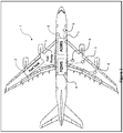
- FIG. 1 illustrates schematically an aircraft 1 having a fuel tank 2, a fuel pump 3, a Fuel Quantity Management System (FQMS) 4, an Air Data Inertial Reference System (ADIRS) 5 and various sensors 6 connected to the FQMS 4 and the ADIRS 5.
- FQMS Fuel Quantity Management System
- ADIRS Air Data Inertial Reference System
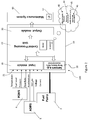
- FIG. 2 illustrates a schematic diagram of an aircraft fuel pump health monitoring system 100.
- the health monitoring system 100 includes a pump fault prediction unit 10 having an input module 20, a sensor group 30, a central processing unit, CPU, 40 and an output module 50; a maintenance system 60; the fuel pump 3; the FQMS 4; and the ADIRS 5.
- the maintenance system 60; the fuel pump 3, the FQMS 4 and the ADIRS 5 form part of the health monitoring system 100 but also stand alone and form part of other systems of the aircraft 1.
- the pump fault prediction unit 10 is capable of monitoring one fuel pump 3.
- the pump fault prediction unit 10 may be integrated within the fuel pump 3 itself but could alternatively be a self-contained unit mounted appropriately. Where not integrated with the fuel pump 3, the pump fault prediction unit 10 may provide a retro-fit solution for existing aircraft fuel pumps. Where the pump fault prediction unit 10 is integrated with the fuel pump 3 this may be used to replace an existing fuel pump 3, again as a retro-fit option. Alternatively the pump fault prediction unit 10 may form part of a new aircraft fuel system architecture.
- the FQMS 4, the ADIRS 5 and the maintenance system 60 of an existing aircraft design may be unaffected by the introduction of the pump fault prediction unit 10 to create the fuel pump health monitoring system 100.
- the input module 20 has an interface 21 including an environment sensor interface 21a for receiving input of a plurality of aircraft level signals.
- these aircraft level signals include fuel temperature, fuel level, fuel pressure and fuel flow rate from the FQMS 4; and aircraft accelerations in one or more dimensions, and aircraft attitude from the ADIRS 5.
- the 21 includes a pump sensor interface 21b which interfaces with the fuel pump 3, more particularly the controller of the fuel pump 3, to receive voltage and current signals from the pump controller. This list of inputs is not exhaustive and other aircraft level signals, pump signals, etc. may additionally or alternatively be received at the interface 21.
- the sensor group 30 includes additional sensors installed to monitor the fuel pump 3 and in the illustrated embodiment the sensor group 30 includes an accelerometer, a rate sensor to measure pitch/yaw/roll, and one or more temperature sensors.
- the sensor group 30 measures parameters of the fuel pump 3.
- the input module 20 and the sensor group 30 are connected by a two way data connection to the CPU 40.
- the CPU includes a computing element, e.g. a processor, random access memory, RAM, 41 and non-volatile memory 42.
- the memory 42 is adapted to store therein various data including:
- the CPU 40 is connected to output module 50 which is adapted to interface with the aircraft maintenance system 60 having a user interface, UI, 61.
- the maintenance system 60 is configured to receive a value for the Remaining Useful Life, RUL, for the fuel pump 3 from the pump fault prediction unit 10.
- the pump health monitoring system 100 in the illustrated embodiment receives inputs from the FQMS 4 and the ADIRS 5 and this arrangement is preferred since it makes use of existing sensing and monitoring equipment commonly found on existing aircraft making the installation of the pump fault prediction unit 10 relatively straightforward as a retro-fit option.
- the input module 20 may receive input of various aircraft level signals from dedicated aircraft level sensors so as to receive input of fuel temperature, fuel level, fuel pressure, fuel flow rate, aircraft accelerations, aircraft attitude, etc.
- Figure 3 illustrates a flow chart showing data capture of aircraft environment and pump life prediction. Steps 1 to 3 in Figure 3 refer to the health indicator capture and steps 4 to 6 relate to the RUL prediction.
- the set of instructions for steps 1 to 6 are stored in the memory 42 of the CPU 40 and also make use of the RAM 41 during processing of the steps.
- step 1 the aircraft environment 47 inside the fuel tank, more particularly parameters of the aircraft environment, are continuously checked.
- the aircraft environment 47 includes one or more environmental parameters selected from the group comprising: temperature, density, pressure, volume, or head of fuel in the fuel tank; flow rate of fuel through the fuel pump; aircraft attitude; aircraft acceleration in one or more dimensions; and fuel from acceleration in one or more dimensions.
- These environmental parameters are received at the environment sensor interface 21 a of the input module 20, as described above with reference to Figure 2 .
- These environmental parameters describe the environment the fuel pump 3 is exposed to which have been determined to affect the integrity of the pump health indicator.
- These environmental parameters are not exhaustive and other environmental parameters may additionally or alternatively form part of the aircraft environment 47 which is evaluated.
- the aircraft environment 47 is continuously checked. This continuous checking may refer to either a time based interval sampling of the aircraft environment 47 for either all or part of the time when the aircraft is switched on, or may refer to uninterrupted reading of the aircraft environment 47 from the moment the aircraft is switched on until the moment the aircraft is switched off.
- the read aircraft environment 47 is compared at step 1 to the reference environment 44 stored in the memory 42.
- the reference environment 44 contains a predetermined reference value for one or more of the environmental parameters corresponding to an in-flight condition for the aircraft fuel pump 3.
- the reference environment is predetermined in the sense that it comprises a value of the one or more reference environment parameters determined through off-line testing under controlled conditions, e.g. from laboratory experiment, which are pre-stored in the memory 42 and are not updated during use of the pump health monitoring system 100.
- the parameters of the reference environment 44 may be updated and revised as necessary through a software or firmware update when the pump health monitoring system is off-line, the parameters of the reference environment 44 are not updated during normal use of the pump health monitoring system 100.
- the selection of one or more of the parameters of the reference environment 44 corresponds to the same number of parameters of the aircraft environment 47 which are received via the environment sensor interface 21a. That does not mean that the environment sensor interface 21a receives only that same number of aircraft environment parameters, e.g. from the FQMS 4 and the ADIRS 5, but that the pump fault prediction unit 10 only reads the same number of aircraft environment parameters which correspond to the reference environment 44. It will be appreciated that different pump fault prediction units 10 may handle a greater or fewer number of parameters of the reference environment 44 as desired.
- step 1 once the read values of the parameters of the aircraft environment 47 are compared to the stored values of those parameters in the reference environment 44, if all of the read values of the parameters of the aircraft environment 47 do not match all of the values of the parameters of the reference environment 44 then no sample pump health indicator is captured.
- the parameter values in the reference environment 44 may be a single set of values but more likely are a set of parameter values each with a respective tolerance band, or the set of parameter values in the reference environment 44 may be a range of values for each parameter with upper and lower limits.
- the pump sensor interface 21b receives the value of one or more pump parameters selected from the group comprising: voltage, current, frequency and torque of the fuel pump 3.
- the fuel pump 3 will include an electric motor and signals from the controller of the fuel pump 3 can be used to provide the voltage, current or frequency of the electrical input to the electrical motor of the fuel pump 3.
- the rotating parts of the motor also can provide signals to the controller of the fuel pump 3 of the rotor torque or frequency which again may be selected as the one or more pump parameter signals received at the pump sensor interface 21b of the input module 20.
- step 2 a data set of instantaneous values including the one or more pump parameters 31 and the one or more environmental parameters 47 is captured as a health indicator 32.
- the captured health indicator 32 includes the instantaneously read aircraft environment parameters 47 and the instantaneously captured pump data 31.
- the pump data 31 may additionally include parameter values from the dedicated fuel pump sensor group 30 providing parameter values of the fuel pump temperature, accelerations, etc.
- correction factor 33 is applied at step 3.
- the correction factor 33 is applied to the captured data set 32 to account for any differences between the predetermined reference environment parameter values 44 and the read aircraft environment parameter values 47, bearing in mind that the read aircraft environment parameter values 47 may not match exactly with the reference environment parameter values 44 but nevertheless are within the tolerance band or range of parameter values acceptable for the condition matching at step 1.
- the correction factor 33 applied to the captured data set 32 is based on testing of the fuel pump 3 under controlled conditions, e.g. in a laboratory environment, and may be derived from fuel pump manufacturer's data or other sources. Once the correction factor 33 has been applied to the captured health indicator 32 an adjusted health indicator 43 is stored in memory 42 and made available to the prediction mechanism to project the RUL of the fuel pump 33.
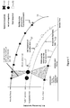
- the prediction steps 4 to 6 for computing the RUL will now be described with reference to Figure 4 which illustrates a chart showing the pump RUL versus sample time degradation paths.
- the prediction mechanism uses the health indicator of an ideal and worst case pump operation, in order to create baseline pump health indicators.
- the ideal or "healthy pump” baseline 51 and the worst case “failure limit” baseline 52 are created from baseline snapshots 53 from laboratory tests of the fuel pump 3 under controlled conditions.
- the ideal baseline provides a health indicator for ideal degradation of the pump at a given sample time.
- the worst case baseline 52 is a health indicator when a failure or degradation exists at a sample time.
- the baseline pump health indicators for ideal and failure conditions, 51, 52 are stored in the memory 42.
- the memory 42 also stores a reference line of the acceptable operating limit 54 for the fuel pump 3.
- the adjusted health indicators 43 are plotted as actual snapshots 55 and form a fault trajectory on the chart of remaining useful life RUL versus sample time.
- one previous actual snapshot 55 of an adjusted health indicator 43 is plotted and carries the number '1' whilst the current adjusted health indicator 43 is plotted as actual snapshot 55 with the number '2'.
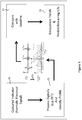
- step 4 of the prediction mechanism describes the processing of the adjusted health indicator 43 by comparison with the baseline ideal indicator 45a and the baseline worst case indicator 45b. This is done by a mapping technique, which may be selected from a variety of known mapping techniques, and which is generally described in Figure 5 .
- a captured indicator 70 e.g. an electrical signal
- 71 e.g. by Fast Fourier Transform
- This profile is then compared with a baseline 72 which is used to extrapolate trends and predict remaining life, 73.
- This mapping technique is illustrated graphically in the chart of Figure 4 by the shaded triangles which show the baseline comparison 72 (the comparison with the baseline snapshots 53) in order to compute the actual snapshot 55 with the number '2', which is an assessment of the present health of the fuel pump at step 5 of the prediction mechanism.
- step 6 the present health assessment of step 5 and past health assessments 46 are used to extrapolate trends and predict next snapshots 56 which build to form a full life trajectory of sample data 57.
- the trajectory of health decay 57 is created based on observed trends of captured health compared with the sample time.
- the evaluation of the present health is turned to a unit, the RUL 59, of the fuel pump 3.
- the RUL 59 is pushed through to the output module 50 of the pump fault prediction unit 10.
- the pump health monitoring system 100 also includes the maintenance system 61 having user interface 61.
- the RUL 59 is communicated from the output module 50 of the pump fault prediction unit 10 to the maintenance system 60 which displays the RUL 59 to a user (pilot, maintenance engineer, etc.) via the user interface 61. In the event that the RUL 59 is below a threshold, imminent pump failure is indicated via interface 61.
- the invention enables the creation of health assessments during flight under transient environments and attempts to find faults and create life predictions, thus generating an estimated time to failure. Operators will gain an accurate indication of when a pump should be replaced, saving money on aircraft otherwise potentially becoming grounded in a guest airport.
- the process uses baseline data collected under controlled conditions, which ensures high integrity for health monitoring.
Landscapes
- Engineering & Computer Science (AREA)
- Mechanical Engineering (AREA)
- General Engineering & Computer Science (AREA)
- Aviation & Aerospace Engineering (AREA)
- Manufacturing & Machinery (AREA)
- Transportation (AREA)
- Computer Hardware Design (AREA)
- Chemical & Material Sciences (AREA)
- Combustion & Propulsion (AREA)
- Physics & Mathematics (AREA)
- General Physics & Mathematics (AREA)
- Testing Of Devices, Machine Parts, Or Other Structures Thereof (AREA)
Applications Claiming Priority (1)
| Application Number | Priority Date | Filing Date | Title |
|---|---|---|---|
| GB1515114.5A GB2541682B (en) | 2015-08-25 | 2015-08-25 | Pump health monitoring |
Publications (2)
| Publication Number | Publication Date |
|---|---|
| EP3135911A1 true EP3135911A1 (fr) | 2017-03-01 |
| EP3135911B1 EP3135911B1 (fr) | 2018-05-02 |
Family
ID=54292191
Family Applications (1)
| Application Number | Title | Priority Date | Filing Date |
|---|---|---|---|
| EP16183430.4A Active EP3135911B1 (fr) | 2015-08-25 | 2016-08-09 | Surveillance de pompe médicale |
Country Status (3)
| Country | Link |
|---|---|
| US (1) | US10160553B2 (fr) |
| EP (1) | EP3135911B1 (fr) |
| GB (1) | GB2541682B (fr) |
Cited By (5)
| Publication number | Priority date | Publication date | Assignee | Title |
|---|---|---|---|---|
| USD890211S1 (en) | 2018-01-11 | 2020-07-14 | Wayne/Scott Fetzer Company | Pump components |
| US10711788B2 (en) | 2015-12-17 | 2020-07-14 | Wayne/Scott Fetzer Company | Integrated sump pump controller with status notifications |
| EP3693822A1 (fr) * | 2019-02-08 | 2020-08-12 | Simmonds Precision Products, Inc. | Surveillance de caractéristique d'entrée électrique pour gérer l'état d'un composant |
| USD893552S1 (en) | 2017-06-21 | 2020-08-18 | Wayne/Scott Fetzer Company | Pump components |
| CN113984427A (zh) * | 2021-11-26 | 2022-01-28 | 安徽农业大学 | 一种智能离心式双泵一体化泵站试验装置 |
Families Citing this family (15)
| Publication number | Priority date | Publication date | Assignee | Title |
|---|---|---|---|---|
| DE102014216230A1 (de) * | 2014-08-14 | 2016-02-18 | Continental Teves Ag & Co. Ohg | Verfahren zur Bestimmung einer Position und/oder Lageveränderung einer Hydraulikpumpe eines Kraftfahrzeugbremssystems sowie Kraftfahrzeugbremssystem |
| US10287986B2 (en) | 2016-07-29 | 2019-05-14 | United Technologies Corporation | Gas turbine engine fuel system prognostic algorithm |
| US10428744B2 (en) * | 2016-08-15 | 2019-10-01 | Hamilton Sundstrand Corporation | Fuel pump health detection |
| US11054342B2 (en) | 2017-02-20 | 2021-07-06 | Lifewhere, Llc | System for abnormal condition detection using nearest neighbor |
| GB2564136B (en) * | 2017-07-04 | 2020-01-22 | Ge Aviat Systems Ltd | Method and system for determining degradation in performance of an electronic device connected to a communication network |
| KR102316463B1 (ko) * | 2019-06-25 | 2021-10-22 | (주)아이티공간 | 제어 출력신호를 통한 기기의 건전성 지수 검출방법 |
| US10982612B1 (en) * | 2019-12-13 | 2021-04-20 | Caterpillar Inc. | Pump life prediction system |
| US11326590B2 (en) * | 2020-01-08 | 2022-05-10 | GM Global Technology Operations LLC | Method and apparatus for controlling a variable displacement pump |
| US12497963B2 (en) * | 2021-03-03 | 2025-12-16 | Ghsp, Inc. | Control system for a smart pump located within a lubrication/cooling assembly |
| CN113074122B (zh) * | 2021-03-31 | 2022-04-29 | 中国核动力研究设计院 | 一种对反应堆轴封泵振动监测的故障时刻预测方法 |
| JP2024001548A (ja) * | 2022-06-22 | 2024-01-10 | 株式会社荏原製作所 | ロケットエンジン用のポンプ装置のための状態監視システムおよびプログラム、並びに状態監視システムを用いたロケットエンジン用のポンプ装置の監視方法 |
| CN115387994B (zh) * | 2022-08-19 | 2026-01-09 | 中铁工程装备集团有限公司 | 液压泵组运行状态监测方法及系统 |
| CN115585066A (zh) * | 2022-11-01 | 2023-01-10 | 中国航空工业集团公司金城南京机电液压工程研究中心 | 一种集成化智能燃油泵及其控制方法 |
| EP4572131A1 (fr) * | 2023-12-15 | 2025-06-18 | Eaton Intelligent Power Limited | Détection de défaillance de moteur et prédiction de durée de vie utile restante |
| CN120592857B (zh) * | 2025-08-06 | 2025-10-03 | 上海云遥科技有限公司 | 一种多水泵并联协同控制方法和系统 |
Citations (7)
| Publication number | Priority date | Publication date | Assignee | Title |
|---|---|---|---|---|
| US20040199362A1 (en) * | 2003-03-13 | 2004-10-07 | An Cao | Intelligent modelling of process and tool health |
| EP1522731A2 (fr) * | 2003-10-11 | 2005-04-13 | Goodrich Control Systems Ltd | Surveillance de l'état d'une pompe |
| EP1801391A2 (fr) * | 2005-12-23 | 2007-06-27 | Rolls-Royce plc | Surveillance de l'état d'un système de carburant de moteur |
| EP1826408A2 (fr) * | 2006-02-22 | 2007-08-29 | Hamilton Sundstrand Corporation | Pompe de dosage avec auto-étalonnage et prédiction de l'état de santé |
| US20090249128A1 (en) * | 2008-03-30 | 2009-10-01 | Heckman Randy L | Predictive diagnostics system, apparatus, and method for improved reliability |
| EP2517957A2 (fr) * | 2011-04-28 | 2012-10-31 | Airbus Operations Limited | Système de ravitaillement en vol d'un aéronef |
| US20140039833A1 (en) * | 2012-07-31 | 2014-02-06 | Joseph Hiserodt Sharpe, JR. | Systems and methods to monitor an asset in an operating process unit |
Family Cites Families (9)
| Publication number | Priority date | Publication date | Assignee | Title |
|---|---|---|---|---|
| US6757665B1 (en) | 1999-09-28 | 2004-06-29 | Rockwell Automation Technologies, Inc. | Detection of pump cavitation/blockage and seal failure via current signature analysis |
| US6709240B1 (en) | 2002-11-13 | 2004-03-23 | Eaton Corporation | Method and apparatus of detecting low flow/cavitation in a centrifugal pump |
| US6941785B2 (en) | 2003-05-13 | 2005-09-13 | Ut-Battelle, Llc | Electric fuel pump condition monitor system using electrical signature analysis |
| US20090299535A1 (en) * | 2007-08-08 | 2009-12-03 | Honeywell International, Inc. | Electric motor driven lubrication pump and lubrication system prognostic and health management system and method |
| US9845012B2 (en) | 2011-07-06 | 2017-12-19 | General Electric Company | System and method for predicting mechanical failure of a motor |
| CN102416821A (zh) * | 2011-07-27 | 2012-04-18 | 中国国际航空股份有限公司 | 飞机系统数据处理方法 |
| FR3027386A1 (fr) * | 2014-10-21 | 2016-04-22 | Airbus Operations Sas | Procede et dispositif d'aide a la gestion de procedures, notamment de pannes de systemes d'un aeronef. |
| US9777723B2 (en) * | 2015-01-02 | 2017-10-03 | General Electric Company | System and method for health management of pumping system |
| US10125629B2 (en) * | 2016-07-29 | 2018-11-13 | United Technologies Corporation | Systems and methods for assessing the health of a first apparatus by monitoring a dependent second apparatus |
-
2015
- 2015-08-25 GB GB1515114.5A patent/GB2541682B/en active Active
-
2016
- 2016-08-09 EP EP16183430.4A patent/EP3135911B1/fr active Active
- 2016-08-25 US US15/246,946 patent/US10160553B2/en active Active
Patent Citations (7)
| Publication number | Priority date | Publication date | Assignee | Title |
|---|---|---|---|---|
| US20040199362A1 (en) * | 2003-03-13 | 2004-10-07 | An Cao | Intelligent modelling of process and tool health |
| EP1522731A2 (fr) * | 2003-10-11 | 2005-04-13 | Goodrich Control Systems Ltd | Surveillance de l'état d'une pompe |
| EP1801391A2 (fr) * | 2005-12-23 | 2007-06-27 | Rolls-Royce plc | Surveillance de l'état d'un système de carburant de moteur |
| EP1826408A2 (fr) * | 2006-02-22 | 2007-08-29 | Hamilton Sundstrand Corporation | Pompe de dosage avec auto-étalonnage et prédiction de l'état de santé |
| US20090249128A1 (en) * | 2008-03-30 | 2009-10-01 | Heckman Randy L | Predictive diagnostics system, apparatus, and method for improved reliability |
| EP2517957A2 (fr) * | 2011-04-28 | 2012-10-31 | Airbus Operations Limited | Système de ravitaillement en vol d'un aéronef |
| US20140039833A1 (en) * | 2012-07-31 | 2014-02-06 | Joseph Hiserodt Sharpe, JR. | Systems and methods to monitor an asset in an operating process unit |
Cited By (9)
| Publication number | Priority date | Publication date | Assignee | Title |
|---|---|---|---|---|
| US10711788B2 (en) | 2015-12-17 | 2020-07-14 | Wayne/Scott Fetzer Company | Integrated sump pump controller with status notifications |
| US11486401B2 (en) | 2015-12-17 | 2022-11-01 | Wayne/Scott Fetzer Company | Integrated sump pump controller with status notifications |
| USD893552S1 (en) | 2017-06-21 | 2020-08-18 | Wayne/Scott Fetzer Company | Pump components |
| USD1015378S1 (en) | 2017-06-21 | 2024-02-20 | Wayne/Scott Fetzer Company | Pump components |
| USD890211S1 (en) | 2018-01-11 | 2020-07-14 | Wayne/Scott Fetzer Company | Pump components |
| USD1014560S1 (en) | 2018-01-11 | 2024-02-13 | Wayne/Scott Fetzer Company | Pump components |
| EP3693822A1 (fr) * | 2019-02-08 | 2020-08-12 | Simmonds Precision Products, Inc. | Surveillance de caractéristique d'entrée électrique pour gérer l'état d'un composant |
| CN113984427A (zh) * | 2021-11-26 | 2022-01-28 | 安徽农业大学 | 一种智能离心式双泵一体化泵站试验装置 |
| CN113984427B (zh) * | 2021-11-26 | 2022-07-29 | 安徽农业大学 | 一种智能离心式双泵一体化泵站试验装置 |
Also Published As
| Publication number | Publication date |
|---|---|
| GB2541682A (en) | 2017-03-01 |
| US10160553B2 (en) | 2018-12-25 |
| US20170057667A1 (en) | 2017-03-02 |
| GB201515114D0 (en) | 2015-10-07 |
| GB2541682B (en) | 2017-09-06 |
| EP3135911B1 (fr) | 2018-05-02 |
Similar Documents
| Publication | Publication Date | Title |
|---|---|---|
| EP3135911B1 (fr) | Surveillance de pompe médicale | |
| US8401760B2 (en) | Gas turbine engine oil consumption monitoring system and method | |
| US8321118B2 (en) | Operations support systems and methods with power assurance | |
| EP2202147B1 (fr) | Systèmes de support d'opérations et procédés de gestion de puissance | |
| US8744651B2 (en) | Method of determining a maneuver performed by an aircraft | |
| EP2207072A2 (fr) | Systèmes de support d'opérations et procédés avec diagnostic de moteur | |
| JP4482206B2 (ja) | 埋込みエンジン診断システム | |
| US8371533B2 (en) | Aircraft auxiliary fuel tank system and method | |
| KR20150012219A (ko) | 엔진 윤활유 모니터링 시스템 및 방법 | |
| EP3173882A1 (fr) | Procédé de détection de consommation d'huile en temps réel | |
| CN105473921B (zh) | 用于对航空器发动机的阀进行监控的方法 | |
| CN110131050B (zh) | 用于交通工具控制系统的虚拟化数据 | |
| US10551818B2 (en) | Fault detection methods and systems | |
| US7801695B2 (en) | Operations support systems and methods with model-based torque estimates | |
| US10458322B2 (en) | Surge determination device, surge determination method, and program | |
| US8825278B2 (en) | System for detecting the first signs of a malfunction of an aircraft engine valve | |
| US20220242592A1 (en) | System and method for monitoring an aircraft engine | |
| CN104343491A (zh) | 一种发动机滑油添加探测系统及方法 | |
| US20170073064A1 (en) | Rotor system structural fault estimation | |
| EP3399155B1 (fr) | Procédé et système pour prendre en compte la perte d'un signal de couple | |
| GB2529637A (en) | System for building and deploying inference model | |
| CN121720553A (zh) | 一种飞机燃油标定方法、装置、设备及介质 | |
| US11280232B2 (en) | System and method for monitoring engine fluid levels | |
| CN121854249A (zh) | 一种航空涡轴发动机燃油压力监控方法及装置 |
Legal Events
| Date | Code | Title | Description |
|---|---|---|---|
| PUAI | Public reference made under article 153(3) epc to a published international application that has entered the european phase |
Free format text: ORIGINAL CODE: 0009012 |
|
| STAA | Information on the status of an ep patent application or granted ep patent |
Free format text: STATUS: THE APPLICATION HAS BEEN PUBLISHED |
|
| AK | Designated contracting states |
Kind code of ref document: A1 Designated state(s): AL AT BE BG CH CY CZ DE DK EE ES FI FR GB GR HR HU IE IS IT LI LT LU LV MC MK MT NL NO PL PT RO RS SE SI SK SM TR |
|
| AX | Request for extension of the european patent |
Extension state: BA ME |
|
| STAA | Information on the status of an ep patent application or granted ep patent |
Free format text: STATUS: REQUEST FOR EXAMINATION WAS MADE |
|
| 17P | Request for examination filed |
Effective date: 20170706 |
|
| RBV | Designated contracting states (corrected) |
Designated state(s): AL AT BE BG CH CY CZ DE DK EE ES FI FR GB GR HR HU IE IS IT LI LT LU LV MC MK MT NL NO PL PT RO RS SE SI SK SM TR |
|
| GRAP | Despatch of communication of intention to grant a patent |
Free format text: ORIGINAL CODE: EPIDOSNIGR1 |
|
| STAA | Information on the status of an ep patent application or granted ep patent |
Free format text: STATUS: GRANT OF PATENT IS INTENDED |
|
| INTG | Intention to grant announced |
Effective date: 20171107 |
|
| GRAS | Grant fee paid |
Free format text: ORIGINAL CODE: EPIDOSNIGR3 |
|
| GRAA | (expected) grant |
Free format text: ORIGINAL CODE: 0009210 |
|
| STAA | Information on the status of an ep patent application or granted ep patent |
Free format text: STATUS: THE PATENT HAS BEEN GRANTED |
|
| AK | Designated contracting states |
Kind code of ref document: B1 Designated state(s): AL AT BE BG CH CY CZ DE DK EE ES FI FR GB GR HR HU IE IS IT LI LT LU LV MC MK MT NL NO PL PT RO RS SE SI SK SM TR |
|
| REG | Reference to a national code |
Ref country code: GB Ref legal event code: FG4D |
|
| REG | Reference to a national code |
Ref country code: CH Ref legal event code: EP Ref country code: AT Ref legal event code: REF Ref document number: 995555 Country of ref document: AT Kind code of ref document: T Effective date: 20180515 |
|
| REG | Reference to a national code |
Ref country code: DE Ref legal event code: R096 Ref document number: 602016002735 Country of ref document: DE Ref country code: IE Ref legal event code: FG4D |
|
| REG | Reference to a national code |
Ref country code: FR Ref legal event code: PLFP Year of fee payment: 3 |
|
| REG | Reference to a national code |
Ref country code: NL Ref legal event code: MP Effective date: 20180502 |
|
| REG | Reference to a national code |
Ref country code: LT Ref legal event code: MG4D |
|
| PG25 | Lapsed in a contracting state [announced via postgrant information from national office to epo] |
Ref country code: BG Free format text: LAPSE BECAUSE OF FAILURE TO SUBMIT A TRANSLATION OF THE DESCRIPTION OR TO PAY THE FEE WITHIN THE PRESCRIBED TIME-LIMIT Effective date: 20180802 Ref country code: LT Free format text: LAPSE BECAUSE OF FAILURE TO SUBMIT A TRANSLATION OF THE DESCRIPTION OR TO PAY THE FEE WITHIN THE PRESCRIBED TIME-LIMIT Effective date: 20180502 Ref country code: FI Free format text: LAPSE BECAUSE OF FAILURE TO SUBMIT A TRANSLATION OF THE DESCRIPTION OR TO PAY THE FEE WITHIN THE PRESCRIBED TIME-LIMIT Effective date: 20180502 Ref country code: ES Free format text: LAPSE BECAUSE OF FAILURE TO SUBMIT A TRANSLATION OF THE DESCRIPTION OR TO PAY THE FEE WITHIN THE PRESCRIBED TIME-LIMIT Effective date: 20180502 Ref country code: NO Free format text: LAPSE BECAUSE OF FAILURE TO SUBMIT A TRANSLATION OF THE DESCRIPTION OR TO PAY THE FEE WITHIN THE PRESCRIBED TIME-LIMIT Effective date: 20180802 Ref country code: SE Free format text: LAPSE BECAUSE OF FAILURE TO SUBMIT A TRANSLATION OF THE DESCRIPTION OR TO PAY THE FEE WITHIN THE PRESCRIBED TIME-LIMIT Effective date: 20180502 |
|
| PG25 | Lapsed in a contracting state [announced via postgrant information from national office to epo] |
Ref country code: RS Free format text: LAPSE BECAUSE OF FAILURE TO SUBMIT A TRANSLATION OF THE DESCRIPTION OR TO PAY THE FEE WITHIN THE PRESCRIBED TIME-LIMIT Effective date: 20180502 Ref country code: LV Free format text: LAPSE BECAUSE OF FAILURE TO SUBMIT A TRANSLATION OF THE DESCRIPTION OR TO PAY THE FEE WITHIN THE PRESCRIBED TIME-LIMIT Effective date: 20180502 Ref country code: HR Free format text: LAPSE BECAUSE OF FAILURE TO SUBMIT A TRANSLATION OF THE DESCRIPTION OR TO PAY THE FEE WITHIN THE PRESCRIBED TIME-LIMIT Effective date: 20180502 Ref country code: GR Free format text: LAPSE BECAUSE OF FAILURE TO SUBMIT A TRANSLATION OF THE DESCRIPTION OR TO PAY THE FEE WITHIN THE PRESCRIBED TIME-LIMIT Effective date: 20180803 Ref country code: NL Free format text: LAPSE BECAUSE OF FAILURE TO SUBMIT A TRANSLATION OF THE DESCRIPTION OR TO PAY THE FEE WITHIN THE PRESCRIBED TIME-LIMIT Effective date: 20180502 |
|
| REG | Reference to a national code |
Ref country code: AT Ref legal event code: MK05 Ref document number: 995555 Country of ref document: AT Kind code of ref document: T Effective date: 20180502 |
|
| PG25 | Lapsed in a contracting state [announced via postgrant information from national office to epo] |
Ref country code: SK Free format text: LAPSE BECAUSE OF FAILURE TO SUBMIT A TRANSLATION OF THE DESCRIPTION OR TO PAY THE FEE WITHIN THE PRESCRIBED TIME-LIMIT Effective date: 20180502 Ref country code: RO Free format text: LAPSE BECAUSE OF FAILURE TO SUBMIT A TRANSLATION OF THE DESCRIPTION OR TO PAY THE FEE WITHIN THE PRESCRIBED TIME-LIMIT Effective date: 20180502 Ref country code: PL Free format text: LAPSE BECAUSE OF FAILURE TO SUBMIT A TRANSLATION OF THE DESCRIPTION OR TO PAY THE FEE WITHIN THE PRESCRIBED TIME-LIMIT Effective date: 20180502 Ref country code: CZ Free format text: LAPSE BECAUSE OF FAILURE TO SUBMIT A TRANSLATION OF THE DESCRIPTION OR TO PAY THE FEE WITHIN THE PRESCRIBED TIME-LIMIT Effective date: 20180502 Ref country code: AT Free format text: LAPSE BECAUSE OF FAILURE TO SUBMIT A TRANSLATION OF THE DESCRIPTION OR TO PAY THE FEE WITHIN THE PRESCRIBED TIME-LIMIT Effective date: 20180502 Ref country code: EE Free format text: LAPSE BECAUSE OF FAILURE TO SUBMIT A TRANSLATION OF THE DESCRIPTION OR TO PAY THE FEE WITHIN THE PRESCRIBED TIME-LIMIT Effective date: 20180502 Ref country code: DK Free format text: LAPSE BECAUSE OF FAILURE TO SUBMIT A TRANSLATION OF THE DESCRIPTION OR TO PAY THE FEE WITHIN THE PRESCRIBED TIME-LIMIT Effective date: 20180502 |
|
| REG | Reference to a national code |
Ref country code: DE Ref legal event code: R097 Ref document number: 602016002735 Country of ref document: DE |
|
| PG25 | Lapsed in a contracting state [announced via postgrant information from national office to epo] |
Ref country code: IT Free format text: LAPSE BECAUSE OF FAILURE TO SUBMIT A TRANSLATION OF THE DESCRIPTION OR TO PAY THE FEE WITHIN THE PRESCRIBED TIME-LIMIT Effective date: 20180502 Ref country code: SM Free format text: LAPSE BECAUSE OF FAILURE TO SUBMIT A TRANSLATION OF THE DESCRIPTION OR TO PAY THE FEE WITHIN THE PRESCRIBED TIME-LIMIT Effective date: 20180502 |
|
| PLBE | No opposition filed within time limit |
Free format text: ORIGINAL CODE: 0009261 |
|
| STAA | Information on the status of an ep patent application or granted ep patent |
Free format text: STATUS: NO OPPOSITION FILED WITHIN TIME LIMIT |
|
| PG25 | Lapsed in a contracting state [announced via postgrant information from national office to epo] |
Ref country code: MC Free format text: LAPSE BECAUSE OF FAILURE TO SUBMIT A TRANSLATION OF THE DESCRIPTION OR TO PAY THE FEE WITHIN THE PRESCRIBED TIME-LIMIT Effective date: 20180502 |
|
| 26N | No opposition filed |
Effective date: 20190205 |
|
| PG25 | Lapsed in a contracting state [announced via postgrant information from national office to epo] |
Ref country code: LU Free format text: LAPSE BECAUSE OF NON-PAYMENT OF DUE FEES Effective date: 20180809 |
|
| REG | Reference to a national code |
Ref country code: BE Ref legal event code: MM Effective date: 20180831 |
|
| REG | Reference to a national code |
Ref country code: IE Ref legal event code: MM4A |
|
| PG25 | Lapsed in a contracting state [announced via postgrant information from national office to epo] |
Ref country code: SI Free format text: LAPSE BECAUSE OF FAILURE TO SUBMIT A TRANSLATION OF THE DESCRIPTION OR TO PAY THE FEE WITHIN THE PRESCRIBED TIME-LIMIT Effective date: 20180502 |
|
| PG25 | Lapsed in a contracting state [announced via postgrant information from national office to epo] |
Ref country code: IE Free format text: LAPSE BECAUSE OF NON-PAYMENT OF DUE FEES Effective date: 20180809 |
|
| PG25 | Lapsed in a contracting state [announced via postgrant information from national office to epo] |
Ref country code: BE Free format text: LAPSE BECAUSE OF NON-PAYMENT OF DUE FEES Effective date: 20180831 |
|
| PG25 | Lapsed in a contracting state [announced via postgrant information from national office to epo] |
Ref country code: AL Free format text: LAPSE BECAUSE OF FAILURE TO SUBMIT A TRANSLATION OF THE DESCRIPTION OR TO PAY THE FEE WITHIN THE PRESCRIBED TIME-LIMIT Effective date: 20180502 |
|
| PG25 | Lapsed in a contracting state [announced via postgrant information from national office to epo] |
Ref country code: MT Free format text: LAPSE BECAUSE OF NON-PAYMENT OF DUE FEES Effective date: 20180809 |
|
| PG25 | Lapsed in a contracting state [announced via postgrant information from national office to epo] |
Ref country code: TR Free format text: LAPSE BECAUSE OF FAILURE TO SUBMIT A TRANSLATION OF THE DESCRIPTION OR TO PAY THE FEE WITHIN THE PRESCRIBED TIME-LIMIT Effective date: 20180502 |
|
| PG25 | Lapsed in a contracting state [announced via postgrant information from national office to epo] |
Ref country code: LI Free format text: LAPSE BECAUSE OF NON-PAYMENT OF DUE FEES Effective date: 20190831 Ref country code: PT Free format text: LAPSE BECAUSE OF FAILURE TO SUBMIT A TRANSLATION OF THE DESCRIPTION OR TO PAY THE FEE WITHIN THE PRESCRIBED TIME-LIMIT Effective date: 20180502 Ref country code: CH Free format text: LAPSE BECAUSE OF NON-PAYMENT OF DUE FEES Effective date: 20190831 |
|
| PG25 | Lapsed in a contracting state [announced via postgrant information from national office to epo] |
Ref country code: MK Free format text: LAPSE BECAUSE OF NON-PAYMENT OF DUE FEES Effective date: 20180502 Ref country code: CY Free format text: LAPSE BECAUSE OF FAILURE TO SUBMIT A TRANSLATION OF THE DESCRIPTION OR TO PAY THE FEE WITHIN THE PRESCRIBED TIME-LIMIT Effective date: 20180502 Ref country code: HU Free format text: LAPSE BECAUSE OF FAILURE TO SUBMIT A TRANSLATION OF THE DESCRIPTION OR TO PAY THE FEE WITHIN THE PRESCRIBED TIME-LIMIT; INVALID AB INITIO Effective date: 20160809 |
|
| PG25 | Lapsed in a contracting state [announced via postgrant information from national office to epo] |
Ref country code: IS Free format text: LAPSE BECAUSE OF FAILURE TO SUBMIT A TRANSLATION OF THE DESCRIPTION OR TO PAY THE FEE WITHIN THE PRESCRIBED TIME-LIMIT Effective date: 20180902 |
|
| PGFP | Annual fee paid to national office [announced via postgrant information from national office to epo] |
Ref country code: DE Payment date: 20250820 Year of fee payment: 10 |
|
| PGFP | Annual fee paid to national office [announced via postgrant information from national office to epo] |
Ref country code: GB Payment date: 20250820 Year of fee payment: 10 |
|
| PGFP | Annual fee paid to national office [announced via postgrant information from national office to epo] |
Ref country code: FR Payment date: 20250829 Year of fee payment: 10 |