EP1826469A1 - Raccord de tuyaux - Google Patents
Raccord de tuyaux Download PDFInfo
- Publication number
- EP1826469A1 EP1826469A1 EP06003773A EP06003773A EP1826469A1 EP 1826469 A1 EP1826469 A1 EP 1826469A1 EP 06003773 A EP06003773 A EP 06003773A EP 06003773 A EP06003773 A EP 06003773A EP 1826469 A1 EP1826469 A1 EP 1826469A1
- Authority
- EP
- European Patent Office
- Prior art keywords
- pipe connector
- connector according
- outer layer
- inner layer
- seal
- Prior art date
- Legal status (The legal status is an assumption and is not a legal conclusion. Google has not performed a legal analysis and makes no representation as to the accuracy of the status listed.)
- Withdrawn
Links
Images


Classifications
-
- F—MECHANICAL ENGINEERING; LIGHTING; HEATING; WEAPONS; BLASTING
- F16—ENGINEERING ELEMENTS AND UNITS; GENERAL MEASURES FOR PRODUCING AND MAINTAINING EFFECTIVE FUNCTIONING OF MACHINES OR INSTALLATIONS; THERMAL INSULATION IN GENERAL
- F16L—PIPES; JOINTS OR FITTINGS FOR PIPES; SUPPORTS FOR PIPES, CABLES OR PROTECTIVE TUBING; MEANS FOR THERMAL INSULATION IN GENERAL
- F16L21/00—Joints with sleeve or socket
- F16L21/06—Joints with sleeve or socket with a divided sleeve or ring clamping around the pipe ends
- F16L21/065—Joints with sleeve or socket with a divided sleeve or ring clamping around the pipe ends tightened by tangentially-arranged threaded pins
-
- F—MECHANICAL ENGINEERING; LIGHTING; HEATING; WEAPONS; BLASTING
- F16—ENGINEERING ELEMENTS AND UNITS; GENERAL MEASURES FOR PRODUCING AND MAINTAINING EFFECTIVE FUNCTIONING OF MACHINES OR INSTALLATIONS; THERMAL INSULATION IN GENERAL
- F16L—PIPES; JOINTS OR FITTINGS FOR PIPES; SUPPORTS FOR PIPES, CABLES OR PROTECTIVE TUBING; MEANS FOR THERMAL INSULATION IN GENERAL
- F16L21/00—Joints with sleeve or socket
- F16L21/002—Sleeves or nipples for pipes of the same diameter; Reduction pieces
- F16L21/005—Sleeves or nipples for pipes of the same diameter; Reduction pieces made of elastic material, e.g. partly or completely surrounded by clamping devices
-
- F—MECHANICAL ENGINEERING; LIGHTING; HEATING; WEAPONS; BLASTING
- F01—MACHINES OR ENGINES IN GENERAL; ENGINE PLANTS IN GENERAL; STEAM ENGINES
- F01N—GAS-FLOW SILENCERS OR EXHAUST APPARATUS FOR MACHINES OR ENGINES IN GENERAL; GAS-FLOW SILENCERS OR EXHAUST APPARATUS FOR INTERNAL-COMBUSTION ENGINES
- F01N13/00—Exhaust or silencing apparatus characterised by constructional features
- F01N13/18—Construction facilitating manufacture, assembly, or disassembly
- F01N13/1805—Fixing exhaust manifolds, exhaust pipes or pipe sections to each other, to engine or to vehicle body
Definitions
- the invention relates to a pipe connector for connecting two pipe ends, comprising an outer layer which encloses at least one inner layer, wherein the inner layer can be acted upon by the outer layer in the radial direction of force.
- pipes must be connected, which have different outer diameter.
- the generic pipe connector therefore requires a complex assembly, which is extremely error prone.
- the result of this are pipe joints, which have leaks or can form them at least during operation of the pipe joint.
- the invention is therefore based on the object to provide a pipe connector, which ensures proper operation of a pipe connection after simple installation.
- a pipe connector of the type mentioned above is characterized in that the inner or outer layer are assigned means for limiting the application of force to the inner layer.
- means for limiting the radial application of force to the inner layer ensure that the inner layer can be applied sealingly to tubes of different outer diameters.
- the means ensure that the fitter can act on the outer layer in the radial direction with any force and the inner layer is still not applied to a certain extent with force.
- the fitter so firmly attach the outer layer to the respective pipe ends that they remain rigidly connected to each other in the region of the pipe joint in vibration or relative movements.
- movements of the interconnected pipes are derived in downstream, vibration damping devices.
- the means could be arranged in the region of openings for receiving pipe ends.
- This concrete embodiment ensures that the means can rest directly on the jacket of the pipe and the pipe can thus act as an abutment.
- the means could be designed projecting in the radial direction inwardly. This ensures that the means can establish a minimum distance between the inner wall of the outer layer and the outer surface of a pipe.
- the means are configured incompressible, wherein the inner layer is designed to be compressible at least in some areas and to that extent itself could be designed as a seal. It is conceivable that the inner layer is only deformed to a certain extent during pressing against the pipe jacket, namely until the means come to the stop on the pipe jacket and prevent further compression of the inner layer or seal.
- the means could be configured as elements having a greater thickness than the inner layer.
- a radially encircling hollow gap is created between the inner layer and the outer layer, in which a seal can be inserted.
- the seal may overlap two pipe ends of different outside diameter and be compressed to a maximum of the height of the gap.
- the funds could be designed in this background as strip-shaped layers.
- the strip-shaped layers can be easily manufactured and assembled. It is conceivable that the inner layer is inserted between the strip-shaped layers. Concretely, the inner layer could for example have a thickness of 0.6 mm and each strip could, for example, have a thickness of 1 mm. In this specific embodiment, a seal resting on the inner layer would be compressible to 0.4 mm.
- the inner layer and the strip-shaped means could be made of metal, preferably stainless steel or spring steel, since these materials are sufficiently ductile to compensate for any unevenness of the tube shell.
- the funds could be determined area by area on the outer layers.
- This specific embodiment allows a slight movement of the means relative to the outer layer when pulled together. As a result, damage to the inner layer or a possibly inserted seal can be avoided.
- strip-shaped layers are applied to the inner circumference of a cylindrical sleeve in such a way that the ends of the strip-shaped layers define a gap. Such a gap can be closed when contracting an optionally longitudinally slotted outer sleeve or outer layer, so that the ends of the strip-shaped layers approach each other and the strip-shaped layers can firmly grasp the tube shells.
- the inner layer could be formed as a strip with a projecting portion for receiving in a recess which is also formed in the inner layer.
- the projecting portion could be trapezoidal and insertable into a complementary thereto formed recess. As a result, a centering of the inner layer is ensured when contraction of the outer layer.
- the projecting portion could be slightly wider in regions than the clear width of the recess to prevent the inner layer is reduced over a certain amount in its radial extent.
- the inner layer could surround a seal. This design ensures that the seal is not directly applied by the outer layer with force. Furthermore, by the provision of an inner layer between outer layer and seal, a recess or recesses in the shell of the outer layer can be covered to effect a seal.
- the seal could be made of graphite. Graphite shows a temperature resistance of up to 500 ° C when oxygen is added to a hot gas stream. Against this background, it is conceivable that the gasket has two layers of graphite which sandwich a metallic foil, for example with a thickness of 0.05 mm. The metallic foil stabilizes the seal. The seal could include mica. Such a seal shows high usability even at temperatures of 1200 ° C. When using the seals described here, the pipe connector in the exhaust system of a motor vehicle is easily used.
- the seal could have recesses.
- the provision of recesses ensures that the gasket does not wrinkle upon contracting the outer layer and changing its radial extent forms. Wrinkling can lead to leaks and reduce the life of the seal.
- the seal has elevations at least in some areas.
- the surveys could be configured, for example, as ribbing or grooving. It is also conceivable punctual surveys. This specific embodiment ensures that unevenness can be compensated for on the jacket of the tube.
- the elevations may, for example, be designed in a zig-zag shape in cross-section. By this configuration, a line seal in the region of the tips of the zigzag-shaped configuration is possible.
- the outer layer could be formed as a sleeve.
- This specific embodiment allows a full-surface environment of the inner layer and the means for limiting the application of force.
- the sleeve has a thickness of 0.6 mm, for example. Such a thickness has proven to be advantageous to compensate for an investment in pipes of different outer diameter.
- the sleeve preferably has a slot in the longitudinal direction, which is closed when the sleeve is pulled together or reduced in its extent.
- the slot could also be designed in a labyrinth-like manner in order to favor a bearing of the sleeve on tubes of different outer diameters.
- the outer layer could have regions of different material thickness in the circumferential direction. This embodiment allows the formation of two regions of the outer layer, which are almost independently variable to varying degrees in their radial extent.
- the outer layer is so far more easily reducible at one end in their radial extent than at the other end.
- the outer layer has recesses, in particular a slot, in the circumferential direction.
- the outer layer could be associated with a clamping device.
- the provision of a tensioning device allows the application of force to the outer sleeve and a reduction in its radial extent.
- the tensioning device could have a claw, which encompasses flange regions of the outer layer. Against this background, it is conceivable that the flange regions delimit a tapering gap. By closing this gap, the outer layer can be very metered and defined acted upon with force.
- the tensioning device could comprise a clip connection. Such a connection allows a quick installation.
- the clamping device could have screws that engage in threads that are directly associated with the outer layer. This specific embodiment allows a very compact and space-saving design of the pipe connector, since the measure of the protruding from the outer shell of the outer shell elements is determined only by the dimension of the thread.
- the outer layer could be associated in the longitudinal direction with elongate sleeves having threaded passages. In these passages screws could be screwed. As a result, only by tightening the screws, the radial extent of the outer sleeve can be changed.
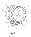
- the inner layer 2 is kraftbeaufschlagbar by the outer layer 1 in the radial direction.
- the inner layer 2 or the outer layer 1 are associated with means 3 for limiting the application of force to the inner layer 2
- the means 3 are arranged in the region of the openings 4a, 4b, for receiving pipe ends.
- the means 3 are projecting in the radial direction designed.
- the means 3 protrude in the radial direction in the direction of the longitudinal axis of the pipe connector.
- the means 3 are designed as elements which have a greater thickness than the inner layer 2.
- the means 3 are configured as strip-shaped layers 3, which are defined in regions on the outer layer 1. The determination is carried out by welding points at one end of the strip-shaped layers 3. The other end and the rest of the strip-shaped layers 3 are free to move.
- the layers 3 define by their ends a gap 3a, which can be reduced by approaching the ends in its extension.
- the outer layer 1 is made of a metallic material.
- the means 3 and the inner layer 2 are also made of a metallic material. Stainless steel is used as the metallic material.
- the inner layer 2 is formed as a strip with a projecting portion for receiving in a recess.
- the recess is also formed in the inner layer 2.
- the projecting portion is configured analogously to the projecting portion 18 of the seal 5 according to FIG. 3.
- the recess is also analogous to the recess 17 of the seal 5 according to FIG. 3 configured.
- the projecting portion and the recess cause a centering of the inner layer. 2
- the inner layer 2 surrounds a seal 5, which is designed as a graphite seal.
- the outer layer 1 is formed as a cylindrical sleeve 1, which may have a thickness of, for example, 0.6 mm.
- the outer layer 1 has a region 6 in the circumferential direction with a material thickness which is lower is the material thickness in the region of the openings 4a, 4b.
- the area 6 is formed as a slot.
- the outer layer 1 is associated with a clamping device 7 in the longitudinal direction in the region of a slot 1a.
- the tensioning device 7 comprises elongated sleeves 8, which are provided with passages 9, into which screws 10 can be screwed.
- Fig. 2 shows a clamping device 7 with flange portions 11 and 12, which define a tapered gap 1 b.
- the flange portions 11, 12 are assigned to the outer layer 1.
- the flange portions 11, 12 have fold areas, which are formed by a fold.
- pedestals 13, 14 are formed, on which a claw 15a, 15b can be applied.
- the base 14 prevent the direct contact of the claw 15a, 15b on the outer layer 1. As a result, the layer 1 is not damaged.
- the claw 15a, 15b and the flanges 11, 12 have passages through which screws 10 can be passed.
- Fig. 3 shows a seal 5 with recesses 16 which are intended to prevent the seal 5 tends to wrinkle.
- the seal 5 has at its one end a recess of trapezoidal configuration 17. At its other end, the seal 5 on a projecting portion 18, which is also designed trapezoidal.
- the configuration of the recess 17 and the projecting portion 18 is also realized in the inner layer 2 and serves to center them when bringing the ends of the inner layer 2. The effect of centering takes place naturally also when merging the seal 5.
- the inner layer 2 is provided with recesses which correspond to those of the seal 5.
- the seal 5 may for example have a width of 48 mm.
- the seal 5 may be configured as a soft-material seal, for example as a graphite seal.
Landscapes
- Engineering & Computer Science (AREA)
- General Engineering & Computer Science (AREA)
- Mechanical Engineering (AREA)
- Rigid Pipes And Flexible Pipes (AREA)
- Joints Allowing Movement (AREA)
Priority Applications (2)
| Application Number | Priority Date | Filing Date | Title |
|---|---|---|---|
| EP06003773A EP1826469A1 (fr) | 2006-02-24 | 2006-02-24 | Raccord de tuyaux |
| DE200620020460 DE202006020460U1 (de) | 2006-02-24 | 2006-02-24 | Rohrverbinder |
Applications Claiming Priority (1)
| Application Number | Priority Date | Filing Date | Title |
|---|---|---|---|
| EP06003773A EP1826469A1 (fr) | 2006-02-24 | 2006-02-24 | Raccord de tuyaux |
Publications (1)
| Publication Number | Publication Date |
|---|---|
| EP1826469A1 true EP1826469A1 (fr) | 2007-08-29 |
Family
ID=36694378
Family Applications (1)
| Application Number | Title | Priority Date | Filing Date |
|---|---|---|---|
| EP06003773A Withdrawn EP1826469A1 (fr) | 2006-02-24 | 2006-02-24 | Raccord de tuyaux |
Country Status (2)
| Country | Link |
|---|---|
| EP (1) | EP1826469A1 (fr) |
| DE (1) | DE202006020460U1 (fr) |
Families Citing this family (1)
| Publication number | Priority date | Publication date | Assignee | Title |
|---|---|---|---|---|
| DE102012021485B4 (de) * | 2012-11-05 | 2015-07-23 | Gennicoo GmbH | Einrichtung zur Verbindung von Rohrenden |
Citations (4)
| Publication number | Priority date | Publication date | Assignee | Title |
|---|---|---|---|---|
| US3004781A (en) * | 1959-01-29 | 1961-10-17 | Jolly L Morris | Slotted shell coupling clamp |
| US4119333A (en) * | 1976-07-21 | 1978-10-10 | Immanuel Straub | Pipe coupling |
| US5104159A (en) * | 1990-01-11 | 1992-04-14 | Kyukichi Sugiyama | Threadless coupling for pipes and an air-tight inner cylinder therefor |
| DE20210323U1 (de) | 2002-07-04 | 2002-09-26 | HJS Fahrzeugtechnik GmbH & Co., 58706 Menden | Rohrverbinder |
-
2006
- 2006-02-24 DE DE200620020460 patent/DE202006020460U1/de not_active Expired - Lifetime
- 2006-02-24 EP EP06003773A patent/EP1826469A1/fr not_active Withdrawn
Patent Citations (4)
| Publication number | Priority date | Publication date | Assignee | Title |
|---|---|---|---|---|
| US3004781A (en) * | 1959-01-29 | 1961-10-17 | Jolly L Morris | Slotted shell coupling clamp |
| US4119333A (en) * | 1976-07-21 | 1978-10-10 | Immanuel Straub | Pipe coupling |
| US5104159A (en) * | 1990-01-11 | 1992-04-14 | Kyukichi Sugiyama | Threadless coupling for pipes and an air-tight inner cylinder therefor |
| DE20210323U1 (de) | 2002-07-04 | 2002-09-26 | HJS Fahrzeugtechnik GmbH & Co., 58706 Menden | Rohrverbinder |
Also Published As
| Publication number | Publication date |
|---|---|
| DE202006020460U1 (de) | 2008-08-14 |
Similar Documents
| Publication | Publication Date | Title |
|---|---|---|
| DE3014128A1 (de) | Verfahren zur herstellung einer rohrverbindung sowie rohrverbindung | |
| DE19609257A1 (de) | Rohrverbindung | |
| EP1647754A2 (fr) | Raccordement de deux conduits et bague d'étanchéité pour le raccordement | |
| EP3093545B1 (fr) | Agencement destine a relier deux extremites de tuyaux, en particulier deux extremites de tuyau disposees dans un systeme de gaz d'echappement d'un moteur a combustion interne | |
| DE10234615B4 (de) | Bördelverbindungsbaugruppe für Klimatisierungsanlagen von Kraftfahrzeugen | |
| DE202007009801U1 (de) | Anordnung zum fluiddichten Verbinden von zwei Rohrenden aus unterschiedlichen Metallen | |
| EP2986882B1 (fr) | Raccord de tuyauterie pour le passage d'un fluide sous pression | |
| DE102014114470A1 (de) | Verfahren zum Einbinden eines metallischen flexiblen Leitungselements in eine Fluidleitung und flexibles Leitungselement | |
| EP2045451A2 (fr) | Dispositif d'isolation d'un compensateur | |
| DE10137078C1 (de) | Pressfitting für Rohre | |
| EP1907742B1 (fr) | Tuyau souple et procede pour monter un ecrou d'accouplement sur un tuyau souple | |
| DE69703856T2 (de) | Kupplung für zwei Metallrohre | |
| DE102007008759B3 (de) | Pressfitting für ein Rohr | |
| DE19633627A1 (de) | Kupplungsvorrichtung für die Herstellung einer Rohrverbindung | |
| EP1826469A1 (fr) | Raccord de tuyaux | |
| DE102010009618B4 (de) | Anschlussvorrichtung für ein modulares Installationssystem | |
| EP2894312B1 (fr) | Élément de conduite flexible avec isolation | |
| DE102007021175B3 (de) | Metallisch abdichtende Verbindungsverschraubung | |
| EP2228579A2 (fr) | Tuyau équipé d'un manchon tubulaire intégral | |
| EP4034791B1 (fr) | Procédé de fabrication d'un agencement de canalisation et agencement de canalisation | |
| DE10114300C1 (de) | Fitting für den Anschluss eines Kunststoffrohres | |
| AT526935B1 (de) | Steckverbinder | |
| EP0950841B1 (fr) | Raccord de tuyaux détachable | |
| EP2327915A2 (fr) | Compensateur de tube ondulé | |
| DE19743926C1 (de) | Verbindungsstück für Rohrleitungen |
Legal Events
| Date | Code | Title | Description |
|---|---|---|---|
| PUAI | Public reference made under article 153(3) epc to a published international application that has entered the european phase |
Free format text: ORIGINAL CODE: 0009012 |
|
| AK | Designated contracting states |
Kind code of ref document: A1 Designated state(s): AT BE BG CH CY CZ DE DK EE ES FI FR GB GR HU IE IS IT LI LT LU LV MC NL PL PT RO SE SI SK TR |
|
| AX | Request for extension of the european patent |
Extension state: AL BA HR MK YU |
|
| 17P | Request for examination filed |
Effective date: 20080110 |
|
| 17Q | First examination report despatched |
Effective date: 20080207 |
|
| AKX | Designation fees paid |
Designated state(s): AT BE BG CH CY CZ DE DK EE ES FI FR GB GR HU IE IS IT LI LT LU LV MC NL PL PT RO SE SI SK TR |
|
| STAA | Information on the status of an ep patent application or granted ep patent |
Free format text: STATUS: THE APPLICATION HAS BEEN WITHDRAWN |
|
| 18W | Application withdrawn |
Effective date: 20080723 |