EP1826511A2 - Pompe à chaleur - Google Patents
Pompe à chaleur Download PDFInfo
- Publication number
- EP1826511A2 EP1826511A2 EP07450036A EP07450036A EP1826511A2 EP 1826511 A2 EP1826511 A2 EP 1826511A2 EP 07450036 A EP07450036 A EP 07450036A EP 07450036 A EP07450036 A EP 07450036A EP 1826511 A2 EP1826511 A2 EP 1826511A2
- Authority
- EP
- European Patent Office
- Prior art keywords
- container
- heat pump
- coupling
- refrigerant
- circuit
- Prior art date
- Legal status (The legal status is an assumption and is not a legal conclusion. Google has not performed a legal analysis and makes no representation as to the accuracy of the status listed.)
- Ceased
Links
Images

Classifications
-
- F—MECHANICAL ENGINEERING; LIGHTING; HEATING; WEAPONS; BLASTING
- F25—REFRIGERATION OR COOLING; COMBINED HEATING AND REFRIGERATION SYSTEMS; HEAT PUMP SYSTEMS; MANUFACTURE OR STORAGE OF ICE; LIQUEFACTION SOLIDIFICATION OF GASES
- F25B—REFRIGERATION MACHINES, PLANTS OR SYSTEMS; COMBINED HEATING AND REFRIGERATION SYSTEMS; HEAT PUMP SYSTEMS
- F25B30/00—Heat pumps
- F25B30/02—Heat pumps of the compression type
-
- F—MECHANICAL ENGINEERING; LIGHTING; HEATING; WEAPONS; BLASTING
- F24—HEATING; RANGES; VENTILATING
- F24H—FLUID HEATERS, e.g. WATER OR AIR HEATERS, HAVING HEAT-GENERATING MEANS, e.g. HEAT PUMPS, IN GENERAL
- F24H4/00—Fluid heaters characterised by the use of heat pumps
- F24H4/02—Water heaters
-
- F—MECHANICAL ENGINEERING; LIGHTING; HEATING; WEAPONS; BLASTING
- F24—HEATING; RANGES; VENTILATING
- F24H—FLUID HEATERS, e.g. WATER OR AIR HEATERS, HAVING HEAT-GENERATING MEANS, e.g. HEAT PUMPS, IN GENERAL
- F24H9/00—Details
- F24H9/02—Casings; Cover lids; Ornamental panels
-
- F—MECHANICAL ENGINEERING; LIGHTING; HEATING; WEAPONS; BLASTING
- F24—HEATING; RANGES; VENTILATING
- F24H—FLUID HEATERS, e.g. WATER OR AIR HEATERS, HAVING HEAT-GENERATING MEANS, e.g. HEAT PUMPS, IN GENERAL
- F24H9/00—Details
- F24H9/12—Arrangements for connecting heaters to circulation pipes
- F24H9/13—Arrangements for connecting heaters to circulation pipes for water heaters
-
- F—MECHANICAL ENGINEERING; LIGHTING; HEATING; WEAPONS; BLASTING
- F25—REFRIGERATION OR COOLING; COMBINED HEATING AND REFRIGERATION SYSTEMS; HEAT PUMP SYSTEMS; MANUFACTURE OR STORAGE OF ICE; LIQUEFACTION SOLIDIFICATION OF GASES
- F25B—REFRIGERATION MACHINES, PLANTS OR SYSTEMS; COMBINED HEATING AND REFRIGERATION SYSTEMS; HEAT PUMP SYSTEMS
- F25B30/00—Heat pumps
- F25B30/06—Heat pumps characterised by the source of low potential heat
-
- F—MECHANICAL ENGINEERING; LIGHTING; HEATING; WEAPONS; BLASTING
- F25—REFRIGERATION OR COOLING; COMBINED HEATING AND REFRIGERATION SYSTEMS; HEAT PUMP SYSTEMS; MANUFACTURE OR STORAGE OF ICE; LIQUEFACTION SOLIDIFICATION OF GASES
- F25B—REFRIGERATION MACHINES, PLANTS OR SYSTEMS; COMBINED HEATING AND REFRIGERATION SYSTEMS; HEAT PUMP SYSTEMS
- F25B45/00—Arrangements for charging or discharging refrigerant
-
- F—MECHANICAL ENGINEERING; LIGHTING; HEATING; WEAPONS; BLASTING
- F25—REFRIGERATION OR COOLING; COMBINED HEATING AND REFRIGERATION SYSTEMS; HEAT PUMP SYSTEMS; MANUFACTURE OR STORAGE OF ICE; LIQUEFACTION SOLIDIFICATION OF GASES
- F25B—REFRIGERATION MACHINES, PLANTS OR SYSTEMS; COMBINED HEATING AND REFRIGERATION SYSTEMS; HEAT PUMP SYSTEMS
- F25B2313/00—Compression machines, plants or systems with reversible cycle not otherwise provided for
- F25B2313/002—Compression machines, plants or systems with reversible cycle not otherwise provided for geothermal
-
- F—MECHANICAL ENGINEERING; LIGHTING; HEATING; WEAPONS; BLASTING
- F25—REFRIGERATION OR COOLING; COMBINED HEATING AND REFRIGERATION SYSTEMS; HEAT PUMP SYSTEMS; MANUFACTURE OR STORAGE OF ICE; LIQUEFACTION SOLIDIFICATION OF GASES
- F25B—REFRIGERATION MACHINES, PLANTS OR SYSTEMS; COMBINED HEATING AND REFRIGERATION SYSTEMS; HEAT PUMP SYSTEMS
- F25B2345/00—Details for charging or discharging refrigerants; Service stations therefor
- F25B2345/006—Details for charging or discharging refrigerants; Service stations therefor characterised by charging or discharging valves
-
- F—MECHANICAL ENGINEERING; LIGHTING; HEATING; WEAPONS; BLASTING
- F25—REFRIGERATION OR COOLING; COMBINED HEATING AND REFRIGERATION SYSTEMS; HEAT PUMP SYSTEMS; MANUFACTURE OR STORAGE OF ICE; LIQUEFACTION SOLIDIFICATION OF GASES
- F25B—REFRIGERATION MACHINES, PLANTS OR SYSTEMS; COMBINED HEATING AND REFRIGERATION SYSTEMS; HEAT PUMP SYSTEMS
- F25B2400/00—Component parts or details not otherwise provided for in this subclass
- F25B2400/16—Receivers
-
- F—MECHANICAL ENGINEERING; LIGHTING; HEATING; WEAPONS; BLASTING
- F25—REFRIGERATION OR COOLING; COMBINED HEATING AND REFRIGERATION SYSTEMS; HEAT PUMP SYSTEMS; MANUFACTURE OR STORAGE OF ICE; LIQUEFACTION SOLIDIFICATION OF GASES
- F25B—REFRIGERATION MACHINES, PLANTS OR SYSTEMS; COMBINED HEATING AND REFRIGERATION SYSTEMS; HEAT PUMP SYSTEMS
- F25B2400/00—Component parts or details not otherwise provided for in this subclass
- F25B2400/19—Pumping down refrigerant from one part of the cycle to another part of the cycle, e.g. when the cycle is changed from cooling to heating, or before a defrost cycle is started
-
- Y—GENERAL TAGGING OF NEW TECHNOLOGICAL DEVELOPMENTS; GENERAL TAGGING OF CROSS-SECTIONAL TECHNOLOGIES SPANNING OVER SEVERAL SECTIONS OF THE IPC; TECHNICAL SUBJECTS COVERED BY FORMER USPC CROSS-REFERENCE ART COLLECTIONS [XRACs] AND DIGESTS
- Y02—TECHNOLOGIES OR APPLICATIONS FOR MITIGATION OR ADAPTATION AGAINST CLIMATE CHANGE
- Y02B—CLIMATE CHANGE MITIGATION TECHNOLOGIES RELATED TO BUILDINGS, e.g. HOUSING, HOUSE APPLIANCES OR RELATED END-USER APPLICATIONS
- Y02B10/00—Integration of renewable energy sources in buildings
- Y02B10/40—Geothermal heat-pumps
Definitions
- the invention relates to a heat pump with a container which receives all heat pump parts including a compressor, a heat exchanger for a heating circuit forming capacitor and an expansion valve with the exception of an evaporator, and with an evaporator forming the earth collector whose supply and discharge lines through the Container out and connected to the refrigerant circuit within the container.
- the invention is therefore the object of a heat pump of the type described in such a way that especially the repair and maintenance can be significantly facilitated without jeopardizing the safety against a refrigerant leak.
- the invention solves the problem in that are provided for releasably connecting the supply and discharge of the ground collector to the refrigerant circuit plug-in couplings with each other in pairs opposite held in two coupling bodies, self-closing coupling parts, that one of the two lockable in its coupling position coupling body extending in the direction of insertion displacement guide for the other clutch body and that the refrigerant circuit includes a compressor downstream of the collecting tank for the refrigerant and a collecting tank downstream of the shut-off valve.
- the clutch bodies receiving the coupling bodies lead each other via a sliding guide in the insertion direction, so that all conditions for a tight connector are met, especially since the coupling position of the two coupling body are locked for example by a hinged to a coupling body, cooperating with a locking lug on the other coupling body pivot bolt can.
- the inclusion of the pairwise associated coupling parts in two coupling body also prevents misconnections.
- the compressor is a collection tank for the refrigerant connected downstream, so that with the aid of the compressor, the refrigerant from the ground collector can be pumped to a sufficient extent when the connection of the sump is blocked to the supply line of the ground collector via a shut-off valve. Since the pairwise opposite coupling parts of the plug-in couplings when loosening the connector automatically close, is provided both on the side of the container as well as on the ground collector for a gas-tight termination of the separate line sections. About the reservoir can be filled with refrigerant in a predetermined amount after a restoration of the earth collector terminal of the ground collector again.
- the supply and discharge lines of the ground collector can protrude through a passage opening of the container bottom into the container. If at the same time the sliding guide between the coupling bodies is perpendicular to the container bottom, needs to release the plug-in couplings after unlocking the coupling body only one releasably inserted into the container support plate to be lifted with the heat pump parts. With the insertion of the support plate in the container, the connections between the ground collector and the rest of the heat pump are closed in reverse order.
- the arrangement of the heat pump to be accommodated in the container on a removable from the container support plate also brings with it the advantage that, despite a crowded arrangement of the individual heat pump parts largely free access to these parts from the peripheral side of the support plate is ensured, especially if the support plate is lifted out of the container.
- an intermediate heat exchanger can be involved in the strand of the refrigerant circuit between the plug-in connection for the drain line of the ground collector and the compressor, of the refrigerant flow between the condenser and the expansion valve is acted upon, so that the inflowing from the earth collector to the compressor, vaporized refrigerant is additionally warmed up.
- additional heating of the refrigerant involves the risk of heat overload of the compressor in certain operating conditions.
- the supply and discharge lines of the intermediate heat exchanger can be connected on the admission side by a provided with a shut-off short-circuit line. If the short-circuit line is opened and the heat exchanger on the Beauftschungsseite thus like, so eliminates the additional heating of the sucked by the compressor, evaporated refrigerant from the ground collector.
- a container 1 is provided for receiving a connected to a ground collector for direct evaporation of the refrigerant heat pump, which consists of a container bottom 2 and a hood, which is placed on the provided with a peripheral ridge 3 bottom 2 can be.
- the container bottom 2 is provided with a removable support plate 4 for the individual parts of the heat pump.
- the inlet and outlet lines 5, 6 of the ground collector are connected to the individual parallel laid in the ground loops in a conventional manner via manifolds and collectors, engage through a passage opening 7 in the container bottom 2 in the container 1 and are using a plug-in coupling device K. connected to the installed on the support plate 4 refrigerant circuit.
- This refrigerant circuit conventionally includes a compressor 8, which is connected via a refrigerant pressure line 9 to a condenser 10, which is formed by a heat exchanger for heating the heat carrier of a heating circuit.
- the flow of this heating circuit is denoted by 11 and the return 12.
- the container 1 also accommodates a heating circuit pump 13. From the condenser 10, the condensed refrigerant flows into a sump 14 and from the sump 14 to an intermediate heat exchanger 15 for the refrigerant flowing to the compressor 8 from the drain 6 of the ground collector via the wiring harness 16.
- the supply and discharge lines of the intermediate heat exchanger 15 on the admission side by the condensed refrigerant are denoted by 17 and 18.
- the discharge line 18 has a shut-off valve 19 and leads to a filter drier 20, which is connected on the output side to an expansion valve 21 which is connected via a connecting line 22 and the plug-in coupling device K to the feed line 6 of the ground collector.
- a shut-off valve 23 Between the supply line 17 and the outlet 18 of the intermediate heat exchanger 15 is provided with a shut-off valve 23 short-circuit line 24 is provided.
- pressure switches 25 and 26 are provided in the suction side connected to the compressor 8 strand 16 and in the refrigerant pressure line 9.
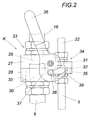
- the plug-in coupling device K is shown in detail in FIG. It has two coupling body 27 and 28 with each other in pairs opposing coupling parts 29, 30 and 31, 32 of plug-in couplings 33, 34, with the aid of the supply and discharge lines 5, 6 of the ground collector to the remaining refrigerant circuit via the lines 16 and 22nd be connected.
- the coupling body 27 has a sliding guide 35 extending in the direction of insertion in the form of guide pins for the coupling body 28, which is provided with corresponding receiving bores for the guide pins.
- the coupling position itself is locked by a provided with an operating handle 36 pivot bolt 37 which is hinged to the coupling body 27 and a roller-shaped locking projection 38 of the coupling body 28 receives in a slotted guide 39, the contraction of the coupling body 27, 28 in the connecting direction and thus ensures a secure clutch engagement. Since the plug-in coupling device K is aligned with respect to its displacement guide 35 perpendicular to the support plate 4 and the coupling parts 29 and 31 for the lines 16 and 22 receiving coupling body 27 is provided on the support plate 4 side facing away from the coupling device K, after unlocking the coupling body 27th and 28 of the supported on the support plate 4 part of the heat pump are lifted from the container 1.
- the shut-off valve 19 connected downstream of the collecting container 14 is closed so that the refrigerant can be sucked out of the loops of the earth collector via the compressor 8 and conveyed into the collecting container 14. Is determined via the pressure switch 25 in the strand 16 of the refrigerant circuit, a predetermined negative pressure, the compressor 8 is turned off and indicated that now the plug-in device 8 can be opened. Since the coupling parts 29, 30 and 31, 32 close automatically during decoupling, an outflow of the refrigerant excluded from these coupling parts after uncoupling of the connectors.
- the intermediate heat exchanger 15 can be short-circuited via the short-circuit line 24.
- the short-circuit line 24 provided in the short-circuit line 24, usually locked shut-off valve 23 to open. With a time delay, the shut-off valve 19 can be closed in the discharge 18 of the intermediate heat exchanger 15 in order to avoid any residual flow of the refrigerant through the intermediate heat exchanger 15.
Landscapes
- Engineering & Computer Science (AREA)
- Physics & Mathematics (AREA)
- Thermal Sciences (AREA)
- Mechanical Engineering (AREA)
- General Engineering & Computer Science (AREA)
- Chemical & Material Sciences (AREA)
- Combustion & Propulsion (AREA)
- Compression-Type Refrigeration Machines With Reversible Cycles (AREA)
- Compressor (AREA)
- Other Air-Conditioning Systems (AREA)
Applications Claiming Priority (1)
| Application Number | Priority Date | Filing Date | Title |
|---|---|---|---|
| AT0033506A AT502829B1 (de) | 2006-02-28 | 2006-02-28 | Wärmepumpe |
Publications (2)
| Publication Number | Publication Date |
|---|---|
| EP1826511A2 true EP1826511A2 (fr) | 2007-08-29 |
| EP1826511A3 EP1826511A3 (fr) | 2008-05-07 |
Family
ID=38117142
Family Applications (1)
| Application Number | Title | Priority Date | Filing Date |
|---|---|---|---|
| EP07450036A Ceased EP1826511A3 (fr) | 2006-02-28 | 2007-02-28 | Pompe à chaleur |
Country Status (2)
| Country | Link |
|---|---|
| EP (1) | EP1826511A3 (fr) |
| AT (1) | AT502829B1 (fr) |
Cited By (2)
| Publication number | Priority date | Publication date | Assignee | Title |
|---|---|---|---|---|
| WO2021228325A1 (fr) | 2020-05-12 | 2021-11-18 | Viessmann Werke Gmbh & Co Kg | Installation de pompe à chaleur |
| WO2024231228A1 (fr) * | 2023-05-05 | 2024-11-14 | Bdr Thermea Group B.V. | Unité de base pour une pompe à chaleur |
Families Citing this family (1)
| Publication number | Priority date | Publication date | Assignee | Title |
|---|---|---|---|---|
| DE102020122713B4 (de) | 2020-08-31 | 2024-10-31 | Andreas Bangheri | Verfahren zum Betreiben einer Wärmepumpe |
Family Cites Families (9)
| Publication number | Priority date | Publication date | Assignee | Title |
|---|---|---|---|---|
| US3424480A (en) * | 1966-03-30 | 1969-01-28 | Richard W Holland | Closure connection means for a heat exchanger |
| DE2946041A1 (de) * | 1979-11-15 | 1981-05-21 | Diehn, Manfred, 2000 Hamburg | Waermepumpe |
| US4516629A (en) * | 1982-04-06 | 1985-05-14 | Thermal Concepts, Inc. | Earth-type heat exchanger for heat pump system |
| FR2716958B1 (fr) * | 1994-03-01 | 1998-07-03 | Solterm | Pompe à chaleur monobloc à capteur enterré. |
| DE19820818C2 (de) * | 1998-05-09 | 2002-12-05 | Viessmann Werke Kg | Wärmepumpe |
| DE10142779A1 (de) * | 2001-08-31 | 2003-03-27 | Viessmann Werke Kg | Kompaktheizgerät |
| JP2003106492A (ja) * | 2001-09-28 | 2003-04-09 | Toyox Co Ltd | 継 手 |
| FR2842288B1 (fr) * | 2002-07-12 | 2005-07-15 | Avenir En | Pompe a chaleur |
| DE10337889B3 (de) * | 2003-08-18 | 2004-12-09 | Webasto Thermosysteme Gmbh | Klimatisierungssystem für ein Kraftfahrzeug und Verfahren zum Betreiben eines Klimatisierungssystems |
-
2006
- 2006-02-28 AT AT0033506A patent/AT502829B1/de not_active IP Right Cessation
-
2007
- 2007-02-28 EP EP07450036A patent/EP1826511A3/fr not_active Ceased
Cited By (3)
| Publication number | Priority date | Publication date | Assignee | Title |
|---|---|---|---|---|
| WO2021228325A1 (fr) | 2020-05-12 | 2021-11-18 | Viessmann Werke Gmbh & Co Kg | Installation de pompe à chaleur |
| DE102020112799A1 (de) | 2020-05-12 | 2021-11-18 | Viessmann Werke Gmbh & Co Kg | Wärmepumpenanlage |
| WO2024231228A1 (fr) * | 2023-05-05 | 2024-11-14 | Bdr Thermea Group B.V. | Unité de base pour une pompe à chaleur |
Also Published As
| Publication number | Publication date |
|---|---|
| AT502829B1 (de) | 2007-06-15 |
| EP1826511A3 (fr) | 2008-05-07 |
| AT502829A4 (de) | 2007-06-15 |
Similar Documents
| Publication | Publication Date | Title |
|---|---|---|
| DE2243733C3 (de) | Narkoseeinrichtung | |
| DE19723232A1 (de) | Wärmetauscher, Verfahren zur Wiederbenutzung und Rückgewinnung des Kühlmittels desselben | |
| DE3202279A1 (de) | Gasuebergabestation | |
| EP3648997A1 (fr) | Installation frigorifique pour véhicule pourvue d'un circuit de réfrigération équipé d'un échangeur thermique et échangeur thermique conçu pour une telle installation frigorifique | |
| EP0099501A2 (fr) | Méthode pour changer la production d'énergie électrique d'une centrale de chauffe sans influencer la livraison de chaleur aux consommateurs de chaleur | |
| EP0951981A2 (fr) | Système de conditionnement thermique multi-voies | |
| DE102007013520B4 (de) | Anordnung zum Führen von Kühlmittel für einen Schaltschrank oder ein Rack Schaltschrank oder Rack damit und Anreihanordnung mit mindestens zwei solchen Schaltschränken oder Racks | |
| EP1826511A2 (fr) | Pompe à chaleur | |
| DE2605994C2 (de) | Warmwasserbereitungsanlage | |
| EP0191309B1 (fr) | Echangeur ou collecteur d'eau sous enduit | |
| DE3037293C2 (fr) | ||
| DE102006021800B3 (de) | Armaturenbausatz zum Be- oder Nachfüllen von Heizungssystemen | |
| DE202009017577U1 (de) | Heiz- und Kühleinrichtungen mit einer Wärmepumpe | |
| DE102012022576A1 (de) | Sicherheitsventilgruppe | |
| DE9404319U1 (de) | Kälteerzeugungsanlage | |
| DE9404321U1 (de) | Kälteerzeugungsanlage | |
| DE2248761C3 (de) | Einloch-Mischbatterie für Spültische mit zusätzlichem Wasseranschluß von Haushaltsmaschinen | |
| DE102023136090A1 (de) | Tiefgezogener Hydraulikanschluss | |
| DE102020129393A1 (de) | Leistungsmodul für eine elektrische Maschine | |
| EP2418441B1 (fr) | Réservoir de glace | |
| DE4304041A1 (de) | Heizungsanlage | |
| AT528385A4 (de) | Wechselvorrichtung für ein Durchführen eines Wechselverfahrens zum Wechseln eines Zellenstapels eines elektrochemischen Zellensystem im laufenden Betrieb des elektrochemischen Zellensystems | |
| DE102009022704B4 (de) | System aus einer von einem Fluid durchströmten Versorgungsleitung, einem Wärmetauscher und einer Anschlussleitung | |
| DE654639C (de) | Dampfsammelleitung | |
| EP3674610A1 (fr) | Dispositif de production de la chaleur |
Legal Events
| Date | Code | Title | Description |
|---|---|---|---|
| PUAI | Public reference made under article 153(3) epc to a published international application that has entered the european phase |
Free format text: ORIGINAL CODE: 0009012 |
|
| AK | Designated contracting states |
Kind code of ref document: A2 Designated state(s): AT BE BG CH CY CZ DE DK EE ES FI FR GB GR HU IE IS IT LI LT LU LV MC NL PL PT RO SE SI SK TR |
|
| AX | Request for extension of the european patent |
Extension state: AL BA HR MK YU |
|
| PUAL | Search report despatched |
Free format text: ORIGINAL CODE: 0009013 |
|
| AK | Designated contracting states |
Kind code of ref document: A3 Designated state(s): AT BE BG CH CY CZ DE DK EE ES FI FR GB GR HU IE IS IT LI LT LU LV MC NL PL PT RO SE SI SK TR |
|
| AX | Request for extension of the european patent |
Extension state: AL BA HR MK RS |
|
| 17P | Request for examination filed |
Effective date: 20081024 |
|
| 17Q | First examination report despatched |
Effective date: 20081201 |
|
| AKX | Designation fees paid |
Designated state(s): AT BE BG CH CY CZ DE DK EE ES FI FR GB GR HU IE IS IT LI LT LU LV MC NL PL PT RO SE SI SK TR |
|
| STAA | Information on the status of an ep patent application or granted ep patent |
Free format text: STATUS: THE APPLICATION HAS BEEN REFUSED |
|
| 18R | Application refused |
Effective date: 20091217 |