EP1826745A1 - Flüssigkristallanzeige und Steuerverfahren dafür - Google Patents
Flüssigkristallanzeige und Steuerverfahren dafür Download PDFInfo
- Publication number
- EP1826745A1 EP1826745A1 EP07002551A EP07002551A EP1826745A1 EP 1826745 A1 EP1826745 A1 EP 1826745A1 EP 07002551 A EP07002551 A EP 07002551A EP 07002551 A EP07002551 A EP 07002551A EP 1826745 A1 EP1826745 A1 EP 1826745A1
- Authority
- EP
- European Patent Office
- Prior art keywords
- area
- display
- frame data
- image frame
- luminance
- Prior art date
- Legal status (The legal status is an assumption and is not a legal conclusion. Google has not performed a legal analysis and makes no representation as to the accuracy of the status listed.)
- Withdrawn
Links
- 238000000034 method Methods 0.000 title claims abstract description 76
- 239000004973 liquid crystal related substance Substances 0.000 title claims abstract description 59
- 230000007613 environmental effect Effects 0.000 claims description 10
- 230000001360 synchronised effect Effects 0.000 claims description 8
- 230000007423 decrease Effects 0.000 claims 2
- 238000010586 diagram Methods 0.000 description 3
- 230000004397 blinking Effects 0.000 description 2
- 230000000694 effects Effects 0.000 description 2
- 238000012986 modification Methods 0.000 description 2
- 230000004048 modification Effects 0.000 description 2
- 230000003287 optical effect Effects 0.000 description 1
Images


Classifications
-
- G—PHYSICS
- G09—EDUCATION; CRYPTOGRAPHY; DISPLAY; ADVERTISING; SEALS
- G09G—ARRANGEMENTS OR CIRCUITS FOR CONTROL OF INDICATING DEVICES USING STATIC MEANS TO PRESENT VARIABLE INFORMATION
- G09G3/00—Control arrangements or circuits, of interest only in connection with visual indicators other than cathode-ray tubes
- G09G3/20—Control arrangements or circuits, of interest only in connection with visual indicators other than cathode-ray tubes for presentation of an assembly of a number of characters, e.g. a page, by composing the assembly by combination of individual elements arranged in a matrix no fixed position being assigned to or needed to be assigned to the individual characters or partial characters
- G09G3/34—Control arrangements or circuits, of interest only in connection with visual indicators other than cathode-ray tubes for presentation of an assembly of a number of characters, e.g. a page, by composing the assembly by combination of individual elements arranged in a matrix no fixed position being assigned to or needed to be assigned to the individual characters or partial characters by control of light from an independent source
- G09G3/3406—Control of illumination source
- G09G3/342—Control of illumination source using several illumination sources separately controlled corresponding to different display panel areas, e.g. along one dimension such as lines
- G09G3/3426—Control of illumination source using several illumination sources separately controlled corresponding to different display panel areas, e.g. along one dimension such as lines the different display panel areas being distributed in two dimensions, e.g. matrix
-
- G—PHYSICS
- G09—EDUCATION; CRYPTOGRAPHY; DISPLAY; ADVERTISING; SEALS
- G09G—ARRANGEMENTS OR CIRCUITS FOR CONTROL OF INDICATING DEVICES USING STATIC MEANS TO PRESENT VARIABLE INFORMATION
- G09G2310/00—Command of the display device
- G09G2310/02—Addressing, scanning or driving the display screen or processing steps related thereto
- G09G2310/024—Scrolling of light from the illumination source over the display in combination with the scanning of the display screen
-
- G—PHYSICS
- G09—EDUCATION; CRYPTOGRAPHY; DISPLAY; ADVERTISING; SEALS
- G09G—ARRANGEMENTS OR CIRCUITS FOR CONTROL OF INDICATING DEVICES USING STATIC MEANS TO PRESENT VARIABLE INFORMATION
- G09G2320/00—Control of display operating conditions
- G09G2320/02—Improving the quality of display appearance
- G09G2320/0247—Flicker reduction other than flicker reduction circuits used for single beam cathode-ray tubes
-
- G—PHYSICS
- G09—EDUCATION; CRYPTOGRAPHY; DISPLAY; ADVERTISING; SEALS
- G09G—ARRANGEMENTS OR CIRCUITS FOR CONTROL OF INDICATING DEVICES USING STATIC MEANS TO PRESENT VARIABLE INFORMATION
- G09G2320/00—Control of display operating conditions
- G09G2320/02—Improving the quality of display appearance
- G09G2320/0261—Improving the quality of display appearance in the context of movement of objects on the screen or movement of the observer relative to the screen
-
- G—PHYSICS
- G09—EDUCATION; CRYPTOGRAPHY; DISPLAY; ADVERTISING; SEALS
- G09G—ARRANGEMENTS OR CIRCUITS FOR CONTROL OF INDICATING DEVICES USING STATIC MEANS TO PRESENT VARIABLE INFORMATION
- G09G2320/00—Control of display operating conditions
- G09G2320/10—Special adaptations of display systems for operation with variable images
- G09G2320/103—Detection of image changes, e.g. determination of an index representative of the image change
Definitions
- the invention relates to a liquid crystal display device and a control method thereof, and, in particular, to a liquid crystal display device and a control method thereof, which can perform a flash control of the display area(s) displaying the animation.
- the liquid crystal display devices are widely used in many application fields.
- the liquid crystal display device can be used as a monitor of a computer, a touch control panel for the human-machine interface (HMI), or a television for cooperating with the video system.
- HMI human-machine interface
- the view angle problem the contrast problem
- the color saturation problem the response time problem.
- the goal for solving the response time problem is to make the liquid crystal display device having the animation display effect as a CRT (cathode-ray tube) displayer.
- the reason why the conventional liquid crystal display device can not achieve the desired animation display effect is that, excepting the limitation of response time, the conventional liquid crystal display device renders the hold-type display method, which is different from the impulse-type display method used in the CRT displayer.
- the human eyes may not have the blurring phenomenon when tracking the motion object on the screen.
- the human eyes may have the blurring phenomenon when tracking the motion object on the screen.
- the manufacturer discloses a blinking technology for solving the blurring phenomenon.
- the blinking technology is to repeatedly turn on and turn off the light-emitting units of the backlighting, so that the backlighting of the liquid crystal display device can imitate the impulse-type display method so as to eliminate the blurring phenomenon.
- the light-emitting units are turned on/off repeatedly, the luminance of the display screen may change by a wide margin, which leads to the flicker phenomenon in vision.
- the manufacturer also discloses a sequential flashing technology for solving the blurring phenomenon.
- the sequential flashing technology is to light on and turn off the light-emitting units during a frame time in sequence, so that the light-emitting units can flash in turn to imitate the impulse-type display method for improving the blurring phenomenon of the motion image.
- the motionless image may have the flicker phenomenon in vision.
- the residual part of the motionless image may have flicker phenomenon in vision.
- the invention is to provide a liquid crystal display device and a control method thereof, which can improve the blurring phenomenon and prevent the flicker phenomenon.
- a control method of the invention is used for inputting a plurality of image frame data into a liquid crystal display device in order.
- the liquid crystal display device includes a plurality of light-emitting diodes as a backlighting and a display screen, and has a preset display mode reference.
- the display screen is divided into a plurality of display areas, which are arranged in a two-dimensional array. Each of the display areas corresponds to one of the light-emitting diodes.
- Each of the image frame data includes a plurality of area image frame data corresponding to the display areas, respectively.
- the method includes an area image frame data comparison/judgment procedure and an area light-emitting diode control procedure.
- the area image frame data comparison/judgment procedure compares at least two of the area image frame data displayed in one of the display areas at different timings so as to generate an area image display parameter, and then determines whether the display area should perform an area synchronization flash control mode or not according to the area image display parameter and the display mode reference. If the area image frame data comparison/judgment procedure determines that the display area should perform the area synchronization flash control mode, the area light-emitting diode control procedure controls the light-emitting diode corresponding to the display area to perform the area synchronization flash control mode.
- a liquid crystal display device of the invention includes a plurality of light-emitting diodes as a backlighting and a display screen, and has a preset display mode reference.
- the display screen is divided into a plurality of display areas, which are arranged in a two-dimensional array. Each of the display areas corresponds to one of the light-emitting diodes.
- Each of the image frame data includes a plurality of area image frame data respectively corresponding to the display areas.
- the liquid crystal display device includes an area image frame data comparison/judgment module and an area light-emitting diode control module.
- the area image frame data comparison/judgment module compares at least two of the area image frame data displayed in one of the display areas at different timings so as to generate an area image display parameter, and then generates an area luminance control signal according to the area image display parameter and the display mode reference.
- the area light-emitting diode control module which is electrically connected with the area image frame data comparison/judgment module, controls at least the light-emitting diode corresponding to the display area to perform a luminance control mode according to the area luminance control signal.
- the liquid crystal display device and the control method thereof of the invention are to obtain an area image display parameter by comparing/calculating the pixel data of the area image frame data, and to determine whether the area image frame data represents an animation display mode or not after comparing the area image display parameter and the display mode reference. Then, the invention can decide whether to perform an area synchronization flash control mode on the display area. Accordingly, the invention can improve the blurring phenomenon and prevent the flicker phenomenon of the liquid crystal display device.
- FIG. 1 is a schematic diagram showing image frame data, which are inputted into a liquid crystal display device according to a preferred embodiment of the invention
- FIG. 2 is a schematic diagram showing image frame data, which are inputted into another liquid crystal display device according to the embodiment of the invention.
- FIG. 3 is a flow chart showing the procedures of a control method of a liquid crystal display device according to a preferred embodiment of the invention.
- FIG. 4 is a flow chart showing the steps of the control method of a liquid crystal display device according to the embodiment of the invention.
- FIG. 5 is a flow chart showing the steps of another control method of a liquid crystal display device according to the embodiment of the invention.
- FIG. 6 is a schematic diagram showing a liquid crystal display device according to a preferred embodiment of the invention.
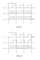
- FIG. 7 is a timing chart showing the control of the light-emitting units of the liquid crystal display device according to the embodiment of the invention, wherein L 2 and L 3 represent the timings for continuously lighting up the light-emitting units, and T F represents an image frame data time;
- FIG. 8 is a timing chart showing the another control of the light-emitting units of the liquid crystal display device according to the embodiment of the invention, wherein L 3 represents the timing for continuously lighting up the light-emitting unit, and T F represents an image frame data time;
- FIG. 9 is a timing chart showing yet another control of the light-emitting units of the liquid crystal display device according to the embodiment of the invention, wherein L 2 and L 3 represent the timings for performing the flash control mode having a frequency different from the writing frequency of the image frame data, and T F represents an image frame data time; and
- FIG. 10 is a timing chart showing still another control of the light-emitting units of the liquid crystal display device according to the embodiment of the invention, wherein L 3 represents the timing for performing the flash control mode having a frequency different from the writing frequency of the image frame data, and T F represents an image frame data time.
- a liquid crystal display device 1 usually includes a display screen 11 and light-emitting units 2, such as the cold cathode fluorescent lamps (CCFL), as the backlighting.
- the light-emitting units may be other light sources.
- another liquid crystal display device 1' includes a display screen 11' and light-emitting units 2', such as the light-emitting diodes (LED), as the backlighting.
- LED light-emitting diodes
- the light-emitting units are, for example, the cold cathode fluorescent lamps for describing a control method of a liquid crystal display device according to a preferred embodiment of the invention.
- the liquid crystal display device 1 has a preset display mode reference.
- the display mode reference is an animation display mode reference for determining whether a display screen 11 displays the animation image.
- the display screen 11 is divided into a plurality of display areas A l to A n , wherein n is positive integer.
- Each of the display areas A l to A n corresponds to one of the light-emitting units 2 (L l to L n , wherein n is positive integer).
- Each of the image frame data includes a plurality of area image frame data respectively corresponding to the display areas A l to A n .
- each light-emitting unit 2 includes one cold cathode fluorescent lamp only, but it may include several cold cathode fluorescent lamps in practice.
- control method of the liquid crystal display device includes an area image frame data comparison/judgment procedure P1 and an area light-emitting unit control procedure P2.
- the area image frame data comparison/judgment procedure P1 is applied to any one of the display areas A l to A n .
- the area image frame data comparison/judgment procedure P1 is for comparing at least two area image frame data I 1l and I 2l , which are displayed in the display area A 1 at different timings, so as to generate an area image display parameter. Then, the procedure P1 determines whether the display area A l should perform an area synchronization flash control mode or not according to the area image display parameter and the display mode reference.
- the two area image frame data I n and I 2l may respectively belong to two sequentially inputted image frame data or two non-sequentially inputted image frame data.
- the first image frame data I 1 and the second image frame data I 2 may be sequentially inputted image frame data or non-sequentially inputted image frame data.
- the first image frame data I 1 and the second image frame data I 2 respectively include a plurality of area image frame data I 1l to I 1n and area image frame data I 2l to I 2n , wherein n is positive integer.
- Each of the area image frame data I 1l to I 1n and I 2l to I 2n contains a plurality of pixel data for displaying its corresponding display area.
- Each of the pixel data is composed of sub-pixel values, such as the RGB sub-pixel values or YUV sub-pixel values, and includes 24 bits.
- Each color sub-pixel value (Red, Green, or Blue) is represented by 8 bits, which means 0 to 255.
- the procedure P1 can calculate the area image display reference, which represents the motion composition, according to each color sub-pixel value of each area image frame data I 1l to I 1n and each color sub-pixel value of each corresponding area image frame data I 2l to I 2n . Then, the procedure P1 determines whether the display area should perform an area synchronization flash control mode or not according to each area image display parameter and the display mode reference. In the present embodiment, when the area image display parameter is larger than the display mode reference, the procedure P1 determines that the display area should perform the area synchronization flash control mode. In this case, the display mode of the display area is an animation display mode.
- the calculating method for obtaining the above-mentioned result is not limited to the previously described method.
- the optical flow technique may also be used to calculate the motion composition of the display screen.
- the area light-emitting unit control procedure P2 controls the light-emitting unit corresponding to the display area to perform the area synchronization flash control mode if the area image frame data comparison/judgment procedure P1 determines that the display area should perform the area synchronization flash control mode.
- the area synchronization flash control mode is to control the luminance intensities of the light-emitting unit corresponding to the display area to present a periodical luminance waveform.
- the luminance waveform and a timing of the area image frame data written into the display area are synchronized with a phase difference.
- the phase difference is ranged from 0 to 360 degrees.
- FIG. 7 is a timing chart showing the driven light-emitting units.
- the display area A 1 when the display area A 1 is determined as an animation display mode, it performs an area synchronization flash control mode for executing an area flash control on the light-emitting unit L 1 corresponding to the display area A 1 . Accordingly, the backlighting of the display area presents a periodical luminance waveform.
- the area light-emitting unit control procedure P2 performs the area synchronization flash control mode by controlling luminance intensities of the light-emitting unit L 1 corresponding to the display area A 1 and another light-emitting unit L 2 corresponding to another display area A 2 adjacent to the display area A 1 to present a periodical luminance waveform.
- the periodical luminance waveform and a timing of the area image frame data written into the display areas are synchronized with a phase difference.
- the area light-emitting unit control procedure P2 controls the light-emitting unit corresponding to the display area to perform a general luminance control mode.
- the general luminance control mode is to continuously light on the light-emitting unit or to control the light-emitting unit with a flash control mode having a frequency different from the writing frequency of the image frame data.
- the reference numbers L 2 and L 3 of FIG. 7 and L 3 of FIG. 8 represent the timing of the continuously lighted light-emitting unit.
- the reference numbers L 2 and L 3 of FIG. 9 and L 3 of FIG. 10 represent the timing of the light-emitting unit, which is controlled with the flash control mode having a frequency different from the writing frequency of the image frame data.
- the light-emitting units are the light-emitting diodes.
- the liquid crystal display device 1' has a preset display mode reference.
- the display mode reference is an animation display mode reference for determining whether a display screen 11 displays the animation image.
- the display screen 11' is divided into a plurality of display areas A' l to A' m arranged in a two-dimensional array, wherein m is positive integer.
- Each of the display areas A' l to A' m corresponds to one of the light-emitting units 2'.
- Each of the image frame data includes a plurality of area image frame data respectively corresponding to the display areas A' l to A' m .
- each light-emitting unit 2' may include one light-emitting diode only, or several light-emitting diodes.
- the area image frame data comparison/judgment procedure P1 is applied to any one of the display areas A' l to A' m .
- the area image frame data comparison/judgment procedure P1 is for comparing at least two area image frame data I' 1l and I' 2l , which are displayed in the display area A' l at different timings, so as to generate an area image display parameter. Then, the procedure P1 determines whether the display area A' l should perform an area synchronization flash control mode or not according to the area image display parameter and the display mode reference.
- the two area image frame data I' 1l and I' 2l may respectively belong to two sequentially inputted image frame data or two non-sequentially inputted image frame data.
- the first image frame data I 1 and the second image frame data I 2 may be sequentially inputted image frame data or non-sequentially inputted image frame data.
- the first image frame data I 1 and the second image frame data I 2 respectively include a plurality of area image frame data I' 1l to I' 1m and area image frame data I' 2l to I' 2m , wherein m is positive integer.
- Each of the area image frame data I' 1l to I' 1m and I' 2l to I' 2m contains a plurality of pixel data for displaying its corresponding display area.
- the procedure P1 can calculate the area image display reference, which represents the motion composition, according to each color sub-pixel value of each area image frame data I' 1l to I' 1m and each color sub-pixel value of each corresponding area image frame data I' 2l to I' 2m . Then, the procedure P1 determines whether the display area should perform an area synchronization flash control mode or not according to each area image display parameter and the display mode reference.
- the area synchronization flash control mode is the same as that described herein above, so the detailed descriptions are omitted for concise purpose.
- the invention allows the user to manually adjust the preset display mode reference, or allows the liquid crystal display device to automatically adjust the preset display mode reference.
- the display mode reference can be set to decide what kind of the animation display mode should be perform the area synchronization flash control mode for eliminating the blurring phenomenon.
- the display mode reference of the invention can be modulated depending on a luminance.
- the luminance can be a luminance of the liquid crystal display device or an environmental luminance.
- the display mode reference should be modulated higher when the luminance of the liquid crystal display device is brighter, and the display mode reference should be modulated lower when the environmental luminance is brighter.
- the liquid crystal display device according to a preferred embodiment of the invention will be described hereinafter with reference to FIGS. 6 to 8.
- the control method of the light-emitting units of the liquid crystal display device is the same as that described herein above, the detailed descriptions are omitted for concise purpose
- a liquid crystal display device includes an area image frame data comparison/judgment module 3 and an area light-emitting unit control module 4.
- the liquid crystal display device 1 has a display screen 11 for displaying a plurality of image frame data in order and a preset display mode reference.
- the display screen 11 is divided into a plurality of display areas A l to A n , wherein n is positive integer.
- Each of the display areas A l to A n corresponds to one of the light-emitting units 2.
- Each of the image frame data includes a plurality of area image frame data respectively corresponding to the display areas A l to A n .
- the area image frame data comparison/judgment module 3 is applied to any one of the display areas A l to A n .
- the area image frame data comparison/judgment module 3 compares at least two of the area image frame data displayed in one of the display areas at different timings so as to generate an area image display parameter, and then generating an area luminance control signal according to the area image display parameter and the display mode reference.
- the area light-emitting unit control module 4 which is electrically connected with the area image frame data comparison/judgment module 3, controls at least the light-emitting unit corresponding to the display area to perform a luminance control mode according to the area luminance control signal.
- the display mode reference is an animation display mode reference.
- the area image display parameter is larger than the display mode reference
- the area image frame data comparison/judgment module 3 determines that the display mode of the display area is an animation display mode.
- the luminance control mode is an area synchronization flash control mode, which controls the luminance intensity of the light-emitting unit corresponding to the display area to present a periodical luminance waveform (as shown in FIG. 7).
- the periodical luminance waveform and a timing of the area image frame data written into the display area are synchronized with a phase difference.
- the luminance control mode may control the luminance intensities of the light-emitting unit corresponding to the display area and another light-emitting unit corresponding to another display area adjacent to the display area to present a periodical luminance waveform (as shown in FIG. 8).
- the periodical luminance waveform and a timing of the area image frame data written into the display areas are synchronized with a phase difference.
- the above descriptions of the embodiment illustrate the case of using the cold cathode fluorescent lamps as the light-emitting units.
- the control method is the same as that described herein above.
- the invention allows the user to manually adjust the preset display mode reference, or allows the liquid crystal display device to automatically adjust the preset display mode reference.
- the display mode reference can be set to decide what kind of the animation display mode should be perform the area synchronization flash control mode for eliminating the blurring phenomenon.
- the display mode reference of the invention can be modulated depending on a luminance.
- the luminance can be a luminance of the liquid crystal display device or an environmental luminance.
- the display mode reference should be modulated higher when the luminance of the liquid crystal display device is brighter, and the display mode reference should be modulated lower when the environmental luminance is brighter.
- the liquid crystal display device and the control method thereof of the invention break the conventional thought of always performing the flash control or never performing the flash control in one display device.
- the liquid crystal display device and the control method thereof of the invention are to compare the pixel data of the area image frame data so as to determine whether the area image frame data represents an animation display mode or not and thus decide whether to perform an area synchronization flash control mode on the display area.
- the display areas displaying the motionless image will not perform the area synchronization flash control mode, so that the flicker phenomenon can be prevented.
- the display areas displaying the motion image will perform the area synchronization flash control mode, so that the blurring phenomenon can be improved.
- the invention further considers the luminance factor, so that the invention can efficiently improve the blurring phenomenon and prevent the flicker phenomenon of the liquid crystal display device.
Landscapes
- Engineering & Computer Science (AREA)
- Physics & Mathematics (AREA)
- Computer Hardware Design (AREA)
- General Physics & Mathematics (AREA)
- Theoretical Computer Science (AREA)
- Liquid Crystal Display Device Control (AREA)
- Control Of Indicators Other Than Cathode Ray Tubes (AREA)
Applications Claiming Priority (1)
| Application Number | Priority Date | Filing Date | Title |
|---|---|---|---|
| CNB2006100580642A CN100511397C (zh) | 2006-02-28 | 2006-02-28 | 液晶显示装置及其控制方法 |
Publications (1)
| Publication Number | Publication Date |
|---|---|
| EP1826745A1 true EP1826745A1 (de) | 2007-08-29 |
Family
ID=37897330
Family Applications (1)
| Application Number | Title | Priority Date | Filing Date |
|---|---|---|---|
| EP07002551A Withdrawn EP1826745A1 (de) | 2006-02-28 | 2007-02-06 | Flüssigkristallanzeige und Steuerverfahren dafür |
Country Status (2)
| Country | Link |
|---|---|
| EP (1) | EP1826745A1 (de) |
| CN (1) | CN100511397C (de) |
Cited By (1)
| Publication number | Priority date | Publication date | Assignee | Title |
|---|---|---|---|---|
| EP2279506A4 (de) * | 2008-05-29 | 2011-07-13 | Sharp Kk | Verfahren und system zur reduzierung von flimmern und unschärfe |
Families Citing this family (1)
| Publication number | Priority date | Publication date | Assignee | Title |
|---|---|---|---|---|
| CN111754945B (zh) * | 2019-03-29 | 2021-12-28 | 合肥鑫晟光电科技有限公司 | 用于控制显示装置的驱动的方法、装置和显示装置 |
Citations (4)
| Publication number | Priority date | Publication date | Assignee | Title |
|---|---|---|---|---|
| EP1091341A2 (de) * | 1999-10-04 | 2001-04-11 | Hitachi, Ltd. | Flüssigkristallvorrichtung und Steuerverfahren dafür |
| EP1197944A2 (de) * | 2000-10-13 | 2002-04-17 | Nec Corporation | Flüssigkristallanzeige und Computer |
| US20020057238A1 (en) | 2000-09-08 | 2002-05-16 | Hiroyuki Nitta | Liquid crystal display apparatus |
| EP1551002A2 (de) * | 2004-01-05 | 2005-07-06 | Fujitsu Limited | Steuerung der Synchronisation eines Rückbeleuchtungsgerätes für ein Flüssigkristallanzeigegerät |
-
2006
- 2006-02-28 CN CNB2006100580642A patent/CN100511397C/zh not_active Expired - Lifetime
-
2007
- 2007-02-06 EP EP07002551A patent/EP1826745A1/de not_active Withdrawn
Patent Citations (4)
| Publication number | Priority date | Publication date | Assignee | Title |
|---|---|---|---|---|
| EP1091341A2 (de) * | 1999-10-04 | 2001-04-11 | Hitachi, Ltd. | Flüssigkristallvorrichtung und Steuerverfahren dafür |
| US20020057238A1 (en) | 2000-09-08 | 2002-05-16 | Hiroyuki Nitta | Liquid crystal display apparatus |
| EP1197944A2 (de) * | 2000-10-13 | 2002-04-17 | Nec Corporation | Flüssigkristallanzeige und Computer |
| EP1551002A2 (de) * | 2004-01-05 | 2005-07-06 | Fujitsu Limited | Steuerung der Synchronisation eines Rückbeleuchtungsgerätes für ein Flüssigkristallanzeigegerät |
Cited By (2)
| Publication number | Priority date | Publication date | Assignee | Title |
|---|---|---|---|---|
| EP2279506A4 (de) * | 2008-05-29 | 2011-07-13 | Sharp Kk | Verfahren und system zur reduzierung von flimmern und unschärfe |
| US8068087B2 (en) | 2008-05-29 | 2011-11-29 | Sharp Laboratories Of America, Inc. | Methods and systems for reduced flickering and blur |
Also Published As
| Publication number | Publication date |
|---|---|
| CN100511397C (zh) | 2009-07-08 |
| CN101030358A (zh) | 2007-09-05 |
Similar Documents
| Publication | Publication Date | Title |
|---|---|---|
| US6970148B2 (en) | Image display method | |
| US20110063330A1 (en) | Method and apparatus for reducing erroneous color effects in a field sequential liquid crystal display | |
| US8031162B2 (en) | Display device and method, recording medium, and program | |
| JP2009134237A (ja) | 表示装置 | |
| WO2005081217A1 (ja) | 映像表示装置 | |
| JP2011512548A (ja) | 電子ディスプレイのバックライト制御のためのシステムおよび方法 | |
| WO2009096068A1 (ja) | 画像表示装置および画像表示方法 | |
| US20130088506A1 (en) | Display apparatus and driving method thereof | |
| JP5132763B2 (ja) | 液晶画像表示装置 | |
| CN103137090A (zh) | 显示图像的设备和方法 | |
| US9653026B2 (en) | Backlight controlling apparatus, backlight controlling method and program | |
| US11183128B2 (en) | Liquid crystal display and display calibration method thereof | |
| US20070182696A1 (en) | Liquid crystal display device and controlling method thereof | |
| KR100700016B1 (ko) | 액정 표시 장치 및 그 구동방법 | |
| EP1826745A1 (de) | Flüssigkristallanzeige und Steuerverfahren dafür | |
| TWI394127B (zh) | Method of generating control signal for compression response time | |
| CN104299576A (zh) | 一种显示驱动方法、装置及显示器 | |
| US11900891B2 (en) | Backlight system, display apparatus, and light emission control method | |
| KR101126499B1 (ko) | 액정표시장치 및 구동방법 | |
| US7623104B2 (en) | Display and display control method | |
| US20080191999A1 (en) | Method for displaying a moving image on a display | |
| KR101343495B1 (ko) | 액정표시장치의 백라이트 제어 회로 | |
| TWI541789B (zh) | 壓縮反應時間之畫面控制訊號產生方法 | |
| KR102760139B1 (ko) | 픽셀 데이터 변조를 통하여 프레임 특성에 따라 가변적으로 절전을 수행하는 모니터 제어 장치 및 방법 | |
| TWI326864B (de) |
Legal Events
| Date | Code | Title | Description |
|---|---|---|---|
| PUAI | Public reference made under article 153(3) epc to a published international application that has entered the european phase |
Free format text: ORIGINAL CODE: 0009012 |
|
| AK | Designated contracting states |
Kind code of ref document: A1 Designated state(s): AT BE BG CH CY CZ DE DK EE ES FI FR GB GR HU IE IS IT LI LT LU LV MC NL PL PT RO SE SI SK TR |
|
| AX | Request for extension of the european patent |
Extension state: AL BA HR MK YU |
|
| 17P | Request for examination filed |
Effective date: 20080225 |
|
| 17Q | First examination report despatched |
Effective date: 20080410 |
|
| AKX | Designation fees paid |
Designated state(s): DE FR |
|
| STAA | Information on the status of an ep patent application or granted ep patent |
Free format text: STATUS: THE APPLICATION IS DEEMED TO BE WITHDRAWN |
|
| 18D | Application deemed to be withdrawn |
Effective date: 20120413 |