EP1828516B2 - Tuerantrieb - Google Patents
Tuerantrieb Download PDFInfo
- Publication number
- EP1828516B2 EP1828516B2 EP05806642.4A EP05806642A EP1828516B2 EP 1828516 B2 EP1828516 B2 EP 1828516B2 EP 05806642 A EP05806642 A EP 05806642A EP 1828516 B2 EP1828516 B2 EP 1828516B2
- Authority
- EP
- European Patent Office
- Prior art keywords
- housing
- coupling
- door operator
- hand
- housings
- Prior art date
- Legal status (The legal status is an assumption and is not a legal conclusion. Google has not performed a legal analysis and makes no representation as to the accuracy of the status listed.)
- Expired - Lifetime
Links
Images


Classifications
-
- E—FIXED CONSTRUCTIONS
- E05—LOCKS; KEYS; WINDOW OR DOOR FITTINGS; SAFES
- E05F—DEVICES FOR MOVING WINGS INTO OPEN OR CLOSED POSITION; CHECKS FOR WINGS; WING FITTINGS NOT OTHERWISE PROVIDED FOR, CONCERNED WITH THE FUNCTIONING OF THE WING
- E05F3/00—Closers or openers with braking devices, e.g. checks; Construction of pneumatic or liquid braking devices
- E05F3/22—Additional arrangements for closers, e.g. for holding the wing in opened or other position
-
- E—FIXED CONSTRUCTIONS
- E05—LOCKS; KEYS; WINDOW OR DOOR FITTINGS; SAFES
- E05F—DEVICES FOR MOVING WINGS INTO OPEN OR CLOSED POSITION; CHECKS FOR WINGS; WING FITTINGS NOT OTHERWISE PROVIDED FOR, CONCERNED WITH THE FUNCTIONING OF THE WING
- E05F15/00—Power-operated mechanisms for wings
- E05F15/60—Power-operated mechanisms for wings using electrical actuators
- E05F15/603—Power-operated mechanisms for wings using electrical actuators using rotary electromotors
- E05F15/611—Power-operated mechanisms for wings using electrical actuators using rotary electromotors for swinging wings
-
- E—FIXED CONSTRUCTIONS
- E05—LOCKS; KEYS; WINDOW OR DOOR FITTINGS; SAFES
- E05F—DEVICES FOR MOVING WINGS INTO OPEN OR CLOSED POSITION; CHECKS FOR WINGS; WING FITTINGS NOT OTHERWISE PROVIDED FOR, CONCERNED WITH THE FUNCTIONING OF THE WING
- E05F3/00—Closers or openers with braking devices, e.g. checks; Construction of pneumatic or liquid braking devices
-
- E—FIXED CONSTRUCTIONS
- E05—LOCKS; KEYS; WINDOW OR DOOR FITTINGS; SAFES
- E05F—DEVICES FOR MOVING WINGS INTO OPEN OR CLOSED POSITION; CHECKS FOR WINGS; WING FITTINGS NOT OTHERWISE PROVIDED FOR, CONCERNED WITH THE FUNCTIONING OF THE WING
- E05F3/00—Closers or openers with braking devices, e.g. checks; Construction of pneumatic or liquid braking devices
- E05F3/04—Closers or openers with braking devices, e.g. checks; Construction of pneumatic or liquid braking devices with liquid piston brakes
- E05F3/10—Closers or openers with braking devices, e.g. checks; Construction of pneumatic or liquid braking devices with liquid piston brakes with a spring, other than a torsion spring, and a piston, the axes of which are the same or lie in the same direction
-
- E—FIXED CONSTRUCTIONS
- E05—LOCKS; KEYS; WINDOW OR DOOR FITTINGS; SAFES
- E05F—DEVICES FOR MOVING WINGS INTO OPEN OR CLOSED POSITION; CHECKS FOR WINGS; WING FITTINGS NOT OTHERWISE PROVIDED FOR, CONCERNED WITH THE FUNCTIONING OF THE WING
- E05F3/00—Closers or openers with braking devices, e.g. checks; Construction of pneumatic or liquid braking devices
- E05F3/22—Additional arrangements for closers, e.g. for holding the wing in opened or other position
- E05F3/224—Additional arrangements for closers, e.g. for holding the wing in opened or other position for assisting in opening the wing
-
- E—FIXED CONSTRUCTIONS
- E05—LOCKS; KEYS; WINDOW OR DOOR FITTINGS; SAFES
- E05Y—INDEXING SCHEME ASSOCIATED WITH SUBCLASSES E05D AND E05F, RELATING TO CONSTRUCTION ELEMENTS, ELECTRIC CONTROL, POWER SUPPLY, POWER SIGNAL OR TRANSMISSION, USER INTERFACES, MOUNTING OR COUPLING, DETAILS, ACCESSORIES, AUXILIARY OPERATIONS NOT OTHERWISE PROVIDED FOR, APPLICATION THEREOF
- E05Y2201/00—Constructional elements; Accessories therefor
- E05Y2201/40—Motors; Magnets; Springs; Weights; Accessories therefor
- E05Y2201/404—Function thereof
- E05Y2201/41—Function thereof for closing
-
- E—FIXED CONSTRUCTIONS
- E05—LOCKS; KEYS; WINDOW OR DOOR FITTINGS; SAFES
- E05Y—INDEXING SCHEME ASSOCIATED WITH SUBCLASSES E05D AND E05F, RELATING TO CONSTRUCTION ELEMENTS, ELECTRIC CONTROL, POWER SUPPLY, POWER SIGNAL OR TRANSMISSION, USER INTERFACES, MOUNTING OR COUPLING, DETAILS, ACCESSORIES, AUXILIARY OPERATIONS NOT OTHERWISE PROVIDED FOR, APPLICATION THEREOF
- E05Y2201/00—Constructional elements; Accessories therefor
- E05Y2201/40—Motors; Magnets; Springs; Weights; Accessories therefor
- E05Y2201/404—Function thereof
- E05Y2201/422—Function thereof for opening
-
- E—FIXED CONSTRUCTIONS
- E05—LOCKS; KEYS; WINDOW OR DOOR FITTINGS; SAFES
- E05Y—INDEXING SCHEME ASSOCIATED WITH SUBCLASSES E05D AND E05F, RELATING TO CONSTRUCTION ELEMENTS, ELECTRIC CONTROL, POWER SUPPLY, POWER SIGNAL OR TRANSMISSION, USER INTERFACES, MOUNTING OR COUPLING, DETAILS, ACCESSORIES, AUXILIARY OPERATIONS NOT OTHERWISE PROVIDED FOR, APPLICATION THEREOF
- E05Y2201/00—Constructional elements; Accessories therefor
- E05Y2201/40—Motors; Magnets; Springs; Weights; Accessories therefor
- E05Y2201/43—Motors
- E05Y2201/434—Electromotors; Details thereof
-
- E—FIXED CONSTRUCTIONS
- E05—LOCKS; KEYS; WINDOW OR DOOR FITTINGS; SAFES
- E05Y—INDEXING SCHEME ASSOCIATED WITH SUBCLASSES E05D AND E05F, RELATING TO CONSTRUCTION ELEMENTS, ELECTRIC CONTROL, POWER SUPPLY, POWER SIGNAL OR TRANSMISSION, USER INTERFACES, MOUNTING OR COUPLING, DETAILS, ACCESSORIES, AUXILIARY OPERATIONS NOT OTHERWISE PROVIDED FOR, APPLICATION THEREOF
- E05Y2201/00—Constructional elements; Accessories therefor
- E05Y2201/60—Suspension or transmission members; Accessories therefor
- E05Y2201/622—Suspension or transmission members elements
- E05Y2201/71—Toothed gearing
- E05Y2201/726—Ring gears; Internal gears
-
- E—FIXED CONSTRUCTIONS
- E05—LOCKS; KEYS; WINDOW OR DOOR FITTINGS; SAFES
- E05Y—INDEXING SCHEME ASSOCIATED WITH SUBCLASSES E05D AND E05F, RELATING TO CONSTRUCTION ELEMENTS, ELECTRIC CONTROL, POWER SUPPLY, POWER SIGNAL OR TRANSMISSION, USER INTERFACES, MOUNTING OR COUPLING, DETAILS, ACCESSORIES, AUXILIARY OPERATIONS NOT OTHERWISE PROVIDED FOR, APPLICATION THEREOF
- E05Y2800/00—Details, accessories and auxiliary operations not otherwise provided for
- E05Y2800/20—Combinations of elements
- E05Y2800/205—Combinations of elements forming a unit
-
- E—FIXED CONSTRUCTIONS
- E05—LOCKS; KEYS; WINDOW OR DOOR FITTINGS; SAFES
- E05Y—INDEXING SCHEME ASSOCIATED WITH SUBCLASSES E05D AND E05F, RELATING TO CONSTRUCTION ELEMENTS, ELECTRIC CONTROL, POWER SUPPLY, POWER SIGNAL OR TRANSMISSION, USER INTERFACES, MOUNTING OR COUPLING, DETAILS, ACCESSORIES, AUXILIARY OPERATIONS NOT OTHERWISE PROVIDED FOR, APPLICATION THEREOF
- E05Y2900/00—Application of doors, windows, wings or fittings thereof
- E05Y2900/10—Application of doors, windows, wings or fittings thereof for buildings or parts thereof
- E05Y2900/13—Type of wing
- E05Y2900/132—Doors
Definitions
- the invention relates to a door drive, which consists of several components, such as mechanical, hydraulic and electric drive units and / or one or more housings, wherein the components are interconnected.
- a swing door drive with an electromechanical drive unit is from the DE 197 56 496 C2 known.
- This revolving door drive has an open construction without a closed housing, wherein the individual components are attached in succession to a cover plate or to a cover, which in turn can be embedded in the door leaf.
- the gearbox and the drive motor are flanged to the cover plates via a bearing bracket. With larger required torques, the gearbox and motor in the outer dimensions are significantly larger than in the FIG. 1 of the DE 197 56 496 C1 is shown.
- the closer springs are screwed with a spring housing to the door closer, wherein the spring housing on the connection side has an internal or external thread which is screwed to a complementary thread on the door closer housing.
- the longitudinal axis of the components as a rotation axis for screwing in the thread, it can not be exactly predetermined in which position the spring housing comes to rest on the door closer.
- no exact position assignment in particular the angular arrangement of the housing is possible.
- components are housing or housing parts understood that can accommodate the pump, the motor or the hydraulic block or be connected to them.
- housings can be connected to each other, which receive the pump, the motor or the hydraulic block. But it can also be attached to a housing pump, motor or hydraulic block, which in turn receives further drive units and drive elements.
- a hydraulic block is essentially referred to the structural summary of valves, lines and / or other hydraulic components.
- components are also understood to mean the basic components of a door closer or door drive, which are e.g. may consist of the cam technology with cam disc and pressure rollers or the piston technology with internally toothed piston and pinion.
- These basic components are installed in a separate housing and combined by means of the coupling with the drive components depending on the application. Since both the cam technology and the piston technology have advantages and disadvantages depending on the application, the appropriate technology can be combined with the help of a uniform assembly, in which the drive motor, hydraulic pump, spring chamber and spring force adjustment are integrated.
- the coupling creates the prerequisite to connect the various components together that work together trouble-free only for an exact location assignment.
- the clutch can Have a cap nut and are screwed onto the components from the outside, or - which is in terms of space for installation in the door of advantage - be in one - or both - components built-in clutch.
- the right and left hand thread of the components is an internal thread, and the complementary thread of the coupling external thread. The coupling is thus screwed into the components.
- the following embodiment relates to the use of the coupling in at least one housing, which is connected to a second housing part.
- the coupling inside have a bore and are penetrated by a piston rod, a spring plunger or a spindle, so that different components with different functions can be connected to each other in a modular manner, and the functions interlock.
- the coupling is sealed to the piston rod and the housing with seals so that a separate pressure chamber can be formed in each housing.
- the coupling may have pin holes on one end, into which the pins of a tool engage.
- a housing can be completely pre-assembled and the coupling is attached to the second housing.
- the tool penetrates the second housing and engages with its pins in the pin holes of the coupling, so that by turning the tool, the coupling is rotated and move the housing axially on the threads on each other.
- the housings are braced until the end faces are firmly together.
- hydraulic door drive hydraulic channels are incorporated into the housing parallel to a longitudinal axis of the housing, which are connected to each other in alignment with the superposed end faces of the housing connected to the coupling.
- the emerging at the ends of the housing channels and lines can be sealed with little effort to the outside to the gap between the housings and connected to each other.
- a not to be underestimated advantage results in the production of these channels and lines, as very deep holes are always very expensive to manufacture and inaccurate in tolerances.
- the bores along the longitudinal axis for the hydraulic channels may have a smaller depth, since the exact axial position assignment and angle assignment a connection of the channels on the faces of the components is possible without problems.
- a further improvement results when in the contiguous open hydraulic channels of the first and second housing connectors are used, which seal the hydraulic channels to the outside.
- the connectors simultaneously assume the function of fixing the position of the housing to each other and take on a portion of the torques that arise when screwing the housing with the coupling.
- the door drive according to the invention makes due to its compact design an invisible installation in the door or frame profile and thus a complete integration in the door system possible. In particular, the installation in common narrow door profiles is possible.
- Another advantage is the ease of assembly of the door drives, which is now possible only in mass production.
- a mounting of the drive units with a housing length of 500 to 900 mm is no longer rational, since the time required when using assembly tools to close in this Bore is too big. It is thus a pre-assembly of modules outside the housing halves possible.
- the housings can be manufactured on commercially available standard machines, which makes the door drive inexpensive, since no special machines are needed and the rejects are reduced with the shorter housing parts.
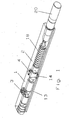
- FIG. 1 shows a door drive, which consists of a first housing 1 and a second housing 2, which are interconnected via a coupling 4.
- the basic components not shown, such as. B. Hubkurvenin with damping piston, a drive axle 3, and other hydraulic and mechanical components.
- the second housing 2 takes more drive components, such. B. compression spring 18, hydraulic piston, pump, motor or control, on. It is possible to construct the drive of more than two housings modular, which are then connected to a respective clutch 4.
- the second housing 2 not shown drive units such as pump / motor 20 or hydraulic block can be flanged.
- Parallel to the longitudinal axis 12 of the housing 1, 2 extend one or more hydraulic channels 13 which are connected via connectors 14 and sealed to the outside.
- the first housing 1 in FIG. 2 has a right-hand thread 1a and the second housing 2 has a left-hand thread 2a.
- the right-hand thread 1a engages in a complementary right-hand thread 4a of the coupling 4, and the left-hand thread 2a in a likewise complementary left-hand thread 4b of the coupling 4.
- left-hand and right-hand threads can be interchanged, it being important that the threads are arranged with opposite pitch
- First housing 1, coupling 4 and second housing 2 are penetrated in this embodiment by a piston rod 5.
- the coupling 4 has sealing grooves 4d, which can accommodate piston or sealing rings 7.
- On the outer diameter of the clutch 4 also sealing grooves 4c are incorporated, the sealing rings 6, such. B. round or radial seals, record.
- the piston rod 5 is connected in the second housing 2 via a pin 10 with a piston coupling 11, to which a piston, not shown, also a compression spring, not shown, is supported.
- a plunger for a compression spring or a drive spindle instead of the piston rod 5, a plunger for a compression spring or a drive spindle, the housing 1 and 2, as well as the clutch 4 penetrate.
- pin holes 8 are drilled, engage in the pin 9a of a tool 9.
- the number of pins 9a or pin holes 8 is usefully at least 2, preferably 4, which are evenly distributed on a circle around the central axis. Other positive power transmission means are also possible, such as a hexagon or the like.
- An assembly of the housings 1 and 2 is carried out as follows: the preassembled first housing 1 is positioned in a stationary manner.
- the piston rod 5 with attached piston coupling 11 is preassembled with the pin 10 and with the coupling 4 and the sealing rings 6, 7 outside the housing 1, 2. Then, this entire assembly is inserted into housing 1 and the connector 14 is inserted. About the protruding from the clutch 4 piston rod 5 with attached piston coupling 11, the housing 2 is pushed until the threads 1 a, 2 a of the housing 1, 2 with the threads 4 a, 4 b of the clutch 4 are engaged.
- the second housing 2 is aligned and fixed axially to the first housing 1, so that the second housing 2 can only perform an axial movement.
- a tool 9 is pushed, the pin 9a has.
- the pins 9 a engage in the pin holes 8 of the coupling 4.
- the clutch 4 rotates simultaneously in the right-hand thread 1a of the first housing 1 and in the left-hand thread 2a of the second housing 2, wherein the position and the angle assignment of the housing 1 and 2 remains unchanged to each other by the rotation of the Clutch 4 but axially along the longitudinal axis 12 to move toward each other.
- the clutch 4 is rotated until the housing 1 and 2 lie with their front sides on each other and are braced.
- the position of the housing 1 and 2 to each other is, even by the final fixation of the connector 14, remained unchanged.
- FIG. 3 a schematic representation of a door drive is shown in modular design, in which the second housing 2 accommodates the spring chamber and the spring adjustment device.
- the first housing integrates the basic components with, for example, the cam technology with Hubkurvenin 15 and pressure rollers or with the piston technology with internally toothed piston 17 and pinion 16.
- the first and second Housing 1, 2 are connected to the clutch 4.
- a pump / motor unit 20 can be flanged with or without hydraulic block.
Landscapes
- Power-Operated Mechanisms For Wings (AREA)
- Closing And Opening Devices For Wings, And Checks For Wings (AREA)
- Elevator Door Apparatuses (AREA)
- Electrical Discharge Machining, Electrochemical Machining, And Combined Machining (AREA)
- Steering Control In Accordance With Driving Conditions (AREA)
- Materials For Medical Uses (AREA)
- Dental Preparations (AREA)
Description
- Die Erfindung betrifft einen Türantrieb, der aus mehreren Komponenten, wie mechanischen, hydraulischen und elektrischen Antriebsaggregaten und/oder einem oder mehreren Gehäusen besteht, wobei die Komponenten miteinander verbunden sind.
- Ein Drehtürantrieb mit einer elektromechanischen Antriebseinheit ist aus der
DE 197 56 496 C2 bekannt. Dieser Drehtürantrieb weist eine offene Konstruktion ohne geschlossenes Gehäuse auf, wobei die einzelnen Komponenten hintereinander an einer Deckplatte bzw. an einer Abdeckung befestigt sind, die wiederum in das Türblatt eingelassen werden kann. So sind das Getriebe und der Antriebsmotor über eine Lagerhalterung an die Deckplatten angeflanscht. Bei größeren erforderlichen Drehmomenten fallen Getriebe und Motor in den Außenabmessungen deutlich größer aus, als dies in derFigur 1 derDE 197 56 496 C1 dargestellt ist. Die dort verwendete Flanschverbindung zwischen Getriebe und Deckplatte setzt voraus, dass entweder genügend Platz außerhalb des Durchmessers der Antriebskomponenten vorhanden ist, oder dass eine der Komponenten, wie in diesem Stand der Technik dargestellt, wenigstens in einem Bereich einen kleineren Außendurchmesser aufweist, als der Lochkreis der Flanschverbindung, damit für die Montage der Schraubenköpfe und/oder Muttern Platz vorhanden ist. Kommen weitere Komponenten wie z. B. eine Schließerfeder mit Gehäuse hinzu, um den Antrieb modulartig aufzubauen, entstehen lange Antriebe, bei denen eine ungewollte Lageabweichung der Achsen zu vorzeitigem Ausfall des gesamten Antriebes führen kann. Ein weiterer Nachteil dieses Standes der Technik ist, dass eine Schließerfeder als zusätzliches oder alternatives Bauteil zu den dort gezeigten Komponenten nicht verwendet werden kann, da die auftretenden Kräfte nicht von der Abdeckung aufgenommen werden können. Bei Verwendung von einem klassischen gegossenen Gehäuse, wie dies bei Türantrieben üblich ist, entstehen Gehäuselängen, die fast über die gesamte Türbreite reichen können. Bei den geforderten Abmessungen für den Einbau in die Tür ist eine vollständige Montage der Antriebskomponenten für eine Serienfertigung nicht mehr möglich. - Die
DE 19717993 A1 beschreibt einen automatischen Türantrieb, bei dem mehrere Rückstellvorrichtungen mittels Kupplung modulartig miteinander verbunden werden können.US-A-4 040 144 offenbart einen Türantrieb, der die Merkmale des Oberbegriffs des Anspruchs 1 aufweist. - Ebenfalls bekannt sind Türschließer, bei denen eine Grundkonstruktion mit verschiedenen Schließerfedern ausgestattet werden kann, um unterschiedliche Drehmomentverläufe zu erzielen. Hierzu werden die Schließerfedern mit einem Federgehäuse an den Türschließer angeschraubt, wobei das Federgehäuse an der Anschlußseite ein Innen- oder Außengewinde aufweist, das an ein komplementäres Gewinde am Türschließergehäuse eingeschraubt wird. Betrachtet man die Längsachse der Bauteile als Drehachse für das Eindrehen der Gewinde, so kann nicht exakt vorherbestimmt werden, in welcher Position das Federgehäuse am Türschließer zum Anliegen kommt. Hier besteht das Problem, dass keine exakte Lagezuordnung, insbesondere der Winkelanordnung der Gehäuse, möglich ist.
- Es ist daher Aufgabe der vorliegenden Erfindung, einen Türantrieb der im Oberbegriff des Anspruches 1 angegebenen Art zu schaffen, der aus mindestens zwei Komponenten besteht, die hinsichtlich ihrer Lagezuordnung exakt ausgerichtet und miteinander verbunden werden können.
- Die Lösung dieser Aufgabe wird durch die Merkmale des Anspruchs 1 offenbart, und erfolgt dadurch, dass zwei Komponenten mit einer Kupplung miteinander verbunden sind, wobei eine Komponente ein Rechtsgewinde aufweist, und die andere Komponente ein Linksgewinde aufweist, und dass Rechts- und Linksgewinde in komplementäre Gewinde der Kupplung eingreifen, wobei die kupplung zwei gehäuse verbindet. Damit kann, nachdem die Komponenten axial zueinander ausgerichtet wurden, durch Drehen der Kupplung ein Verspannen der Komponenten erfolgen, ohne dass eine axiale Abweichung oder eine Winkelabweichung entsteht.
- Als Komponenten werden Gehäuse oder Gehäuseteile, verstanden die die Pumpe, den Motor oder den Hydraulikblock aufnehmen können oder mit ihnen verbunden werden. So können mehrere Gehäuse miteinander verbunden werden, die die Pumpe, den Motor oder den Hydraulikblock aufnehmen. Es können aber auch Pumpe, Motor oder Hydraulikblock an einem Gehäuse befestigt werden, das wiederum weitere Antriebsaggregate und Antriebselemente aufnimmt. Als Hydraulikblock wird dabei im Wesentlichen die bauliche Zusammenfassung von Ventilen, Leitungen und/oder anderen hydraulischen Komponenten bezeichnet.
- Als Komponenten werden aber auch die Grundkomponenten eines Türschließers oder Türantriebes verstanden, die z.B. aus der Nockentechnologie mit Hubkurvenscheibe und Andrückrollen oder aus der Kolbentechnologie mit innenverzahntem Kolben und Ritzel bestehen kann. Diese Grundkomponenten sind in einem eigenen Gehäuse eingebaut und mittels der Kupplung mit den Antriebskomponenten je nach Anwendungsfall kombiniert. Da sowohl die Nockentechnologie wie auch die Kolbentechnologie je nach Anwendungsfall Vor- und Nachteile haben, kann mit Hilfe einer einheitlichen Baugruppe, in der Antriebsmotor, Hydraulikpumpe, Federraum und Federkraftverstellung integriert sind, die jeweils angemessene Technologie kombiniert werden. Die Kupplung schafft hierzu die Vorraussetzung, die verschiedenen Komponenten miteinander zu verbinden, die nur bei einer exakten Lagezuordnung störungsfrei zusammenarbeiten.
- Nach dieser Lösung kann die Kupplung die Funktion einer Überwurfmutter haben und von außen auf die Komponenten aufgeschraubt werden, oder - was hinsichtlich der Platzverhältnisse für den Einbau in die Tür von Vorteil ist - eine in eine - oder beide - Komponenten eingebaute Kupplung sein.
- Hierzu ist in bevorzugter Ausführungsform das Rechts- und Linksgewinde der Komponenten ein Innengewinde, und die komplementären Gewinde der Kupplung Außengewinde. Die Kupplung wird also in die Komponenten eingeschraubt.
- Die folgende Ausführung bezieht sich auf die Verwendung der Kupplung bei mindestens einem Gehäuse, das mit einem zweiten Gehäuseteil verbunden wird. Dabei kann in bevorzugter Ausführungsform die Kupplung innen eine Bohrung aufweisen und von einer Kolbenstange, einem Federstößel oder einer Spindel durchdrungen werden, so dass verschiedene Komponenten mit unterschiedlichen Funktionen modulartig miteinander verbunden werden können, und die Funktionen ineinander eingreifen.
- Die Kupplung ist zur Kolbenstange und zum Gehäuse mit Dichtungen abgedichtet, so dass in jedem Gehäuse ein separater Druckraum gebildet werden kann.
- Die Kupplung kann auf einer Stirnseite Zapfenlöcher aufweisen, in die die Zapfen eines Werkzeuges eingreifen. Damit kann ein Gehäuse komplett vormontiert werden und die Kupplung wird mit dem zweiten Gehäuse angesetzt. Das Werkzeug durchdringt das zweite Gehäuse und greift mit seinen Zapfen in die Zapfenlöcher der Kupplung ein, so dass durch Drehen des Werkzeuges die Kupplung gedreht wird und die Gehäuse sich axial auf den Gewinden aufeinander zu bewegen. Durch weiteres Drehen werden die Gehäuse verspannt, bis die Stirnseiten fest aufeinander liegen.
- Bei einem hydraulischen Türantrieb sind parallel zu einer Längsachse der Gehäuse hydraulische Kanäle in die Gehäuse eingearbeitet, die an den aufeinanderliegenden Stirnseiten der mit der Kupplung verbundenen Gehäuse miteinander fluchtend verbunden sind. Dadurch, dass die axiale Lage und die Winkelzuordnung der Gehäuse durch diese Kupplungsverbindung exakt gewährleistet ist, können die an den Stirnseiten der Gehäuse austretenden Kanäle und Leitungen mit geringem Aufwand nach außen zum Spalt zwischen den Gehäusen abgedichtet und miteinander verbunden werden. Ein nicht zu unterschätzender Vorteil ergibt sich in der Fertigung dieser Kanäle und Leitungen, da sehr tiefe Bohrungen immer sehr teuer in der Fertigung und ungenau in den Toleranzen sind. Durch Verwendung von mehreren Gehäusen oder dem Aufflanschen von Hydraulikblock oder Pumpe können die Bohrungen entlang der Längsachse für die hydraulischen Kanäle eine geringere Tiefe aufweisen, da durch die exakte axiale Lagezuordnung und Winkelzuordnung eine Verbindung der Kanäle über die Stirnseiten der Komponenten ohne Probleme möglich ist.
- Eine weitere Verbesserung ergibt sich, wenn in die aneinanderstoßenden offenen Hydraulikkanäle des ersten und zweiten Gehäuses Steckverbinder eingesetzt werden, die die Hydraulikkanäle nach außen abdichten. Die Steckverbinder übernehmen dabei gleichzeitig die Funktion der Lagefixierung der Gehäuse zueinander und nehmen einen Teil der Drehmomente auf, die beim Verschrauben der Gehäuse mit der Kupplung entstehen.
- Der erfindungsgemäße Türantrieb macht aufgrund seiner kompakten Bauweise einen unsichtbaren Einbau im Tür- oder Rahmenprofil und damit eine vollständige Integrierung in die Türanlage möglich. Insbesondere ist der Einbau in gängige schmale Türprofile möglich.
- Daraus ergibt sich der Vorteil, dass keine das Design der Türanlage beeinträchtigenden Spezialtürprofile und keine Sonderkonstruktionen notwendig sind. Ferner ergibt sich der Vorteil einer wirtschaftlichen Montage bei breiter Verwendbarkeit und überdies ist es möglich, bestehende Türanlagen mit dem erfindungsgemäßen Türantrieb nachzurüsten.
- Ein weiterer Vorteil besteht in der Verwendung von unterschiedlichen Komponentenwerkstoffen, die über die Kupplung miteinander verbunden werden. So kann ein Grundgehäuse mit der Dämpfung, der Hubkurvenscheibe und der Antriebsachse aus Grauguss oder Stahlguss hergestellt werden, und das ergänzende Gehäuseteil mit der Druckfeder aus Aluminium.
- Ein weiterer Vorteil ergibt sich in der leichten Montierbarkeit der Türantriebe, die jetzt erst in Serienfertigung möglich ist. Bei Verwendung der bisherigen gegossenen Gehäuse, die je nach Anwendungsfall einen Innendurchmesser von 20 bis 50 mm aufweisen, ist eine Montage der Antriebsaggregate bei einer Gehäuselänge von 500 bis 900 mm nicht mehr rationell möglich, da der Zeitaufwand bei Verwendung von Montagewerkzeugen, um in diese enge Bohrung zu gelangen, viel zu groß ist. Es ist damit eine Vormontage der Baugruppen außerhalb der Gehäusehälften möglich. Die Gehäuse können auf handelsüblichen Serienmaschinen gefertigt werden, was den Türantrieb preiswert macht, da keine Spezialmaschinen nötig sind und der Ausschuss bei den kürzeren Gehäuseteilen verringert wird.
- Ebenso ist es möglich, den Türantrieb entsprechend einem Baukastenprinzip mit verschiedenen Komponenten aufzubauen.
- Weitere Einzelheiten, Merkmale und Vorteile der Erfindung ergeben sich aus nachfolgender Beschreibung von Ausführungsbeispielen anhand der Zeichnungen.
- Es zeigen:
- Figur 1:
- Eine perspektivische Ansicht eines Türantriebes mit einem zweigeteilten Gehäuse und einer Kupplung,
- Figur 2:
- eine Schnittdarstellung durch den Bereich der Kupplung,
- Figur 3:
- eine schematische Darstellung eines Türantriebes in Modul- Bauweise.
-
Figur 1 zeigt einen Türantrieb, der aus einem ersten Gehäuse 1 und einem zweiten Gehäuse 2 besteht, die über eine Kupplung 4 miteinander verbunden sind. Im ersten Gehäuse 1 befinden sich die nicht dargestellten Grundkomponenten, wie z. B. Hubkurvenscheibe mit Dämpfungskolben, eine Antriebsachse 3, sowie weitere hydraulische und mechanische Bauteile. Über die Antriebsachse 3 wird der Türantrieb mittels nicht dargestelltem Hebel über ein Gleitstück und Gleitschiene mit einer Türzarge oder einer Wand verbunden. Alternativ ist, je nach Anwendungsfall, die Verwendung eines Scherengestänges möglich. Das zweite Gehäuse 2 nimmt weitere Antriebskomponenten, wie z. B. Druckfeder 18, Hydraulikkolben, Pumpe, Motor oder Steuerung, auf. Es ist dabei möglich, den Antrieb aus mehr als zwei Gehäusen modulartig aufzubauen, die dann mit je einer Kupplung 4 verbunden werden. Statt des zweiten Gehäuses 2 können auch nicht dargestellte Antriebsaggregate wie Pumpe/Motor 20 oder Hydraulikblock angeflanscht werden. Parallel zur Längsachse 12 der Gehäuse 1, 2 verlaufen einer oder mehrere Hydraulikkanäle 13, die über Steckverbinder 14 verbunden und nach außen abgedichtet werden. - Das erste Gehäuse 1 in
Figur 2 weist ein Rechtsgewinde 1a auf und das zweite Gehäuse 2 ein Linksgewinde 2a. Das Rechtsgewinde 1a greift in ein komplementäres Rechtsgewinde 4a der Kupplung 4 ein, und das Linksgewinde 2a in ein ebenfalls komplementäres Linksgewinde 4b der Kupplung 4. Links- und Rechtsgewinde können natürlich getauscht werden, wobei es wichtig ist, dass die Gewinde mit gegenläufiger Steigung angeordnet sind. Erstes Gehäuse 1, Kupplung 4 und zweites Gehäuse 2 werden in diesem Ausführungsbeispiel von einer Kolbenstange 5 durchdrungen. Die Kupplung 4 weist Dichtungsnuten 4d auf, die Kolben- oder Dichtringe 7 aufnehmen können. Auf dem Außendurchmesser der Kupplung 4 sind ebenfalls Dichtungsnuten 4c eingearbeitet, die Dichtringe 6, wie z. B. Rund- oder Radialdichtringe, aufnehmen können. Damit lassen sich über die Kupplung 4 die Druckräume der Gehäuse 1 und 2 voneinander trennen. Die Kolbenstange 5 ist in dem zweiten Gehäuse 2 über einen Stift 10 mit einer Kolbenkupplung 11 verbunden, an die sich über einen nicht dargestellten Kolben eine ebenfalls nicht dargestellte Druckfeder abstützt. Statt der Kolbenstange 5 kann auch ein Stößel für eine Druckfeder oder eine Antriebsspindel die Gehäuse 1 und 2, sowie die Kupplung 4 durchdringen. In eine Stirnseite der Kupplung 4 sind Zapfenlöcher 8 eingebohrt, in die Zapfen 9a eines Werkzeuges 9 eingreifen. Die Anzahl der Zapfen 9a bzw. Zapfenlöcher 8 ist Sinnvollerweise mindestens 2, bevorzugt 4, die gleichmäßig auf einem Kreis um die Mittelachse verteilt sind. Andere formschlüssige Kraftübertragungsmittel sind ebenfalls möglich, wie z.B. ein Sechskant oder ähnliches. - Eine Montage der Gehäuse 1 und 2 wird wie folgt durchgeführt: das vormontierte erste Gehäuse 1 wird ortsfest positioniert. Die Kolbenstange 5 mit angesetzter Kolbenkupplung 11 wird mit dem Stift 10 sowie mit der Kupplung 4 und den Dichtringen 6, 7 außerhalb der Gehäuse 1, 2 vormontiert. Dann wird diese gesamte Baugruppe in Gehäuse 1 eingesetzt und die Steckverbinder 14 eingesetzt. Über die aus der Kupplung 4 herausstehende Kolbenstange 5 mit daran befestigter Kolbenkupplung 11 wird das Gehäuse 2 geschoben, bis die Gewinde 1 a, 2a der Gehäuse 1, 2 mit den Gewinden 4a, 4b der Kupplung 4 in Eingriff kommen.
- Das zweite Gehäuse 2 wird axial zum ersten Gehäuse 1 ausgerichtet und fixiert, so dass das zweite Gehäuse 2 nur noch eine axiale Bewegung ausführen kann. Durch das zweite Gehäuse 2 wird ein Werkzeug 9 geschoben, das Zapfen 9a aufweist. Die Zapfen 9a greifen in die Zapfenlöcher 8 der Kupplung 4 ein. Durch Drehen des Werkzeuges 9 dreht sich die Kupplung 4 gleichzeitig in das Rechtsgewinde 1a des ersten Gehäuses 1 und in das Linksgewinde 2a des zweiten Gehäuses 2, wobei die Lage- und die Winkelzuordnung der Gehäuse 1 und 2 zueinander unverändert bleibt, sich durch die Drehung der Kupplung 4 aber axial entlang der Längsachse 12 aufeinander zu bewegen. Die Kupplung 4 wird solange gedreht, bis die Gehäuse 1 und 2 mit ihren Stirnseiten aufeinander liegen und verspannt sind. Die Lage der Gehäuse 1 und 2 zueinander ist dabei, auch durch die abschließende Fixierung der Steckverbinder 14, unverändert geblieben.
- Insbesondere bei hydraulischen Antrieben, bei denen die Gehäuse lange, parallel zur Längsachse angeordnete Bohrungen als Hydraulikkanäle aufweisen, ist die exakte Positionierung und Winkellage sehr wichtig. Da lange, gebohrte Kanäle die Tendenz haben, aus der geplanten Bohrachse zu verlaufen, können mit getrennten Gehäusen die Kanäle kürzer und damit fertigungstechnisch preiswerter hergestellt werden. Die bisherigen Lösungen, hydraulische Leitungen und Kanäle quasi wie einen Bremsschlauch auf dem Gehäuse zu verlegen, um die langen Bohrungen zu vermeiden, scheitert bei den Türantrieben, die in die Tür integriert werden, am vorhandenen Einbauraum. Die Erfindung schafft damit erstmals die Möglichkeit, hydraulische Türantrieb mit geteilten oder mehreren Gehäusen so zu verbinden, dass die in das Gehäuse integrierten Kanäle oder Leitungen wie eine durchgehende hydraulische Leitung wirken. Durch die radiale Abdichtung von Kupplung und Steckverbinder ist keine Stirn- bzw. Flachdichtung erforderlich.
- In
Figur 3 wird eine schematische Darstellung eines Türantriebes in Modulbauweise gezeigt, bei der das zweite Gehäuse 2 den Federraum und die Federverstellvorrichtung aufnimmt. Das erste Gehäuse integriert die Grundkomponenten mit z.B. der Nockentechnologie mit Hubkurvenscheibe 15 und Andrückrollen oder mit der Kolbentechnologie mit innenverzahntem Kolben 17 und Ritzel 16. Je nach verwendeter Grundkomponente werden in das zweite Gehäuse 2 dazu passende Federn 18 oder 19 eingebaut. Das erste und zweite Gehäuse 1, 2 werden dabei mit der Kupplung 4 verbunden. Am anderen Ende des zweiten Gehäuses 2 kann eine Pumpe-/Motoreinheit 20 mit oder ohne Hydraulikblock angeflanscht werden. -
- 1
- erstes Gehäuse
- 1 a
- Rechtsgewinde
- 2
- zweites Gehäuse
- 2a
- Linksgewinde
- 3
- Antriebsachse
- 4
- Kupplung
- 4a
- Rechtsgewinde
- 4b
- Linksgewinde
- 4c
- Dichtungsnut
- 4d
- Dichtungsnut
- 5
- Kolbenstange
- 6
- Dichtring
- 7
- Dichtring
- 8
- Zapfenloch
- 9
- Werkzeug
- 9a
- Zapfen
- 10
- Stift
- 11
- Kolbenkupplung
- 12
- Längsachse
- 13
- Hydraulikkanal
- 14
- Steckverbinder
- 15
- Hubkurvenscheibe
- 16
- Ritzel
- 17
- innenverzahnter Kolben
- 18
- Druckfeder
- 19
- Druckfeder
- 20
- Pumpe/Motor
Claims (10)
- Türantrieb, bestehend aus mehreren, ein Gewinde (1a, 2a) aufweisenden, Komponenten (1, 2), wie mechanischen, hydraulischen und elektrischen Antriebsaggregaten und/oder einem oder mehreren Gehäusen (1, 2), wobei mindestens zwei Komponenten (1, 2) mit einer drehbaren, ein zum genannten Gewinde (1a, 2a) komplementäre Gewinde (4a, 4b) aufweisenden, Kupplung (4) miteinander verbunden sind, dadurch gekennzeichnet, dass eine Komponente (1) ein Rechtsgewinde (1a) aufweist, und die andere Komponente (2) ein Linksgewinde (2a) aufweist, und dass Rechts- und Linksgewinde (1a, 2a) in das komplementäre Rechts- bzw Linksgewinde (4a, 4b) der Kupplung (4) eingreifen, wobei die Kupplung (4) zwei Gehäuse (1,2) verbindet.
- Türantrieb nach Anspruch 1, dadurch gekennzeichnet, dass das Rechts- und Linksgewinde (1a, 2a) der Komponenten ein Innengewinde ist, und die komplementären Gewinde (4a, 4b) der Kupplung (4) Außengewinde sind.
- Türantrieb nach Anspruch 1, dadurch gekennzeichnet, dass das erste Gehäuse (1) wahlweise mechanische Elemente für die Nockentechnologie oder die Kolbentechnologie aufnimmt, und in oder an dem zweiten Gehäuse (2) der Federraum und/oder die Federkraftverstellung und/oder der Antriebsmotor und/oder die Hydraulikpumpe angeordnet sind.
- Türantrieb nach Anspruch 1, dadurch gekennzeichnet, dass die Kupplung (4) von einer Kolbenstange (5), oder einem Federstößel oder einer Spindel durchdrungen wird.
- Türantrieb, nach einem der vorhergehenden Ansprüche, dadurch gekennzeichnet, dass die Kupplung (4) mindestens eine Dichtungsnut (4d) für einen Dichtring (7) aufweist, mit dem eine Abdichtung der Kolbenstange (5), dem Federstößel oder der Spindel zum Gehäuse (1) und/oder Gehäuse (2) erfolgt.
- Türantrieb nach einem der vorhergehenden Ansprüche, dadurch gekennzeichnet, dass die Kupplung (4) mindestens eine Dichtungsnut (4c) für einen Dichtring (6) aufweist, mit dem eine Abdichtung der Kupplung (4) zum Gehäuse (1) und/oder Gehäuse (2) erfolgt.
- Türantrieb nach einem der vorhergehenden Ansprüche, dadurch gekennzeichnet, dass die Kupplung (4) auf einer Stirnseite Zapfenlöcher (8) aufweist, in die die Zapfen (9a) eines Werkzeuges (9) eingreifen.
- Türantrieb nach einem der vorhergehenden Ansprüche, dadurch gekennzeichnet, dass parallel zu einer Längsachse (12) der Gehäuse (1, 2) mindestens ein Hydraulikkanal (13) durch das erste und das zweite Gehäuse (1, 2) verläuft, der an den aufeinanderliegenden Stirnseiten der mit der Kupplung (4) verbundenen Gehäuse (1, 2) miteinander fluchtend verbunden ist.
- Türantrieb nach Anspruch 8, dadurch gekennzeichnet, dass der Hydraulikkanal (13) des ersten Gehäuses (1) mit dem Hydraulikkanal (13) des zweiten Gehäuses (2) im Bereich der aufeinanderliegenden Stirnseiten der Gehäuse (1, 2) mittels Steckverbinder (14) miteinander verbunden sind.
- Türantrieb nach einem der vorhergehenden Ansprüche, dadurch gekennzeichnet, dass der Türantrieb ein hydraulischer Türantrieb ist.
Applications Claiming Priority (2)
| Application Number | Priority Date | Filing Date | Title |
|---|---|---|---|
| DE102004061622A DE102004061622B4 (de) | 2004-12-17 | 2004-12-17 | Türantrieb |
| PCT/EP2005/012089 WO2006066661A1 (de) | 2004-12-17 | 2005-11-11 | Tuerantrieb |
Publications (3)
| Publication Number | Publication Date |
|---|---|
| EP1828516A1 EP1828516A1 (de) | 2007-09-05 |
| EP1828516B1 EP1828516B1 (de) | 2010-05-12 |
| EP1828516B2 true EP1828516B2 (de) | 2016-03-09 |
Family
ID=35589629
Family Applications (1)
| Application Number | Title | Priority Date | Filing Date |
|---|---|---|---|
| EP05806642.4A Expired - Lifetime EP1828516B2 (de) | 2004-12-17 | 2005-11-11 | Tuerantrieb |
Country Status (8)
| Country | Link |
|---|---|
| US (1) | US8393054B2 (de) |
| EP (1) | EP1828516B2 (de) |
| CN (2) | CN104818917A (de) |
| AT (1) | ATE467743T1 (de) |
| DE (2) | DE102004061622B4 (de) |
| DK (1) | DK1828516T3 (de) |
| ES (1) | ES2345266T5 (de) |
| WO (1) | WO2006066661A1 (de) |
Families Citing this family (32)
| Publication number | Priority date | Publication date | Assignee | Title |
|---|---|---|---|---|
| DE102007038844A1 (de) * | 2007-08-16 | 2009-02-19 | Dorma Gmbh + Co. Kg | Linearantrieb für Schiebetüren oder dergleichen |
| CH706425A1 (de) * | 2012-04-23 | 2013-10-31 | Gilgen Door Systems Ag | Drehantrieb für mindestens einen Flügel, insbesondere eine Türe oder ein Fenster. |
| DE102012111536A1 (de) * | 2012-11-28 | 2014-05-28 | Dorma Gmbh + Co. Kg | Türbetätiger |
| USD715129S1 (en) * | 2013-09-05 | 2014-10-14 | Hampton Products International Corporation | Spring housing for a door closing device |
| EP2933410A1 (de) * | 2014-04-15 | 2015-10-21 | GEZE GmbH | Türantrieb |
| CA2991660A1 (en) * | 2015-07-23 | 2017-01-26 | Gotthard 3 Mechatronic Solutions AG | Drive for a rotatable wing |
| US10900274B2 (en) | 2016-09-02 | 2021-01-26 | Pella Corporation | Anti-rattle elements for internal divider of glass assembly |
| US10876343B2 (en) | 2016-12-08 | 2020-12-29 | Pella Corporation | Casement sliding operator |
| US11454055B2 (en) | 2017-01-20 | 2022-09-27 | Pella Corporation | Window opening control systems and methods |
| DE102019100751A1 (de) * | 2018-01-15 | 2019-07-18 | Magna Closures Inc. | Verschlusspaneel-Extensionsmechanismus mit mehreren Federn |
| EP3867475B1 (de) * | 2018-10-15 | 2024-06-05 | OL.MI Srl | Scharnier für die gesteuerte drehbewegung einer tür, eines türblatts oder dergleichen |
| IT201800009455A1 (it) * | 2018-10-15 | 2020-04-15 | Olmi Srl | Cerniera per la movimentazione girevole controllata di una porta, un’anta o similare |
| CA3060764C (en) | 2018-10-31 | 2022-08-23 | Pella Corporation | Slide operator for fenestration unit |
| CA3081316C (en) | 2019-05-24 | 2022-09-06 | Pella Corporation | Slide operator assemblies and components for fenestration units |
| US11414911B2 (en) | 2020-01-24 | 2022-08-16 | Overhead Door Corporation | Swing door operator with offset spring |
| TWI769855B (zh) | 2021-06-11 | 2022-07-01 | 一德金屬工業股份有限公司 | 利用即時無線供電的鎖具的解鎖方法 |
| TWI802033B (zh) | 2021-10-06 | 2023-05-11 | 一德金屬工業股份有限公司 | 簡易安裝的門弓器 |
| TWI776725B (zh) | 2021-11-03 | 2022-09-01 | 一德金屬工業股份有限公司 | 門弓器 |
| TWI810821B (zh) | 2022-02-18 | 2023-08-01 | 一德金屬工業股份有限公司 | 具有離合器的鎖具 |
| US12410650B2 (en) | 2022-02-25 | 2025-09-09 | Overhead Door Corporation | Swing door operator |
| TWI789280B (zh) | 2022-03-28 | 2023-01-01 | 一德金屬工業股份有限公司 | 簡便拆裝輸入介面電子模組的門鎖 |
| TWI790170B (zh) | 2022-05-23 | 2023-01-11 | 一德金屬工業股份有限公司 | 可電動上鎖與解鎖的門鎖 |
| TWI815529B (zh) | 2022-06-29 | 2023-09-11 | 一德金屬工業股份有限公司 | 電動控制門鎖 |
| TWI828294B (zh) | 2022-08-31 | 2024-01-01 | 一德金屬工業股份有限公司 | 具有防鬆脫連桿組的門弓器 |
| TWI828293B (zh) | 2022-08-31 | 2024-01-01 | 一德金屬工業股份有限公司 | 能控制關門速度的門弓器 |
| TWI798156B (zh) | 2022-09-23 | 2023-04-01 | 一德金屬工業股份有限公司 | 具防撬功能的鎖匣 |
| TWI821011B (zh) | 2022-11-10 | 2023-11-01 | 一德金屬工業股份有限公司 | 可連動防盜閂的鎖匣 |
| TWI815753B (zh) | 2022-12-19 | 2023-09-11 | 一德金屬工業股份有限公司 | 重型鎖匣 |
| TWI885339B (zh) | 2023-03-07 | 2025-06-01 | 一德金屬工業股份有限公司 | 密碼式鎖具的管控方法 |
| TWI854632B (zh) | 2023-05-04 | 2024-09-01 | 一德金屬工業股份有限公司 | 可緊急通報的門禁管制方法 |
| TWI880445B (zh) | 2023-11-10 | 2025-04-11 | 一德金屬工業股份有限公司 | 發生槍擊事件時的各人員定位與追蹤方法 |
| TWI891328B (zh) | 2024-04-18 | 2025-07-21 | 一德金屬工業股份有限公司 | 適用車輛的門禁管制方法 |
Citations (6)
| Publication number | Priority date | Publication date | Assignee | Title |
|---|---|---|---|---|
| DE2737666A1 (de) † | 1977-08-20 | 1979-02-22 | Ver Baubeschlag Gretsch Co | Drehlageranordnung |
| DE3840096A1 (de) † | 1988-11-28 | 1990-05-31 | Wiederaufarbeitung Von Kernbre | Absturzsichere hubeinrichtung |
| EP0328934B1 (de) † | 1988-02-13 | 1992-01-02 | Gretsch-Unitas GmbH Baubeschläge | Türschliesser |
| DE4201174A1 (de) † | 1992-01-17 | 1993-07-22 | Erich Doering | Torantrieb fuer ein schwingtor, sektionaltor oder schiebetor, insbesondere garagentor |
| DE10033304C1 (de) † | 2000-07-04 | 2002-09-05 | Joerg Cruel | Verbindersystem für Bauelemente und Möbelkonstruktionen |
| DE10321287A1 (de) † | 2002-05-14 | 2003-11-27 | Luk Lamellen & Kupplungsbau | Hydraulisches System |
Family Cites Families (12)
| Publication number | Priority date | Publication date | Assignee | Title |
|---|---|---|---|---|
| US1063790A (en) * | 1911-06-26 | 1913-06-03 | Walter Anthony Greaves | Center-shaft head. |
| US1429982A (en) * | 1921-02-15 | 1922-09-26 | Igoe Brothers | Shaft coupling |
| US3852846A (en) * | 1972-07-28 | 1974-12-10 | Republic Industries | Door hold open attachment for a door check |
| DE2520958A1 (de) * | 1975-05-10 | 1976-11-18 | Hans Baumgartner & Co Zollikon | Antriebsvorrichtung mit hydraulischer bremsvorrichtung fuer tueren |
| US4040144A (en) * | 1976-05-24 | 1977-08-09 | Schlage Lock Company | Door assister |
| US4870961A (en) * | 1986-09-22 | 1989-10-03 | Barnard Gordon D | Medical ventilator tube and manifold assembly |
| US5474334A (en) * | 1994-08-02 | 1995-12-12 | Halliburton Company | Coupling assembly |
| US5488896A (en) * | 1994-12-22 | 1996-02-06 | Schlage Lock Company | Self aligning piston rod |
| DE19717993A1 (de) * | 1997-04-28 | 1998-10-29 | Geze Gmbh & Co | Vorrichtung zum automatischen Öffnen und/oder Schließen und/oder zum Dämpfen eines Flügels einer Tür, eines Fensters o. dgl. |
| DE19756496C2 (de) * | 1997-12-19 | 2000-07-06 | Dorma Gmbh & Co Kg | Drehtürantrieb |
| CN2554304Y (zh) * | 2002-07-03 | 2003-06-04 | 许继集团有限公司 | 丝杠式车库门驱动器 |
| US6904643B2 (en) * | 2003-02-27 | 2005-06-14 | Tom W. Duffy | Door closer hold-open apparatus |
-
2004
- 2004-12-17 DE DE102004061622A patent/DE102004061622B4/de not_active Expired - Lifetime
-
2005
- 2005-11-11 ES ES05806642.4T patent/ES2345266T5/es not_active Expired - Lifetime
- 2005-11-11 WO PCT/EP2005/012089 patent/WO2006066661A1/de not_active Ceased
- 2005-11-11 AT AT05806642T patent/ATE467743T1/de active
- 2005-11-11 CN CN201410690712.0A patent/CN104818917A/zh active Pending
- 2005-11-11 DE DE502005009572T patent/DE502005009572D1/de not_active Expired - Lifetime
- 2005-11-11 DK DK05806642.4T patent/DK1828516T3/da active
- 2005-11-11 EP EP05806642.4A patent/EP1828516B2/de not_active Expired - Lifetime
- 2005-11-11 CN CN200580043268.2A patent/CN101080542A/zh active Pending
- 2005-11-11 US US11/793,068 patent/US8393054B2/en active Active
Patent Citations (6)
| Publication number | Priority date | Publication date | Assignee | Title |
|---|---|---|---|---|
| DE2737666A1 (de) † | 1977-08-20 | 1979-02-22 | Ver Baubeschlag Gretsch Co | Drehlageranordnung |
| EP0328934B1 (de) † | 1988-02-13 | 1992-01-02 | Gretsch-Unitas GmbH Baubeschläge | Türschliesser |
| DE3840096A1 (de) † | 1988-11-28 | 1990-05-31 | Wiederaufarbeitung Von Kernbre | Absturzsichere hubeinrichtung |
| DE4201174A1 (de) † | 1992-01-17 | 1993-07-22 | Erich Doering | Torantrieb fuer ein schwingtor, sektionaltor oder schiebetor, insbesondere garagentor |
| DE10033304C1 (de) † | 2000-07-04 | 2002-09-05 | Joerg Cruel | Verbindersystem für Bauelemente und Möbelkonstruktionen |
| DE10321287A1 (de) † | 2002-05-14 | 2003-11-27 | Luk Lamellen & Kupplungsbau | Hydraulisches System |
Also Published As
| Publication number | Publication date |
|---|---|
| DE502005009572D1 (de) | 2010-06-24 |
| DE102004061622A1 (de) | 2006-07-06 |
| CN104818917A (zh) | 2015-08-05 |
| EP1828516A1 (de) | 2007-09-05 |
| ATE467743T1 (de) | 2010-05-15 |
| CN101080542A (zh) | 2007-11-28 |
| EP1828516B1 (de) | 2010-05-12 |
| DK1828516T3 (da) | 2010-08-23 |
| ES2345266T3 (es) | 2010-09-20 |
| US20080092446A1 (en) | 2008-04-24 |
| US8393054B2 (en) | 2013-03-12 |
| WO2006066661A1 (de) | 2006-06-29 |
| DE102004061622B4 (de) | 2013-07-18 |
| ES2345266T5 (es) | 2016-06-20 |
Similar Documents
| Publication | Publication Date | Title |
|---|---|---|
| EP1828516B2 (de) | Tuerantrieb | |
| DE19756496C2 (de) | Drehtürantrieb | |
| EP2909399B1 (de) | System mit türbetätigungsteil und schliesszylinder | |
| DE102012001700B4 (de) | Zweispindelige Schraubenspindelpumpe in einflutiger Bauweise | |
| DE102010002625B4 (de) | Hydraulische Stelleinrichtung für einen Türflügel eines Omnibusses | |
| EP2025852A1 (de) | Motorisch angetriebener Linearaktuator | |
| DE102011054079A1 (de) | Drehflügelbetätiger und Montage desselben | |
| DE19506355C2 (de) | Selbsttätiger Türschließer | |
| WO2016141937A1 (de) | Linearer stellantrieb und verfahren zur montage eines stellantriebs | |
| EP2933414A1 (de) | Türantrieb | |
| EP1835110B1 (de) | Türbetätigungsvorrichtung, insbesondere für eine Drehtür | |
| DE2812927A1 (de) | Zwischenplatte fuer ein hydraulisches verkettungssystem | |
| EP0492175B1 (de) | Türschliesser | |
| EP3800315B1 (de) | Antriebsmodul zum verlagern eines verschlusselements relativ zu einem rahmen in einer gebäudeöffnung | |
| WO2012110013A1 (de) | Aufsatz für schwenktürbetätiger | |
| DE102005058843A1 (de) | Zwischenblech einer elektrohydraulischen Steuervorrichtung | |
| DE102012208495B4 (de) | Nockenwellenversteller | |
| EP0256254A1 (de) | Steuereinrichtung für die Verstellung des Einspritzzeitpunktes und/oder der Fördermenge einer Kraftstoffeinspritzpumpe | |
| EP2402638B1 (de) | Verbindungsanordnung zum Verbinden zweier Bauteile | |
| DE2508268C3 (de) | Steuerkolben fur hydraulische Druckmittelfolgesteuerungen, insbesondere für ein Lenkventil einer Servolenkeinrichtung von Fahrzeugen | |
| DE102015202832B3 (de) | Türantrieb | |
| WO2020169309A1 (de) | Kugelgewindetrieb mit verdrehsicherung | |
| DE102024107399B3 (de) | Antrieb für eine Tür oder ein Fenster mit verbessertem Wirkungsgrad | |
| EP2832946A1 (de) | Hebel für einen Türbetätiger | |
| DE102012111534A1 (de) | Türbetätiger |
Legal Events
| Date | Code | Title | Description |
|---|---|---|---|
| PUAI | Public reference made under article 153(3) epc to a published international application that has entered the european phase |
Free format text: ORIGINAL CODE: 0009012 |
|
| 17P | Request for examination filed |
Effective date: 20070717 |
|
| AK | Designated contracting states |
Kind code of ref document: A1 Designated state(s): AT BE BG CH CY CZ DE DK EE ES FI FR GB GR HU IE IS IT LI LT LU LV MC NL PL PT RO SE SI SK TR |
|
| 17Q | First examination report despatched |
Effective date: 20071012 |
|
| DAX | Request for extension of the european patent (deleted) | ||
| GRAP | Despatch of communication of intention to grant a patent |
Free format text: ORIGINAL CODE: EPIDOSNIGR1 |
|
| GRAS | Grant fee paid |
Free format text: ORIGINAL CODE: EPIDOSNIGR3 |
|
| GRAA | (expected) grant |
Free format text: ORIGINAL CODE: 0009210 |
|
| AK | Designated contracting states |
Kind code of ref document: B1 Designated state(s): AT BE BG CH CY CZ DE DK EE ES FI FR GB GR HU IE IS IT LI LT LU LV MC NL PL PT RO SE SI SK TR |
|
| REG | Reference to a national code |
Ref country code: GB Ref legal event code: FG4D Free format text: NOT ENGLISH |
|
| REG | Reference to a national code |
Ref country code: CH Ref legal event code: EP |
|
| REG | Reference to a national code |
Ref country code: IE Ref legal event code: FG4D Free format text: LANGUAGE OF EP DOCUMENT: GERMAN |
|
| REF | Corresponds to: |
Ref document number: 502005009572 Country of ref document: DE Date of ref document: 20100624 Kind code of ref document: P |
|
| REG | Reference to a national code |
Ref country code: CH Ref legal event code: NV Representative=s name: BOVARD AG PATENTANWAELTE |
|
| RAP2 | Party data changed (patent owner data changed or rights of a patent transferred) |
Owner name: DORMA GMBH + CO. KG |
|
| REG | Reference to a national code |
Ref country code: SE Ref legal event code: TRGR |
|
| REG | Reference to a national code |
Ref country code: DK Ref legal event code: T3 |
|
| REG | Reference to a national code |
Ref country code: NL Ref legal event code: VDEP Effective date: 20100512 |
|
| REG | Reference to a national code |
Ref country code: ES Ref legal event code: FG2A Ref document number: 2345266 Country of ref document: ES Kind code of ref document: T3 |
|
| LTIE | Lt: invalidation of european patent or patent extension |
Effective date: 20100512 |
|
| PG25 | Lapsed in a contracting state [announced via postgrant information from national office to epo] |
Ref country code: LT Free format text: LAPSE BECAUSE OF FAILURE TO SUBMIT A TRANSLATION OF THE DESCRIPTION OR TO PAY THE FEE WITHIN THE PRESCRIBED TIME-LIMIT Effective date: 20100512 Ref country code: NL Free format text: LAPSE BECAUSE OF FAILURE TO SUBMIT A TRANSLATION OF THE DESCRIPTION OR TO PAY THE FEE WITHIN THE PRESCRIBED TIME-LIMIT Effective date: 20100512 |
|
| PG25 | Lapsed in a contracting state [announced via postgrant information from national office to epo] |
Ref country code: SI Free format text: LAPSE BECAUSE OF FAILURE TO SUBMIT A TRANSLATION OF THE DESCRIPTION OR TO PAY THE FEE WITHIN THE PRESCRIBED TIME-LIMIT Effective date: 20100512 Ref country code: LV Free format text: LAPSE BECAUSE OF FAILURE TO SUBMIT A TRANSLATION OF THE DESCRIPTION OR TO PAY THE FEE WITHIN THE PRESCRIBED TIME-LIMIT Effective date: 20100512 Ref country code: IS Free format text: LAPSE BECAUSE OF FAILURE TO SUBMIT A TRANSLATION OF THE DESCRIPTION OR TO PAY THE FEE WITHIN THE PRESCRIBED TIME-LIMIT Effective date: 20100912 |
|
| PG25 | Lapsed in a contracting state [announced via postgrant information from national office to epo] |
Ref country code: PL Free format text: LAPSE BECAUSE OF FAILURE TO SUBMIT A TRANSLATION OF THE DESCRIPTION OR TO PAY THE FEE WITHIN THE PRESCRIBED TIME-LIMIT Effective date: 20100512 Ref country code: GR Free format text: LAPSE BECAUSE OF FAILURE TO SUBMIT A TRANSLATION OF THE DESCRIPTION OR TO PAY THE FEE WITHIN THE PRESCRIBED TIME-LIMIT Effective date: 20100813 Ref country code: CY Free format text: LAPSE BECAUSE OF FAILURE TO SUBMIT A TRANSLATION OF THE DESCRIPTION OR TO PAY THE FEE WITHIN THE PRESCRIBED TIME-LIMIT Effective date: 20100512 |
|
| PG25 | Lapsed in a contracting state [announced via postgrant information from national office to epo] |
Ref country code: PT Free format text: LAPSE BECAUSE OF FAILURE TO SUBMIT A TRANSLATION OF THE DESCRIPTION OR TO PAY THE FEE WITHIN THE PRESCRIBED TIME-LIMIT Effective date: 20100913 Ref country code: EE Free format text: LAPSE BECAUSE OF FAILURE TO SUBMIT A TRANSLATION OF THE DESCRIPTION OR TO PAY THE FEE WITHIN THE PRESCRIBED TIME-LIMIT Effective date: 20100512 |
|
| PLBI | Opposition filed |
Free format text: ORIGINAL CODE: 0009260 |
|
| PG25 | Lapsed in a contracting state [announced via postgrant information from national office to epo] |
Ref country code: SK Free format text: LAPSE BECAUSE OF FAILURE TO SUBMIT A TRANSLATION OF THE DESCRIPTION OR TO PAY THE FEE WITHIN THE PRESCRIBED TIME-LIMIT Effective date: 20100512 Ref country code: CZ Free format text: LAPSE BECAUSE OF FAILURE TO SUBMIT A TRANSLATION OF THE DESCRIPTION OR TO PAY THE FEE WITHIN THE PRESCRIBED TIME-LIMIT Effective date: 20100512 Ref country code: RO Free format text: LAPSE BECAUSE OF FAILURE TO SUBMIT A TRANSLATION OF THE DESCRIPTION OR TO PAY THE FEE WITHIN THE PRESCRIBED TIME-LIMIT Effective date: 20100512 |
|
| PLAX | Notice of opposition and request to file observation + time limit sent |
Free format text: ORIGINAL CODE: EPIDOSNOBS2 |
|
| 26 | Opposition filed |
Opponent name: GEZE GMBH Effective date: 20110211 |
|
| PLBB | Reply of patent proprietor to notice(s) of opposition received |
Free format text: ORIGINAL CODE: EPIDOSNOBS3 |
|
| REG | Reference to a national code |
Ref country code: CH Ref legal event code: PFA Owner name: DORMA GMBH + CO. KG Free format text: DORMA GMBH + CO. KG#DORMA PLATZ 1#58256 ENNEPETAL (DE) -TRANSFER TO- DORMA GMBH + CO. KG#DORMA PLATZ 1#58256 ENNEPETAL (DE) |
|
| REG | Reference to a national code |
Ref country code: DE Ref legal event code: R026 Ref document number: 502005009572 Country of ref document: DE Effective date: 20110211 |
|
| BERE | Be: lapsed |
Owner name: DORMA G.M.B.H. & CO. KG Effective date: 20101130 |
|
| PG25 | Lapsed in a contracting state [announced via postgrant information from national office to epo] |
Ref country code: MC Free format text: LAPSE BECAUSE OF NON-PAYMENT OF DUE FEES Effective date: 20101130 |
|
| PG25 | Lapsed in a contracting state [announced via postgrant information from national office to epo] |
Ref country code: BE Free format text: LAPSE BECAUSE OF NON-PAYMENT OF DUE FEES Effective date: 20101130 |
|
| PG25 | Lapsed in a contracting state [announced via postgrant information from national office to epo] |
Ref country code: HU Free format text: LAPSE BECAUSE OF FAILURE TO SUBMIT A TRANSLATION OF THE DESCRIPTION OR TO PAY THE FEE WITHIN THE PRESCRIBED TIME-LIMIT Effective date: 20101113 Ref country code: LU Free format text: LAPSE BECAUSE OF NON-PAYMENT OF DUE FEES Effective date: 20101111 Ref country code: BG Free format text: LAPSE BECAUSE OF FAILURE TO SUBMIT A TRANSLATION OF THE DESCRIPTION OR TO PAY THE FEE WITHIN THE PRESCRIBED TIME-LIMIT Effective date: 20100512 |
|
| PG25 | Lapsed in a contracting state [announced via postgrant information from national office to epo] |
Ref country code: TR Free format text: LAPSE BECAUSE OF FAILURE TO SUBMIT A TRANSLATION OF THE DESCRIPTION OR TO PAY THE FEE WITHIN THE PRESCRIBED TIME-LIMIT Effective date: 20100512 |
|
| PG25 | Lapsed in a contracting state [announced via postgrant information from national office to epo] |
Ref country code: BG Free format text: LAPSE BECAUSE OF FAILURE TO SUBMIT A TRANSLATION OF THE DESCRIPTION OR TO PAY THE FEE WITHIN THE PRESCRIBED TIME-LIMIT Effective date: 20100812 |
|
| PLAB | Opposition data, opponent's data or that of the opponent's representative modified |
Free format text: ORIGINAL CODE: 0009299OPPO |
|
| R26 | Opposition filed (corrected) |
Opponent name: GEZE GMBH Effective date: 20110211 |
|
| PGFP | Annual fee paid to national office [announced via postgrant information from national office to epo] |
Ref country code: DK Payment date: 20131120 Year of fee payment: 9 |
|
| PGFP | Annual fee paid to national office [announced via postgrant information from national office to epo] |
Ref country code: CH Payment date: 20131121 Year of fee payment: 9 Ref country code: IE Payment date: 20131126 Year of fee payment: 9 Ref country code: SE Payment date: 20131121 Year of fee payment: 9 |
|
| REG | Reference to a national code |
Ref country code: DE Ref legal event code: R081 Ref document number: 502005009572 Country of ref document: DE Owner name: DORMAKABA DEUTSCHLAND GMBH, DE Free format text: FORMER OWNER: DORMA GMBH & CO. KG, 58256 ENNEPETAL, DE Effective date: 20141210 Ref country code: DE Ref legal event code: R081 Ref document number: 502005009572 Country of ref document: DE Owner name: DORMA DEUTSCHLAND GMBH, DE Free format text: FORMER OWNER: DORMA GMBH & CO. KG, 58256 ENNEPETAL, DE Effective date: 20141210 |
|
| REG | Reference to a national code |
Ref country code: FR Ref legal event code: CJ Effective date: 20150206 |
|
| REG | Reference to a national code |
Ref country code: ES Ref legal event code: PC2A Owner name: DORMA DEUTSCHLAND GMBH Effective date: 20150415 |
|
| REG | Reference to a national code |
Ref country code: DE Ref legal event code: R082 Ref document number: 502005009572 Country of ref document: DE Representative=s name: BALDER IP LAW, S.L., ES |
|
| REG | Reference to a national code |
Ref country code: DK Ref legal event code: EBP Effective date: 20141130 |
|
| RAP2 | Party data changed (patent owner data changed or rights of a patent transferred) |
Owner name: DORMA DEUTSCHLAND GMBH |
|
| REG | Reference to a national code |
Ref country code: SE Ref legal event code: EUG Ref country code: CH Ref legal event code: PL |
|
| RIC2 | Information provided on ipc code assigned after grant |
Ipc: E05F 3/00 20060101AFI20150610BHEP Ipc: E05F 3/22 20060101ALI20150610BHEP Ipc: E05F 3/10 20060101ALI20150610BHEP Ipc: E05F 15/611 20150101ALI20150610BHEP |
|
| PG25 | Lapsed in a contracting state [announced via postgrant information from national office to epo] |
Ref country code: LI Free format text: LAPSE BECAUSE OF NON-PAYMENT OF DUE FEES Effective date: 20141130 Ref country code: CH Free format text: LAPSE BECAUSE OF NON-PAYMENT OF DUE FEES Effective date: 20141130 Ref country code: SE Free format text: LAPSE BECAUSE OF NON-PAYMENT OF DUE FEES Effective date: 20141112 |
|
| REG | Reference to a national code |
Ref country code: IE Ref legal event code: MM4A |
|
| PG25 | Lapsed in a contracting state [announced via postgrant information from national office to epo] |
Ref country code: IE Free format text: LAPSE BECAUSE OF NON-PAYMENT OF DUE FEES Effective date: 20141111 Ref country code: DK Free format text: LAPSE BECAUSE OF NON-PAYMENT OF DUE FEES Effective date: 20141130 |
|
| REG | Reference to a national code |
Ref country code: FR Ref legal event code: PLFP Year of fee payment: 11 |
|
| PUAH | Patent maintained in amended form |
Free format text: ORIGINAL CODE: 0009272 |
|
| STAA | Information on the status of an ep patent application or granted ep patent |
Free format text: STATUS: PATENT MAINTAINED AS AMENDED |
|
| 27A | Patent maintained in amended form |
Effective date: 20160309 |
|
| AK | Designated contracting states |
Kind code of ref document: B2 Designated state(s): AT BE BG CH CY CZ DE DK EE ES FI FR GB GR HU IE IS IT LI LT LU LV MC NL PL PT RO SE SI SK TR |
|
| REG | Reference to a national code |
Ref country code: DE Ref legal event code: R102 Ref document number: 502005009572 Country of ref document: DE |
|
| REG | Reference to a national code |
Ref country code: AT Ref legal event code: PC Ref document number: 467743 Country of ref document: AT Kind code of ref document: T Owner name: DORMA DEUTSCHLAND GMBH, DE Effective date: 20160122 |
|
| REG | Reference to a national code |
Ref country code: ES Ref legal event code: DC2A Ref document number: 2345266 Country of ref document: ES Kind code of ref document: T5 Effective date: 20160620 |
|
| REG | Reference to a national code |
Ref country code: FR Ref legal event code: PLFP Year of fee payment: 12 |
|
| REG | Reference to a national code |
Ref country code: DE Ref legal event code: R082 Ref document number: 502005009572 Country of ref document: DE Representative=s name: BALDER IP LAW, S.L., ES Ref country code: DE Ref legal event code: R081 Ref document number: 502005009572 Country of ref document: DE Owner name: DORMAKABA DEUTSCHLAND GMBH, DE Free format text: FORMER OWNER: DORMA DEUTSCHLAND GMBH, 58256 ENNEPETAL, DE |
|
| REG | Reference to a national code |
Ref country code: ES Ref legal event code: PC2A Owner name: DORMAKABA DEUTSCHLAND GMBH Effective date: 20170929 |
|
| REG | Reference to a national code |
Ref country code: AT Ref legal event code: HC Ref document number: 467743 Country of ref document: AT Kind code of ref document: T Owner name: DORMAKABA DEUTSCHLAND GMBH, DE Effective date: 20170830 |
|
| REG | Reference to a national code |
Ref country code: FR Ref legal event code: CD Owner name: DORMA DEUTSCHLAND GMBH, DE Effective date: 20171003 |
|
| REG | Reference to a national code |
Ref country code: FR Ref legal event code: PLFP Year of fee payment: 13 |
|
| PGFP | Annual fee paid to national office [announced via postgrant information from national office to epo] |
Ref country code: DE Payment date: 20241121 Year of fee payment: 20 |
|
| PGFP | Annual fee paid to national office [announced via postgrant information from national office to epo] |
Ref country code: FI Payment date: 20241122 Year of fee payment: 20 |
|
| PGFP | Annual fee paid to national office [announced via postgrant information from national office to epo] |
Ref country code: GB Payment date: 20241120 Year of fee payment: 20 |
|
| PGFP | Annual fee paid to national office [announced via postgrant information from national office to epo] |
Ref country code: FR Payment date: 20241128 Year of fee payment: 20 |
|
| PGFP | Annual fee paid to national office [announced via postgrant information from national office to epo] |
Ref country code: AT Payment date: 20241121 Year of fee payment: 20 |
|
| PGFP | Annual fee paid to national office [announced via postgrant information from national office to epo] |
Ref country code: IT Payment date: 20241126 Year of fee payment: 20 Ref country code: ES Payment date: 20241230 Year of fee payment: 20 |
|
| REG | Reference to a national code |
Ref country code: DE Ref legal event code: R071 Ref document number: 502005009572 Country of ref document: DE |
|
| REG | Reference to a national code |
Ref country code: ES Ref legal event code: FD2A Effective date: 20251127 |
|
| REG | Reference to a national code |
Ref country code: GB Ref legal event code: PE20 Expiry date: 20251110 |
|
| REG | Reference to a national code |
Ref country code: AT Ref legal event code: MK07 Ref document number: 467743 Country of ref document: AT Kind code of ref document: T Effective date: 20251111 |
|
| PG25 | Lapsed in a contracting state [announced via postgrant information from national office to epo] |
Ref country code: ES Free format text: LAPSE BECAUSE OF EXPIRATION OF PROTECTION Effective date: 20251112 |