EP2025852A1 - Motorisch angetriebener Linearaktuator - Google Patents
Motorisch angetriebener Linearaktuator Download PDFInfo
- Publication number
- EP2025852A1 EP2025852A1 EP07018504A EP07018504A EP2025852A1 EP 2025852 A1 EP2025852 A1 EP 2025852A1 EP 07018504 A EP07018504 A EP 07018504A EP 07018504 A EP07018504 A EP 07018504A EP 2025852 A1 EP2025852 A1 EP 2025852A1
- Authority
- EP
- European Patent Office
- Prior art keywords
- threaded spindle
- actuating rod
- spindle
- linear actuator
- cavity
- Prior art date
- Legal status (The legal status is an assumption and is not a legal conclusion. Google has not performed a legal analysis and makes no representation as to the accuracy of the status listed.)
- Granted
Links
- 230000033001 locomotion Effects 0.000 claims abstract description 23
- 239000011796 hollow space material Substances 0.000 claims 1
- 230000006835 compression Effects 0.000 description 10
- 238000007906 compression Methods 0.000 description 10
- 238000013461 design Methods 0.000 description 2
- 238000005516 engineering process Methods 0.000 description 2
- 230000010354 integration Effects 0.000 description 2
- 238000004519 manufacturing process Methods 0.000 description 2
- 240000001439 Opuntia Species 0.000 description 1
- 235000004727 Opuntia ficus indica Nutrition 0.000 description 1
- 230000005540 biological transmission Effects 0.000 description 1
- 230000015572 biosynthetic process Effects 0.000 description 1
- 238000010276 construction Methods 0.000 description 1
- 238000012423 maintenance Methods 0.000 description 1
- 238000000034 method Methods 0.000 description 1
- 238000003801 milling Methods 0.000 description 1
- 238000013021 overheating Methods 0.000 description 1
- 238000005096 rolling process Methods 0.000 description 1
- 238000007789 sealing Methods 0.000 description 1
- 230000002459 sustained effect Effects 0.000 description 1
- 238000012546 transfer Methods 0.000 description 1
Images
Classifications
-
- F—MECHANICAL ENGINEERING; LIGHTING; HEATING; WEAPONS; BLASTING
- F16—ENGINEERING ELEMENTS AND UNITS; GENERAL MEASURES FOR PRODUCING AND MAINTAINING EFFECTIVE FUNCTIONING OF MACHINES OR INSTALLATIONS; THERMAL INSULATION IN GENERAL
- F16H—GEARING
- F16H25/00—Gearings comprising primarily only cams, cam-followers and screw-and-nut mechanisms
- F16H25/18—Gearings comprising primarily only cams, cam-followers and screw-and-nut mechanisms for conveying or interconverting oscillating or reciprocating motions
- F16H25/20—Screw mechanisms
-
- E—FIXED CONSTRUCTIONS
- E05—LOCKS; KEYS; WINDOW OR DOOR FITTINGS; SAFES
- E05F—DEVICES FOR MOVING WINGS INTO OPEN OR CLOSED POSITION; CHECKS FOR WINGS; WING FITTINGS NOT OTHERWISE PROVIDED FOR, CONCERNED WITH THE FUNCTIONING OF THE WING
- E05F15/00—Power-operated mechanisms for wings
- E05F15/60—Power-operated mechanisms for wings using electrical actuators
- E05F15/603—Power-operated mechanisms for wings using electrical actuators using rotary electromotors
- E05F15/611—Power-operated mechanisms for wings using electrical actuators using rotary electromotors for swinging wings
- E05F15/616—Power-operated mechanisms for wings using electrical actuators using rotary electromotors for swinging wings operated by push-pull mechanisms
- E05F15/622—Power-operated mechanisms for wings using electrical actuators using rotary electromotors for swinging wings operated by push-pull mechanisms using screw-and-nut mechanisms
-
- E—FIXED CONSTRUCTIONS
- E05—LOCKS; KEYS; WINDOW OR DOOR FITTINGS; SAFES
- E05F—DEVICES FOR MOVING WINGS INTO OPEN OR CLOSED POSITION; CHECKS FOR WINGS; WING FITTINGS NOT OTHERWISE PROVIDED FOR, CONCERNED WITH THE FUNCTIONING OF THE WING
- E05F1/00—Closers or openers for wings, not otherwise provided for in this subclass
- E05F1/08—Closers or openers for wings, not otherwise provided for in this subclass spring-actuated, e.g. for horizontally sliding wings
- E05F1/10—Closers or openers for wings, not otherwise provided for in this subclass spring-actuated, e.g. for horizontally sliding wings for swinging wings, e.g. counterbalance
- E05F1/1041—Closers or openers for wings, not otherwise provided for in this subclass spring-actuated, e.g. for horizontally sliding wings for swinging wings, e.g. counterbalance with a coil spring perpendicular to the pivot axis
- E05F1/105—Closers or openers for wings, not otherwise provided for in this subclass spring-actuated, e.g. for horizontally sliding wings for swinging wings, e.g. counterbalance with a coil spring perpendicular to the pivot axis with a compression spring
- E05F1/1058—Closers or openers for wings, not otherwise provided for in this subclass spring-actuated, e.g. for horizontally sliding wings for swinging wings, e.g. counterbalance with a coil spring perpendicular to the pivot axis with a compression spring for counterbalancing
-
- E—FIXED CONSTRUCTIONS
- E05—LOCKS; KEYS; WINDOW OR DOOR FITTINGS; SAFES
- E05F—DEVICES FOR MOVING WINGS INTO OPEN OR CLOSED POSITION; CHECKS FOR WINGS; WING FITTINGS NOT OTHERWISE PROVIDED FOR, CONCERNED WITH THE FUNCTIONING OF THE WING
- E05F1/00—Closers or openers for wings, not otherwise provided for in this subclass
- E05F1/08—Closers or openers for wings, not otherwise provided for in this subclass spring-actuated, e.g. for horizontally sliding wings
- E05F1/10—Closers or openers for wings, not otherwise provided for in this subclass spring-actuated, e.g. for horizontally sliding wings for swinging wings, e.g. counterbalance
- E05F1/1091—Closers or openers for wings, not otherwise provided for in this subclass spring-actuated, e.g. for horizontally sliding wings for swinging wings, e.g. counterbalance with a gas spring
-
- E—FIXED CONSTRUCTIONS
- E05—LOCKS; KEYS; WINDOW OR DOOR FITTINGS; SAFES
- E05Y—INDEXING SCHEME ASSOCIATED WITH SUBCLASSES E05D AND E05F, RELATING TO CONSTRUCTION ELEMENTS, ELECTRIC CONTROL, POWER SUPPLY, POWER SIGNAL OR TRANSMISSION, USER INTERFACES, MOUNTING OR COUPLING, DETAILS, ACCESSORIES, AUXILIARY OPERATIONS NOT OTHERWISE PROVIDED FOR, APPLICATION THEREOF
- E05Y2201/00—Constructional elements; Accessories therefor
- E05Y2201/20—Brakes; Disengaging means; Holders; Stops; Valves; Accessories therefor
- E05Y2201/214—Disengaging means
-
- E—FIXED CONSTRUCTIONS
- E05—LOCKS; KEYS; WINDOW OR DOOR FITTINGS; SAFES
- E05Y—INDEXING SCHEME ASSOCIATED WITH SUBCLASSES E05D AND E05F, RELATING TO CONSTRUCTION ELEMENTS, ELECTRIC CONTROL, POWER SUPPLY, POWER SIGNAL OR TRANSMISSION, USER INTERFACES, MOUNTING OR COUPLING, DETAILS, ACCESSORIES, AUXILIARY OPERATIONS NOT OTHERWISE PROVIDED FOR, APPLICATION THEREOF
- E05Y2201/00—Constructional elements; Accessories therefor
- E05Y2201/20—Brakes; Disengaging means; Holders; Stops; Valves; Accessories therefor
- E05Y2201/23—Actuation thereof
- E05Y2201/232—Actuation thereof by automatically acting means
-
- E—FIXED CONSTRUCTIONS
- E05—LOCKS; KEYS; WINDOW OR DOOR FITTINGS; SAFES
- E05Y—INDEXING SCHEME ASSOCIATED WITH SUBCLASSES E05D AND E05F, RELATING TO CONSTRUCTION ELEMENTS, ELECTRIC CONTROL, POWER SUPPLY, POWER SIGNAL OR TRANSMISSION, USER INTERFACES, MOUNTING OR COUPLING, DETAILS, ACCESSORIES, AUXILIARY OPERATIONS NOT OTHERWISE PROVIDED FOR, APPLICATION THEREOF
- E05Y2400/00—Electronic control; Electrical power; Power supply; Power or signal transmission; User interfaces
- E05Y2400/10—Electronic control
- E05Y2400/50—Fault detection
- E05Y2400/502—Fault detection of components
-
- E—FIXED CONSTRUCTIONS
- E05—LOCKS; KEYS; WINDOW OR DOOR FITTINGS; SAFES
- E05Y—INDEXING SCHEME ASSOCIATED WITH SUBCLASSES E05D AND E05F, RELATING TO CONSTRUCTION ELEMENTS, ELECTRIC CONTROL, POWER SUPPLY, POWER SIGNAL OR TRANSMISSION, USER INTERFACES, MOUNTING OR COUPLING, DETAILS, ACCESSORIES, AUXILIARY OPERATIONS NOT OTHERWISE PROVIDED FOR, APPLICATION THEREOF
- E05Y2800/00—Details, accessories and auxiliary operations not otherwise provided for
- E05Y2800/40—Physical or chemical protection
- E05Y2800/404—Physical or chemical protection against component faults or failure
-
- E—FIXED CONSTRUCTIONS
- E05—LOCKS; KEYS; WINDOW OR DOOR FITTINGS; SAFES
- E05Y—INDEXING SCHEME ASSOCIATED WITH SUBCLASSES E05D AND E05F, RELATING TO CONSTRUCTION ELEMENTS, ELECTRIC CONTROL, POWER SUPPLY, POWER SIGNAL OR TRANSMISSION, USER INTERFACES, MOUNTING OR COUPLING, DETAILS, ACCESSORIES, AUXILIARY OPERATIONS NOT OTHERWISE PROVIDED FOR, APPLICATION THEREOF
- E05Y2900/00—Application of doors, windows, wings or fittings thereof
- E05Y2900/50—Application of doors, windows, wings or fittings thereof for vehicles
- E05Y2900/53—Type of wing
- E05Y2900/546—Tailboards, tailgates or sideboards opening upwards
-
- F—MECHANICAL ENGINEERING; LIGHTING; HEATING; WEAPONS; BLASTING
- F16—ENGINEERING ELEMENTS AND UNITS; GENERAL MEASURES FOR PRODUCING AND MAINTAINING EFFECTIVE FUNCTIONING OF MACHINES OR INSTALLATIONS; THERMAL INSULATION IN GENERAL
- F16H—GEARING
- F16H25/00—Gearings comprising primarily only cams, cam-followers and screw-and-nut mechanisms
- F16H25/18—Gearings comprising primarily only cams, cam-followers and screw-and-nut mechanisms for conveying or interconverting oscillating or reciprocating motions
- F16H25/20—Screw mechanisms
- F16H2025/2062—Arrangements for driving the actuator
- F16H2025/2075—Coaxial drive motors
-
- Y—GENERAL TAGGING OF NEW TECHNOLOGICAL DEVELOPMENTS; GENERAL TAGGING OF CROSS-SECTIONAL TECHNOLOGIES SPANNING OVER SEVERAL SECTIONS OF THE IPC; TECHNICAL SUBJECTS COVERED BY FORMER USPC CROSS-REFERENCE ART COLLECTIONS [XRACs] AND DIGESTS
- Y10—TECHNICAL SUBJECTS COVERED BY FORMER USPC
- Y10T—TECHNICAL SUBJECTS COVERED BY FORMER US CLASSIFICATION
- Y10T74/00—Machine element or mechanism
- Y10T74/18—Mechanical movements
- Y10T74/18568—Reciprocating or oscillating to or from alternating rotary
Definitions
- the present invention relates to a linear actuator driven by an electric motor, which converts the rotational movement of the electric motor into a translational or linear movement of a spindle drive.
- linear actuators can be used, for example, in the field of automotive technology, where they are used, for example, for opening and closing tailgates, trunk lids, engine hoods or the like.
- weight compensation or counterweight systems are used to compensate for the weight of the tailgate, so that only a small additional force to open the tailgate required which can be applied either by hand or by means of an actuating actuator.
- weight compensation or counterweight systems are used to compensate for the weight of the tailgate, so that only a small additional force to open the tailgate required which can be applied either by hand or by means of an actuating actuator.
- two gas springs are used, which compensate for the weight of the tailgate.
- a counterweight system may be used which is either integrated into the linear actuator or provided as a separate unit.
- a counterweight system act they are often ordinary gas springs that provide the desired weight balance.
- integrated weight compensation systems are usually a helical compression spring integrated in the linear actuator, which ensures the desired weight compensation.
- the invention is therefore based on the object of specifying a compact and small-sized electric motor actuated linear actuator.
- the linear actuator according to the invention has an electric motor which is fastened within the housing of the linear actuator and drives a threaded spindle likewise arranged in the housing.
- the threaded spindle receives a spindle nut, which, for example, the rotational movement of the threaded spindle in a translational linear motion to open or close a tailgate converts.
- an actuating rod extending out of the housing is coupled to the spindle nut.
- fastening eyes can be provided, via which the linear actuator can be articulated to the body and to the tailgate.
- the threaded spindle has a cavity of the threaded spindle circumscribing internal thread
- the spindle nut has an external thread engaging with the internal thread of the threaded spindle, so that the actuating rod depending on the direction of rotation of the threaded spindle in the cavity of the threaded spindle on or is telescoped when the threaded spindle is driven in rotation by the electric motor.
- the threaded spindle of the linear actuator therefore has no external but an internal thread.
- the associated spindle nut unlike conventional threaded spindles associated spindle nuts no internal but an external thread, so that upon rotation of the threaded spindle, the spindle nut in the cavity of the threaded spindle is caused to a linear movement.
- threaded spindle component in the present invention due to its internal thread as a long spindle nut and accordingly referred to in the present invention as a spindle nut component due to the external thread as a (short) threaded spindle to consider;
- a threaded spindle component with internal thread by the electric motor is subjected to a rotational movement
- the referred to in the present invention as a spindle nut component is subjected by the rotational movement of the threaded spindle of a translational linear movement over the length of the threaded spindle away
- the terminology for the components in question is based on the fact that the rotatable component is the threaded spindle, whereas the component which translates as a result of the rotation of the threaded spindle is the spindle nut.
- the threaded spindle is thus, in accordance with
- the threaded spindle is rotated by means of the electric motor and optionally between the electric motor and the threaded spindle gear unit within the housing in rotation, which results from the threaded engagement of the spindle nut with the threaded spindle causes the spindle nut together with the associated actuating rod is caused to a translational linear movement, in which the actuating rod is depending on the direction of rotation of the threaded spindle in the cavity of the same or telescoped.
- the actuating rod can be the gas pressure cylinder of a gas spring, which will be discussed in more detail, a very compact design can be achieved by the construction of the threaded spindle according to the invention, since not only the actuating rod but also suitable means can be arranged within the threaded spindle, with which the actuating rod can be acted upon with a biasing force, which has the tendency to push it out of the cavity of the threaded spindle.
- a helical compression spring within the cavity of the threaded spindle, which is supported on the one hand on an end surface of the threaded spindle and on the other hand, on the threaded nut, so as to apply the desired biasing force for balancing on the spindle nut on the actuating rod can.
- the total length of the linear actuator according to the invention would undesirably increase as a result of the block length of such a helical compression spring, it is provided according to a preferred embodiment to form the actuating rod in the manner already mentioned above as a gas pressure cylinder of a gas spring whose piston rod is stationary within the Cavity of the threaded spindle extends. Since no helical compression spring is arranged within the threaded spindle in this preferred embodiment, the entire length of the threaded spindle is thus available for the desired linear movement of the spindle nut or the actuating rod coupled to it, whereby the overall length of the linear actuator can be reduced.
- the Linear actuator according to the invention to design such that its gas spring consisting of gas cylinder and piston rod for maintenance or repair easily accessible and preferably interchangeable.
- the actuating rod may have a hollow cylindrical shape, wherein the actuating rod in its cavity receives the gas pressure cylinder of a gas spring, the piston rod in turn extends stationary within the cavity of the threaded spindle, as already described above.
- the actuating rod of the linear actuator thus effectively serves as a housing for receiving the gas spring or the gas pressure cylinder, so that the gas spring can be easily replaced if necessary.
- the cavity of the actuating rod may be delimited on the end of the actuating rod located outside the housing of the linear actuator by a releasably, preferably by a closure body attached to the actuating rod via a threaded connection.
- a closure body attached to the actuating rod via a threaded connection.
- the hollow cylindrical shape of the threaded spindle or its cavity can be limited at one end by an end face on which the piston rod of the gas spring is supported.
- a blind hole recess may be formed in the end face for this purpose so that the piston rod can not escape laterally.
- the latter can also have a suitable engagement opening, for example also in the form of a blind hole, into which the drive shaft of the electric motor or in the case of a between the electric motor and the threaded spindle intermediate gear unit whose output shaft for the purpose of driving the threaded spindle engage positively can.
- the threaded spindle may further be rotatably mounted in the housing via at least one roller bearing, whereby at the same time it is ensured that the threaded spindle is not tilted in the housing.
- the actuating rod has a smooth circumferential shaft, at the inside of the housing located end of the spindle nut is formed.
- the spindle nut and the actuating rod can be integrally connected to each other by the actuating rod is machined with the molded-on spindle nut from a single workpiece.
- the spindle nut can be releasably and preferably connected via a threaded connection with the actuating rod.
- the spindle nut and the shaft of the actuating rod can thus be manufactured separately and connected to each other by a suitable connection technique such as by screws.
- the spindle nut may be formed in conjunction with the threaded spindle as a ball screw. Since the spindle nut and the threaded spindle are thus in contact with each other only via a plurality of balls, the friction between the spindle nut and the threaded spindle is reduced, whereby less force has to be applied by the electric actuator for actuating the linear actuator.
- the spindle nut can be designed in conjunction with the threaded spindle as a freewheeling ball screw (English: free wheeling ball screw).
- a freewheeling ball screw is characterized in that the balls are received in annular grooves in the spindle nut and received by a cage between the spindle nut and the threaded spindle.
- This embodiment proves to be advantageous in that it is no longer caused by the formation of the spindle nut and the threaded spindle as a freewheeling ball screw in case of failure of the control of the electric motor despite sustained drive of the linear actuator by the spindle nut, whereby the risk of overheating of the electric motor can be reduced.
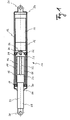
- the Fig. 1 shows a first embodiment of a linear actuator 10, wherein the actuating rod 24 at the same time the gas pressure cylinder 48 of a gas spring 24, 22 is.
- the Indian Fig. 1 shown linear actuator 10 has a substantially hollow cylindrical housing 12 in which a coupled with a gear 16 electric motor 14 is fixedly arranged.
- a threaded spindle 18 is arranged in the housing 12, which is mounted on two spaced-apart rolling bearings 34 in the interior of the housing 12 on the inner wall thereof.
- the threaded spindle 18 is a substantially hollow cylindrical component, which is arranged concentrically to the housing 12 of the linear actuator 10.
- the threaded spindle 18 thus forms a cavity 42, wherein on the cavity 42 surrounding inner wall of the threaded spindle 18, an internal thread 44 is formed.
- the linear actuator 10 has a spindle nut 20, which is located in the cavity 42 of the threaded spindle 18.
- the spindle nut 20 is provided on its outer circumference with an external thread 46, which is in engagement with the internal thread 44 of the threaded spindle 18, so that the spindle nut 20 is screwed depending on the direction of rotation of the threaded spindle 18 in the longitudinal direction of the threaded spindle 18 forward or backward.
- an actuating rod 24 is coupled, which extends through a provided with a sealing element 40 outlet opening of the housing 12 out of the same.
- the caused by the electric motor 14 rotational movement is via the gear 16 and in particular its output shaft 32 to the threaded spindle 18 transferred, which in conjunction with the spindle 42 thereof located in the same spindle nut 20 converts the rotational movement into a translational linear movement of the spindle nut 20, so that the actuating rod 24 depending on the direction of rotation of the threaded spindle 18 in the cavity 42 of the threaded spindle 18 is retracted or telescoped.
- the spindle nut 20 performs no rotational movement.
- the spindle nut 20 is due to the threaded engagement with the internal thread 44 of the threaded spindle 18 rather only forward or backward in the longitudinal direction of the threaded spindle 18 to the operating rod 24 in the housing 12 and the cavity 42 of the threaded spindle 18 to telescope or telescope.
- the linear actuator 10 In order to use the linear movement of the linear actuator 10 for opening and / or closing, for example, a tailgate of a motor vehicle, the linear actuator 10 according to the invention at its two opposite ends in each case a fastening eye 36, 38, wherein the one fastening eye 38 at the freely projecting end of the actuating rod 24 is formed, whereas the other fastening eye 36 is formed on a detachably attached to the housing 12 closure cover 54 which can be removed for revision or repair purposes of the housing 12.
- the actuating rod 24 may be under a biasing force, which tends to push the actuating rod 24 out of the cavity 42 of the threaded spindle 18.
- a biasing force could, for example On the actuating rod 24 and the coupled thereto spindle nut 20 are generated via a located in the cavity 42 helical compression spring which is supported on the one hand on the spindle nut 20 and on the other hand on the end surface 26.
- the entire length of the threaded spindle 18 is provided according to a preferred embodiment to apply said biasing force by means of a gas spring ,
- the actuating rod 24 is formed in this preferred embodiment as a gas pressure cylinder 48 of a gas spring, the piston rod 22 is fixed and concentric within the cavity 42 of the threaded spindle 18 extends, as in the in the Fig. 1 illustrated embodiment is the case.
- the piston rod 22 engages in a blind hole 28 formed in the end surface 26.
- the piston rod 22 thus forms in conjunction with the actuating rod 24 formed as a gas pressure cylinder 24, a gas spring, which due to the different large pressure effective surfaces on both sides of the (not shown here) piston within the gas cylinder 24 has the tendency to gas cylinder 24 from the cavity 42 of the threaded spindle 28 push out.
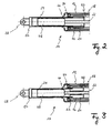
- Fig. 2 is shown provided to form the gas pressure cylinder 48 as a separate from the operating rod 24 component.
- the actuating rod 24 has a hollow cylindrical shape, but in this embodiment, the actuating rod 24 accommodates in its cavity the gas pressure cylinder 48 of a gas spring, the piston rod 22 extends fixedly and concentrically within the cavity 42 of the threaded spindle.
- the gas pressure cylinder 48 is easily accessible from the outside via a releasably attached to the free end of the actuating rod 24 closure body 50 so that the gas spring 48, 22 can be easily pulled out of the cavity of the actuating rod 24 after the closure body 50 of the actuating rod 24th was removed.
- the spindle nut 20 is integrally connected to the actuating rod 24.
- the spindle nut 20 via a threaded connection 52 according to Fig. 3 detachably connected to the actuating rod 24, so that even in the case that deviates from the Fig. 2 the gas spring or its gas pressure cylinder 48 should not be designed as a separate from the operating rod 24 component, the gas pressure cylinder 48 formed as actuating rod 24 (according to Fig. 1 ) can be easily replaced.
Landscapes
- Engineering & Computer Science (AREA)
- General Engineering & Computer Science (AREA)
- Mechanical Engineering (AREA)
- Transmission Devices (AREA)
- Connection Of Motors, Electrical Generators, Mechanical Devices, And The Like (AREA)
- Constitution Of High-Frequency Heating (AREA)
- Glass Compositions (AREA)
- Seal Device For Vehicle (AREA)
Abstract
Description
- Die vorliegende Erfindung betrifft einen von einem Elektromotor angetriebenen Linearaktuator, der die Drehbewegung des Elektromotors in eine translatorische bzw. lineare Bewegung eines Spindeltriebs umsetzt.
- Derartige Linearaktuatoren können beispielsweise im Bereich der Kraftfahrzeugtechnik zum Einsatz kommen, wo sie beispielsweise zum Öffnen und Schließen von Heckklappen, Kofferraumdeckeln, Motorhauben oder dergleichen Verwendung finden.
- Damit beim Öffnen oder Schließen beispielsweise einer Heckklappe nicht das gesamte Gewicht der Heckklappe bewegt bzw. aufgefangen werden muss, kommen üblicherweise Gewichtsausgleichs- oder Gegengewichtsysteme zum Einsatz, die das Gewicht der Heckklappe kompensieren, so dass nur noch eine geringe zusätzliche Kraft zum Öffnen der Heckklappe erforderlich ist, welche entweder von Hand oder mittels eines Betätigungsaktuators aufgebracht werden kann. Beispielsweise kommen bei von Hand betätigbaren Heckklappen als Gegengewichtsystem üblicherweise zwei Gasdruckfedern zum Einsatz, die das Gewicht der Heckklappe kompensieren.
- Um den gewünschten Gewichtsausgleich für beispielsweise eine Heckklappe zu schaffen, die von einem motorisch angetriebenen Linearaktuator betätigt wird, kann ein Gewichtsausgleichsystem zum Einsatz kommen, welches entweder in den Linearaktuator integriert oder als separate Einheit vorgesehen ist. Bei separaten Gewichtsausgleichssystemen handelt es sich häufig um gewöhnliche Gasdruckfedern, die den gewünschten Gewichtsausgleich schaffen. Bei integrierten Gewichtsausgleichssystemen handelt es sich hingegen meist um eine in den Linearaktuator integrierte Schraubendruckfeder, die für den gewünschten Gewichtsausgleich sorgt.
- Durch die Integration einer derartigen Schraubendruckfeder in den Linearaktuator erhöht sich jedoch zum einen dessen Durchmesser, da die Schraubendruckfeder konzentrisch zu den sich translatorisch bewegenden Teilen des Linearaktuators bzw. dessen Spindeltrieb angeordnet ist. Zum anderen erhöht sich durch die Integration einer derartigen Schraubendruckfeder in den Linearaktuator auch dessen Länge, da die Blocklänge der Schraubendruckfeder nicht als Hubstrecke zur Verfügung steht.
- Zwar kann dadurch, dass als Gewichtsausgleichssystem eine Gasdruckfeder in einen Linearaktuator integriert wird, dessen Länge minimiert werden, jedoch weisen derartige Linearaktuatoren, dennoch einen verhältnismäßig großen Durchmesser auf.
- Der Erfindung liegt daher die Aufgabe zugrunde, einen möglichst kompakten und kleinbauenden elektromotorisch betätigbaren Linearaktuator anzugeben.
- Diese Aufgabe wird mit einem Linearaktuator gelöst, der die Merkmale des Anspruchs 1 aufweist.
- Der erfindungsgemäße Linearaktuator weist einen Elektromotor auf, welcher innerhalb des Gehäuses des Linearaktuators befestigt ist und eine ebenfalls in dem Gehäuse angeordnete Gewindespindel antreibt. Die Gewindespindel nimmt eine Spindelmutter auf, welche die Drehbewegung der Gewindespindel in eine translatorische Linearbewegung beispielsweise zum Öffnen oder Schließen einer Heckklappe umsetzt. Um die translatorische Bewegung der Spindelmutter dabei auf eine Heckklappe übertragen zu können, ist mit der Spindelmutter eine sich aus dem Gehäuse herauserstreckende Betätigungsstange gekoppelt. An dem freien Ende der Betätigungsstange sowie an dem gegenüberliegenden Ende des Gehäuses können dabei beispielsweise Befestigungsaugen vorgesehen sein, über die der Linearaktuator an der Karosserie und an der Heckklappe angelenkt werden kann.
- Erfindungsgemäß ist es nun vorgesehen, dass die Gewindespindel ein einen Hohlraum der Gewindespindel umschreibendes Innengewinde aufweist, wohingegen die Spindelmutter ein mit dem Innengewinde der Gewindespindel in Eingriff stehendes Außengewinde aufweist, so dass die Betätigungsstange je nach Drehrichtung der Gewindespindel in den Hohlraum der Gewindespindel ein- oder austeleskopiert wird, wenn die Gewindespindel durch den Elektromotor rotatorisch angetrieben wird.
- Anders als herkömmliche Gewindespindeln weist die Gewindespindel des erfindungsgemäßen Linearaktuators also kein Außen- sondern ein Innengewinde auf. In entsprechender Weise weist die zugehörige Spindelmutter anders als zu herkömmlichen Gewindespindeln zugehörige Spindelmuttern kein Innen- sondern ein Außengewinde auf, so dass bei einer Drehung der Gewindespindel die Spindelmutter im Hohlraum der Gewindespindel zu einer Linearbewegung veranlasst wird.
- Zwar wäre es ebenfalls möglich, das im Rahmen der vorliegenden Erfindung als Gewindespindel bezeichnete Bauteil aufgrund dessen Innengewindes als lange Spindelmutter zu betrachten und dementsprechend das im Rahmen der vorliegenden Erfindung als Spindelmutter bezeichnete Bauteil aufgrund deren Außengewinde als (kurze) Gewindespindel zu betrachten; da jedoch das im Rahmen der vorliegenden Erfindung als Gewindespindel bezeichnete Bauteil mit Innengewinde durch den Elektromotor einer Drehbewegung unterworfen wird, wohingegen das im Rahmen der vorliegenden Erfindung als Spindelmutter bezeichnete Bauteil durch die Drehbewegung der Gewindespindel einer translatorischen Linearbewegung über die Länge der Gewindespindel hinweg unterworfen wird, orientiert sich die Terminologie für die in Rede stehenden Bauteile in Übereinstimmung mit herkömmlichen Spindeltrieben daran, dass es sich bei dem drehbaren Bauteil um die Gewindespindel handelt, wohingegen das sich infolge der Drehung der Gewindespindel translatorisch bewegende Bauteil die Spindelmutter ist. Bei der Gewindespindel handelt es sich somit in Übereinstimmung mit der üblicherweise verwendeten Terminologie um das längere Bauteil mit einer höheren Anzahl an Gewindegängen, wohingegen es sich bei der Spindelmutter um das kürzere Bauteil mit einer geringeren Anzahl an Gewindegängen handelt.
- Zur Betätigung des Linearaktuators wird die Gewindespindel mit Hilfe des Elektromotors und gegebenenfalls einer zwischen den Elektromotor und die Gewindespindel zwischengeschalteten Getriebeeinheit innerhalb des Gehäuses in Drehung versetzt, was infolge des Gewindeeingriffs der Spindelmutter mit der Gewindespindel dazu führt, dass die Spindelmutter zusammen mit der damit gekoppelten Betätigungsstange zu einer translatorischen Linearbewegung veranlasst wird, bei der die Betätigungsstange je nach Drehrichtung der Gewindespindel im Hohlraum derselben ein-oder austeleskopiert wird.
- Im Folgenden wird auf bevorzugte Ausführungsformen des erfindungsgemäßen Linearaktuators eingegangen, welche sich aus den Unteransprüchen, der Figurenbeschreibung sowie den Zeichnungen ergeben.
- Da es sich bei der Betätigungsstange um den Gasdruckzylinder einer Gasdruckfeder handeln kann, worauf noch genauer eingegangen wird, kann durch die erfindungsgemäße Ausbildung der Gewindespindel eine sehr kompakte Bauform erreicht werden, da innerhalb der Gewindespindel nicht nur die Betätigungsstange sondern auch geeignete Mittel angeordnet sein können, mit denen die Betätigungsstange mit einer Vorspannkraft beaufschlagt werden kann, die die Tendenz hat, ihn aus dem Hohlraum der Gewindespindel herauszudrücken. So wäre es beispielsweise möglich, eine Schraubendruckfeder innerhalb des Hohlraums der Gewindespindel anzuordnen, welche sich einerseits an einer Endfläche der Gewindespindel und andererseits an der Gewindemutter abstützt, um so die gewünschte Vorspannkraft zum Gewichtsausgleich über die Spindelmutter auf die Betätigungsstange aufbringen zu können.
- Da sich durch die Blocklänge einer derartigen Schraubendruckfeder jedoch die Gesamtlänge des erfindungsgemäßen Linearaktuators in unerwünschter Weise erhöhen würde, ist es gemäß einer bevorzugten Ausführungsform vorgesehen, die Betätigungsstange in der bereits zuvor angesprochenen Art und Weise als Gasdruckzylinder einer Gasdruckfeder auszubilden, deren Kolbenstange sich ortsfest innerhalb des Hohlraums der Gewindespindel erstreckt. Da bei dieser bevorzugten Ausführungsform innerhalb der Gewindespindel keine Spiraldruckfeder angeordnet ist, steht somit die gesamte Länge der Gewindespindel für die gewünschte Linearbewegung der Spindelmutter bzw. der mit dieser gekoppelten Betätigungsstange zur Verfügung, wodurch sich die Gesamtlänge des Linearaktuators reduzieren lässt.
- Da eine Gasdruckfeder in aller Regel lediglich für ca. 30.000 Betätigungszyklen ausgelegt ist, eine Heckklappe jedoch zumindest ca. 50.000 Betätigungszyklen schadfrei überstehen sollte, besteht ein Bedarf danach, den erfindungsgemäßen Linearaktuator derart auszugestalten, dass dessen Gasdruckfeder bestehend aus Gasdruckzylinder und Kolbenstange für Wartungs- oder Reparaturzwecke leicht zugänglich und vorzugsweise austauschbar ist.
- Dementsprechend kann die Betätigungsstange gemäß einer Ausführungsform eine hohlzylindrische Gestalt aufweisen, wobei die Betätigungsstange in ihrem Hohlraum den Gasdruckzylinder einer Gasdruckfeder aufnimmt, deren Kolbenstange sich wiederum ortsfest innerhalb des Hohlraums der Gewindespindel erstreckt, wie dies bereits zuvor beschrieben wurde. Die Betätigungsstange des Linearaktuators dient somit gewissermaßen als Gehäuse zur Aufnahme der Gasdruckfeder bzw. deren Gasdruckzylinder, so dass die Gasdruckfeder bei Bedarf leicht ausgetauscht werden kann.
- Um einen derartigen Austausch weiter zu vereinfachen, kann der Hohlraum der Betätigungsstange am außerhalb des Gehäuses des Linearaktuators befindlichen Ende der Betätigungsstange durch einen lösbar, vorzugsweise durch einen über eine Gewindeverbindung an der Betätigungsstange angebrachten Verschlusskörper begrenzt sein. Um die Gasdruckfeder austauschen zu können, braucht somit lediglich der genannte Verschlusskörper, bei dem es sich beispielsweise um eine Art Verschlusskappe handeln kann, entfernt bzw. von der Betätigungsstange abgeschraubt werden, so dass der Hohlraum der Betätigungsstange von außen frei zugänglich ist und die zu ersetzende Gasdruckfeder aus dem Hohlraum der Betätigungsstange herausgezogen und eine neue Gasdruckfeder eingeschoben werden kann.
- Wie bereits zuvor ausgeführt wurde, kann die hohlzylindrische Gestalt der Gewindespindel bzw. deren Hohlraum an einem Ende durch eine Endfläche begrenzt sein, an der sich die Kolbenstange der Gasdruckfeder abstützt. Zur Aufnahme der Kolbenstange kann hierzu in der Endfläche eine Sacklochausnehmung ausgebildet sein, so dass die Kolbenstange seitlich nicht ausweichen kann. Auf der der Kolbenstange gegenüberliegenden Seite der Endfläche kann diese ferner eine geeignete Eingriffsöffnung beispielsweise ebenfalls in Form einer Sacklochausnehmung aufweisen, in die die Antriebswelle des Elektromotors oder im Falle eines zwischen den Elektromotor und die Gewindespindel zwischengeschalteten Getriebeeinheit deren Abtriebswelle zu Zwecken des Antriebs der Gewindespindel formschlüssig eingreifen kann.
- Um unerwünschte Reibungserscheinungen infolge der Drehung der Gewindespindel innerhalb des Gehäuses zu vermeiden, kann die Gewindespindel ferner drehbar in dem Gehäuse über zumindest ein Wälzlager gelagert sein, wodurch gleichzeitig sichergestellt wird, dass die Gewindespindel sich in dem Gehäuse nicht verkantet.
- Zwar wäre es grundsätzlich möglich, die Betätigungsstange über ihre gesamte Länge hinweg mit einem Außengewinde auszustatten, welches je nach Betätigungsstellung des Linearaktuators mehr oder weniger weit mit dem Innengewinde der Gewindespindel in Eingriff steht, so dass auf eine definiert abgegrenzte Spindelmutter am im innerhalb des Gehäuses befindlichen Endes der Betätigungsstange verzichtet werden könnte. Allerdings erweist sich die Schmutzabdichtung des Gehäuses des Linearaktautors gegenüber der Betätigungsstange im Falle eines sich über deren gesamte Länge hinweg erstreckenden Außengewindes als problematisch, weshalb es gemäß einer bevorzugten Ausführungsform vorgesehen ist, dass die Betätigungsstange einen glatten umfangsseitigen Schaft aufweist, an deren im Inneren des Gehäuses befindlichen Ende die Spindelmutter ausgebildet ist. Die Spindelmutter und die Betätigungsstange können dabei einstückig miteinander verbunden sein, indem die Betätigungsstange mit der daran angeformten Spindelmutter aus einem einzigen Werkstück herausgearbeitet wird.
- Da dieses Herausarbeiten der Spindelmutter und des Schafts der Betätigungsstange aus einem einzigen Werkstück beispielsweise durch Fräsen sehr arbeits- und kostenintensiv ist, kann die Spindelmutter gemäß einer weiteren Ausführungsform lösbar und vorzugsweise über eine Gewindeverbindung mit der Betätigungsstange verbunden sein. Die Spindelmutter und der Schaft der Betätigungsstange können somit separat hergestellt werden und durch eine geeignete Verbindungstechnik wie beispielsweise durch Schrauben miteinander verbunden werden.
- Um die Reibung während des Betriebs des erfindungsgemäßen Linearaktuators weiter zu reduzieren, kann die Spindelmutter in Verbindung mit der Gewindespindel als Kugelgewindetrieb ausgebildet sein. Da die Spindelmutter und die Gewindespindel somit lediglich über eine Vielzahl von Kugeln miteinander in Berührung stehen, reduziert sich die Reibung zwischen der Spindelmutter und der Gewindespindel, wodurch weniger Kraft von dem Elektromotor zur Betätigung des Linearaktuators aufgebracht werden muss.
- Gemäß einer bevorzugten Ausführungsform kann die Spindelmutter in Verbindung mit der Gewindespindel als Freilaufkugelgewindetrieb (engl.: free wheeling ball screw) ausgebildet sein. Ein derartiger Freilaufkugelgewindetrieb zeichnet sich dadurch aus, dass die Kugeln in ringförmigen Rillen in der Spindelmutter aufgenommen und von einem Käfig zwischen der Spindelmutter und der Gewindespindel aufgenommen werden. Wenn der Käfig der Spindelmutter am Ende der Gewindespindel eine Begrenzung erreicht, hört die Linearbewegung der Spindelmutter auf, da dann die in der Spindelmutter ringförmig umlaufenden Rillen dafür sorgen, dass es zu keiner Vorschubbewegung mehr kommt. Obwohl sich die Gewindespindel weiter dreht, wird somit kein weiterer Druck auf die Begrenzung der Gewindespindel ausgeübt. Diese Ausführungsform erweist sich dabei dahingehend als vorteilhaft, dass durch die Ausbildung der Spindelmutter und der Gewindespindel als Freilaufkugelgewindetrieb im Falle eines Ausfalls der Steuerung des Elektromotors trotz anhaltenden Antriebs des Linearaktuators durch die Spindelmutter keine weitere Linearbewegung mehr hervorgerufen wird, wodurch die Gefahr einer Überhitzung des Elektromotors verringert werden kann.
- Im Folgenden wird nun die Erfindung rein exemplarisch anhand unterschiedlicher, beispielhafter Ausführungsformen unter Bezugnahme auf die beigefügten Zeichnungen beschrieben, wobei:
- Fig. 1
- eine schematische Darstellung einer ersten Ausführungsform eines erfindungsgemäßen Linearaktuators zeigt;
- Fig. 2
- eine schematische Darstellung einer zweite Ausführungsform eines erfindungsgemäßen Linearaktuators im Bereich der Be- tätigungsstange zeigt; und
- Fig. 3
- eine schematische Darstellung einer dritten Ausführungsform eines erfindungsgemäßen Linearaktuators im Bereich der Be- tätigungsstange zeigt.
- Die
Fig. 1 zeigt eine erste Ausführungsform eines Linearaktuators 10, bei der die Betätigungsstange 24 gleichzeitig der Gasdruckzylinder 48 einer Gasdruckfeder 24, 22 ist. Der in derFig. 1 dargestellte Linearaktuator 10 weist ein im Wesentlichen hohlzylindrisches Gehäuse 12 auf, in dem ein mit einem Getriebe 16 gekoppelter Elektromotor 14 fest angeordnet ist. - Darüber hinaus ist in dem Gehäuse 12 eine Gewindespindel 18 angeordnet, welche über zwei beabstandet zueinander angeordnete Wälzlager 34 im Inneren des Gehäuses 12 an dessen Innenwandung gelagert ist. Bei der Gewindespindel 18 handelt es sich um ein im Wesentlichen hohlzylindrisches Bauteil, welches konzentrisch zu dem Gehäuse 12 des Linearaktuators 10 angeordnet ist. Die Gewindespindel 18 bildet somit einen Hohlraum 42 aus, wobei an der den Hohlraum 42 umgebenden Innenwandung der Gewindespindel 18 ein Innengewinde 44 ausgebildet ist.
- Auf der dem Getriebe 16 zugewandten Seite ist der Hohlraum 42 der Gewindespindel 18 durch eine Endfläche 26 in Form einer Wand begrenzt. Diese Wand 26 weist dabei auf der dem Getriebe 16 zugewandten Seite eine Eingriffsausnehmung in Form einer Sacklochausnehmung 30 auf, in die die Abtriebswelle 32 des Getriebes 16 formschlüssig eingreift, um die Gewindespindel 18 rotatorisch antreiben zu können.
- Darüber hinaus weist der Linearaktuator 10 eine Spindelmutter 20 auf, welche sich in dem Hohlraum 42 der Gewindespindel 18 befindet. Die Spindelmutter 20 ist an ihrem Außenumfang mit einem Außengewinde 46 versehen, welches mit dem Innengewinde 44 der Gewindespindel 18 in Eingriff steht, so dass die Spindelmutter 20 je nach Drehrichtung der Gewindespindel 18 in Längsrichtung der Gewindespindel 18 nach vorne oder nach hinten geschraubt wird.
- Mit der Spindelmutter 20 ist eine Betätigungsstange 24 gekoppelt, welche sich durch eine mit einem Dichtelement 40 versehene Austrittsöffnung des Gehäuses 12 aus demselben heraus erstreckt.
- Die von dem Elektromotor 14 hervorgerufene Drehbewegung wird über das Getriebe 16 und insbesondere dessen Abtriebswelle 32 auf die Gewindespindel 18 übertragen, welche in Verbindung mit der im Hohlraum 42 derselben befindlichen Spindelmutter 20 die Drehbewegung in eine translatorische Linearbewegung der Spindelmutter 20 umsetzt, so dass die Betätigungsstange 24 je nach Drehrichtung der Gewindespindel 18 in den Hohlraum 42 der Gewindespindel 18 ein- oder austeleskopiert wird.
- Bei dieser Betätigung des Linearaktuators 10 wird lediglich die Gewindespindel 18 dazu veranlasst, eine Drehbewegung auszuführen, wohingegen die Spindelmutter 20 keine Drehbewegung ausführt. Die Spindelmutter 20 wird infolge des Gewindeeingriffs mit dem Innengewinde 44 der Gewindespindel 18 vielmehr lediglich in Längsrichtung der Gewindespindel 18 vor- oder zurückbewegt, um die Betätigungsstange 24 in das Gehäuse 12 bzw. den Hohlraum 42 der Gewindespindel 18 ein- oder austeleskopieren zu können.
- Um die Linearbewegung des Linearaktuators 10 zum Öffnen und/oder Schließen beispielsweise einer Heckklappe eines Kraftfahrzeugs verwenden zu können, weist der erfindungsgemäße Linearaktuator 10 an seinen zwei gegenüberliegenden Enden jeweils ein Befestigungsauge 36, 38 auf, wobei das eine Befestigungsauge 38 am frei auskragenden Ende der Betätigungsstange 24 ausgebildet ist, wohingegen das andere Befestigungsauge 36 an einem lösbar an dem Gehäuse 12 angebrachten Verschlussdeckel 54 ausgebildet ist, welcher zu Revisions- oder Reparaturzwecken von dem Gehäuse 12 entfernt werden kann.
- Damit die zum Öffnen beispielsweise einer Heckklappe benötigte Kraft nicht ausschließlich von dem Elektromotor 14 aufgebracht werden muss, kann die Betätigungsstange 24 unter einer Vorspannkraft stehen, die die Tendenz hat, die Betätigungsstange 24 aus dem Hohlraum 42 der Gewindespindel 18 herauszudrücken. Eine derartige Vorspannkraft könnte beispielsweise auf die Betätigungsstange 24 bzw. die damit gekoppelte Spindelmutter 20 über eine in dem Hohlraum 42 befindliche Schraubendruckfeder erzeugt werden, welche sich einerseits an der Spindelmutter 20 und andererseits an der Endfläche 26 abstützt.
- Da jedoch in diesem Falle aufgrund der Blocklänge einer derartig angeordneten Schraubendruckfeder nicht die gesamte Länge der Gewindespindel 18 als Hubstrecke für die Spindelmutter 20 und die Betätigungsstange 24 zur Verfügung stehen würde, ist es gemäß einer bevorzugten Ausführungsform vorgesehen, die genannte Vorspannkraft mit Hilfe einer Gasdruckfeder aufzubringen. Dementsprechend ist die Betätigungsstange 24 bei dieser bevorzugten Ausführungsform als Gasdruckzylinder 48 einer Gasdruckfeder ausgebildet, deren Kolbenstange 22 sich ortsfest und konzentrisch innerhalb des Hohlraums 42 der Gewindespindel 18 erstreckt, wie dies bei der in der
Fig. 1 dargestellten Ausführungsform der Fall ist. An dem der Spindelmutter 20 gegenüberliegenden Ende der Kolbenstange 22 greift die Kolbenstange 22 dabei in eine in der Endfläche 26 ausgebildete Sacklochausnehmung 28 ein. Die Kolbenstange 22 bildet somit in Verbindung mit der als Gasdruckzylinder 48 ausgebildeten Betätigungsstange 24 eine Gasdruckfeder, welche aufgrund der unterschiedlich großen druckwirksamen Flächen beiderseits des (hier nicht dargestellten) Kolbens innerhalb des Gasdruckzylinders 24 die Tendenz hat, den Gasdruckzylinder 24 aus dem Hohlraum 42 der Gewindespindel 28 herauszudrücken. - Um die Gasdruckfeder bestehend aus Gasdruckzylinder 48 und Kolbenstange 22 möglichst schnell und einfach austauschen zu können, ist es gemäß einer anderen Ausführungsform, welche in der
Fig. 2 dargestellt ist, vorgesehen, den Gasdruckzylinder 48 als ein von der Betätigungsstange 24 separates Bauteil auszubilden. Wie derFig. 2 entnommen werden kann, weist auch bei dieser Ausführungsform die Betätigungsstange 24 eine hohlzylindrische Gestalt auf, wobei bei dieser Ausführungsform jedoch die Betätigungsstange 24 in ihrem Hohlraum den Gasdruckzylinder 48 einer Gasdruckfeder aufnimmt, deren Kolbenstange 22 sich ortsfest und konzentrisch innerhalb des Hohlraums 42 der Gewindespindel erstreckt. Der Gasdruckzylinder 48 ist dabei von außen her über einen am freien Ende der Betätigungsstange 24 lösbar angebrachten Verschlusskörper 50 leicht zugänglich, so dass die Gasdruckfeder 48, 22 ohne weiteres aus dem Hohlraum der Betätigungsstange 24 herausgezogen werden kann, nachdem der Verschlusskörper 50 von der Betätigungsstange 24 entfernt wurde. - Bei den beiden in den
Fig. 1 und2 dargestellten Ausführungsformen ist die Spindelmutter 20 einstückig mit der Betätigungsstange 24 verbunden. In produktionstechnischer Hinsicht kann es sich jedoch als vorteilhaft erweisen, die Spindelmutter 22 als separates Bauteil zu fertigen und erst nachträglich mit der Betätigungsstange 24 zu verbinden. So kann beispielsweise die Spindelmutter 20 über eine Gewindeverbindung 52 gemäßFig. 3 lösbar mit der Betätigungsstange 24 verbunden sein, so dass auch im Falle, dass abweichend von derFig. 2 die Gasdruckfeder bzw. deren Gasdruckzylinder 48 nicht als ein von der Betätigungsstange 24 separates Bauteil ausgeführt sein sollte, die als Gasdruckzylinder 48 ausgebildete Betätigungsstange 24 (gemäßFig. 1 ) leicht ausgetauscht werden kann. -
- 10
- Linearaktuator
- 12
- Gehäuse
- 14
- Elektromotor
- 16
- Getriebe
- 18
- Gewindespindel
- 20
- Spindelmutter
- 22
- Kolbenstange
- 24
- Betätigungsstange
- 26
- Endfläche/Wand
- 28
- Sacklochausnehmung
- 30
- Sacklochausnehmung
- 32
- Antriebswelle
- 34
- Wälzlager
- 36
- Befestigungsauge
- 38
- Befestigungsauge
- 40
- Dichtung
- 42
- Hohlraum von 18
- 44
- Innengewinde
- 46
- Außengewinde
- 48
- Gasdruckzylinder
- 50
- Verschlusskörper
- 52
- Gewindeverbindung
- 54
- Verschlussdeckel
Claims (10)
- Linearaktuator (10) umfassend:- ein Gehäuse (12);- einen in dem Gehäuse (12) befestigten Elektromotor (14);- eine in dem Gehäuse (12) angeordnete, von dem Elektromotor (14) drehbar angetriebene Gewindespindel (18);- eine von der Gewindespindel (18) aufgenommene Spindelmutter (20), die die Drehbewegung der Gewindespindel (18) in eine translatorische Bewegung umsetzt; und- eine sich aus dem Gehäuse (12) herauserstreckende Betätigungsstange (24), die mit der Spindelmutter (20) gekoppelt ist;dadurch gekennzeichnet,dass
die Gewindespindel (18) ein einen Hohlraum (42) der Gewindespindel (18) umschreibendes Innengewinde (44) und die Spindelmutter (20) ein mit dem Innengewinde (44) der Gewindespindel (18) in Eingriff stehendes Außengewinde (46) aufweist, so dass die Betätigungsstange (24) je nach Drehrichtung der Gewindespindel (18) in den Hohlraum (42) der Gewindespindel (18) ein- oder austeleskopierbar ist. - Linearaktuator nach Anspruch 1,
dadurch gekennzeichnet,dass
die Betätigungsstange (24) unter einer Vorspannkraft steht, die Tendenz hat, sie aus dem Hohlraum (42) der Gewindespindel (18) herauszudrücken. - Linearaktuator nach Anspruch 1 oder 2,
dadurch gekennzeichnet,dass
die Betätigungsstange (24) der Zylinder (48) einer Gasdruckfeder ist, deren Kolbenstange (22) sich ortfest innerhalb des Hohlraums (42) der Gewindespindel (18) erstreckt. - Linearaktuator nach Anspruch 1 oder 2,
dadurch gekennzeichnet, dass
die Betätigungsstange (24) eine hohlzylindrische Gestalt aufweist, wobei die Betätigungsstange (24) in ihrem Hohlraum den Zylinder (48) einer Gasdruckfeder aufnimmt, deren Kolbenstange (22) sich ortfest innerhalb des Hohlraums (42) der Gewindespindel (18) erstreckt. - Linearaktuator nach Anspruch 4,
dadurch gekennzeichnet, dass
der Hohlraum der Betätigungsstange (24) am außerhalb des Gehäuses (12) befindlichen Ende der Betätigungsstange (24) durch einen lösbar, insbesondere durch eine über eine Gewindeverbindung an der Betätigungsstange (24) angebrachten Verschlussköper (50) begrenzt ist. - Linearaktuator nach zumindest einem der Ansprüche 3 bis 5,
dadurch gekennzeichnet, dass
die Gewindespindel (18) eine hohlzylindrische Gestalt aufweist, deren Hohlraum (42) an einem Ende durch eine Wand (26) begrenzt ist, an der sich die Kolbenstange (22) abstützt. - Linearaktuator nach zumindest einem der vorstehenden Ansprüche,
dadurch gekennzeichnet, dass
die Gewindespindel (18) drehbar in dem Gehäuse (12) gelagert ist. - Linearaktuator nach zumindest einem der vorstehenden Ansprüche,
dadurch gekennzeichnet, dass
die Spindelmutter (20) lösbar, insbesondere über eine Gewindeverbindung (52) mit der Betätigungsstange (24) verbunden ist. - Linearaktuator nach zumindest einem der vorstehenden Ansprüche,
dadurch gekennzeichnet, dass
die Spindelmutter (20) einstückig mit der Betätigungsstange (24), insbesondere an deren im Inneren des Gehäuses (12) befindlichen Ende ausgebildet ist. - Linearaktuator nach zumindest einem der vorstehenden Ansprüche,
dadurch gekennzeichnet, dass
die Spindelmutter (20) in Verbindung mit der Gewindespindel (18) als Kugelgewindetrieb und insbesondere als Freilaufkugelgewindetrieb ausgebildet ist.
Priority Applications (1)
| Application Number | Priority Date | Filing Date | Title |
|---|---|---|---|
| US12/220,115 US20090044645A1 (en) | 2007-08-14 | 2008-07-22 | Motor driven linear actuator |
Applications Claiming Priority (1)
| Application Number | Priority Date | Filing Date | Title |
|---|---|---|---|
| GBGB0715754.8A GB0715754D0 (en) | 2007-08-14 | 2007-08-14 | Powered closure device |
Publications (2)
| Publication Number | Publication Date |
|---|---|
| EP2025852A1 true EP2025852A1 (de) | 2009-02-18 |
| EP2025852B1 EP2025852B1 (de) | 2011-08-31 |
Family
ID=38543485
Family Applications (1)
| Application Number | Title | Priority Date | Filing Date |
|---|---|---|---|
| EP07018504A Not-in-force EP2025852B1 (de) | 2007-08-14 | 2007-09-20 | Motorisch angetriebener Linearaktuator |
Country Status (4)
| Country | Link |
|---|---|
| US (1) | US20090044645A1 (de) |
| EP (1) | EP2025852B1 (de) |
| AT (1) | ATE522693T1 (de) |
| GB (1) | GB0715754D0 (de) |
Cited By (3)
| Publication number | Priority date | Publication date | Assignee | Title |
|---|---|---|---|---|
| DE102011116559A1 (de) * | 2011-10-21 | 2013-04-25 | BROSE SCHLIEßSYSTEME GMBH & CO. KG | Verfahren zur Herstellung eines Spindelantriebs für ein Verstellelement eines Kraftfahrzeugs |
| FR3010748A1 (fr) * | 2013-09-13 | 2015-03-20 | Messier Bugatti Dowty | Actionneur telescopique. |
| WO2023062090A3 (de) * | 2021-10-12 | 2023-06-08 | Inventus Engineering Gmbh | Türkomponente und verfahren |
Families Citing this family (20)
| Publication number | Priority date | Publication date | Assignee | Title |
|---|---|---|---|---|
| DE102008028335B3 (de) * | 2008-06-13 | 2010-05-06 | Limoss Gmbh & Co. Kg | Linearer Stellantieb für Sitz- und/oder Liegemöbel |
| SE533597C2 (sv) * | 2009-02-02 | 2010-11-02 | Reac Ab | Ställdon |
| DE102009027418A1 (de) * | 2009-07-02 | 2011-01-05 | Zf Friedrichshafen Ag | Elektromechanische Linearstelleinheit |
| WO2011057640A1 (en) * | 2009-11-12 | 2011-05-19 | Lego A/S | A toy building set with an overload-safe linear actuator |
| US8875442B2 (en) * | 2010-03-16 | 2014-11-04 | Strattec Power Access Llc | Method and apparatus of active dampening a powered closure system |
| EP2543808B1 (de) * | 2011-07-05 | 2020-03-04 | U-Shin Deutschland Zugangssysteme GmbH | Aktuatorvorrichtung zum automatischen Betätigen der Fahrzeugtür eines Kraftfahrzeugs |
| FR2981707B1 (fr) | 2011-10-24 | 2013-12-20 | Astrium Sas | Verin electrique comprenant des moyens de limitation d'effort et lanceur spatial comprenant une tuyere supportee par un tel verin |
| CA2892148C (en) * | 2012-11-30 | 2020-01-14 | D-Box Technologies Inc. | Linear actuator for motion simulator |
| ITMI20131553A1 (it) * | 2013-09-20 | 2015-03-21 | Sestese Off Mec | Testa di reggiatura compatta. |
| JP6173293B2 (ja) * | 2014-12-02 | 2017-08-02 | 株式会社ハイレックスコーポレーション | 伸縮駆動装置および開閉体開閉装置 |
| DE102015204068A1 (de) | 2015-03-06 | 2016-09-08 | Schaeffler Technologies AG & Co. KG | Linearer Stellantrieb und Verfahren zur Montage eines Stellantriebs |
| US10100568B2 (en) * | 2015-08-12 | 2018-10-16 | Magna Closures Inc. | Electromechanical strut with lateral support feature |
| DE102017204914A1 (de) * | 2016-04-07 | 2017-10-12 | Magna Closures Inc. | Kraft-Schwenktür-Betätigungsglied mit gelenkigem Verbindungsmechanismus |
| US10355554B2 (en) * | 2017-04-03 | 2019-07-16 | Caterpillar Inc. | Electric powered linear actuator |
| PL3710394T3 (pl) * | 2017-12-13 | 2024-06-10 | Joy Global Underground Mining Llc | Podpora narzędzia wiertniczego i wkręcającego |
| DE102020209947A1 (de) * | 2020-08-06 | 2022-02-10 | Robert Bosch Gesellschaft mit beschränkter Haftung | Antriebseinrichtung für eine elektromechanische Bremseinrichtung, Bremseinrichtung |
| AU2022228085A1 (en) | 2021-09-07 | 2023-03-23 | Joy Global Underground Mining Llc | Support for drilling and bolting tool |
| CN222009929U (zh) * | 2024-02-20 | 2024-11-15 | 常州市惟恩科技开发有限公司 | 电动尾门撑杆 |
| CN222009928U (zh) * | 2024-02-20 | 2024-11-15 | 常州市惟恩科技开发有限公司 | 汽车电动尾门撑杆 |
| DE102024132075A1 (de) | 2024-11-05 | 2026-05-07 | Stabilus Gmbh | Stellvorrichtung |
Citations (4)
| Publication number | Priority date | Publication date | Assignee | Title |
|---|---|---|---|---|
| US5944376A (en) * | 1997-06-11 | 1999-08-31 | Valeo, Inc. | Method and apparatus for load compensating doors and hatches |
| DE102004044306A1 (de) * | 2004-09-10 | 2006-03-16 | Brose Schließsysteme GmbH & Co.KG | Antriebsanrodnung zur Betätigung der Klappe eines Kraftfahrzeugs |
| DE202005016953U1 (de) * | 2005-10-27 | 2007-03-08 | BROSE SCHLIEßSYSTEME GMBH & CO. KG | Antriebsanordnung zur motorischen Betätigung eines Funktionselements in einem Kraftfahrzeug |
| EP1767439A2 (de) * | 2005-06-27 | 2007-03-28 | Stabilus GmbH | Antriebseinrichtung |
Family Cites Families (21)
| Publication number | Priority date | Publication date | Assignee | Title |
|---|---|---|---|---|
| FR951949A (fr) * | 1947-08-09 | 1949-11-07 | Auxiliaire Ind L | Vérin à vis, à moteur réversible, et sortie de secours de la tige |
| US2590745A (en) * | 1949-10-29 | 1952-03-25 | Wuensch Guido | Screw and nut mechanism |
| US3159758A (en) * | 1962-03-27 | 1964-12-01 | Bendix Corp | Rotary motor driven nonjamming linear actuator |
| US3724004A (en) * | 1971-06-01 | 1973-04-03 | Stiegelmeyer & Co Gmbh | Adjustable bed |
| US4179944A (en) * | 1977-06-27 | 1979-12-25 | United Technologies Corporation | Fail safe redundant actuator |
| DE3221792C2 (de) * | 1982-06-09 | 1984-07-05 | Philips Patentverwaltung Gmbh, 2000 Hamburg | Aktuatorschrittmotor |
| US4569503A (en) * | 1985-02-26 | 1986-02-11 | Gray Tool Company | Valve with remote and manual actuation means |
| JPS62231856A (ja) * | 1986-03-31 | 1987-10-12 | Aisin Seiki Co Ltd | 回動及び直線方向往復動装置 |
| US4876906A (en) * | 1986-11-20 | 1989-10-31 | Sundstrand Corporation | Non-jamming actuator system |
| EP0896855B1 (de) * | 1993-10-12 | 2003-02-26 | SMC Kabushiki Kaisha | Linearantrieb |
| US7615893B2 (en) * | 2000-05-11 | 2009-11-10 | Cameron International Corporation | Electric control and supply system |
| WO2001089981A1 (en) * | 2000-05-22 | 2001-11-29 | Ideassociates (Iom) Limited | Telescopically moving structure |
| US6540266B2 (en) * | 2000-06-19 | 2003-04-01 | Macdonald-Miller Inc. | Spin forming a tubular workpiece to form a radial flange on a tubular flange and a thick rim on the radial flange |
| DE60301150T2 (de) * | 2002-02-01 | 2006-01-05 | Vetco Gray Controls Ltd., Nailsea | Linearantrieb |
| US7207278B2 (en) * | 2003-07-03 | 2007-04-24 | Wright Line, Llc | Electrically-driven computer monitor lift and storage assembly |
| US7152496B2 (en) * | 2003-11-14 | 2006-12-26 | Jaegar Industrial Co. Ltd. | Screw nut assembly of linear actuation device |
| US7298108B2 (en) * | 2004-11-29 | 2007-11-20 | Smc Kabushiki Kaisha | Control system for electric actuator |
| US7267044B1 (en) * | 2005-03-01 | 2007-09-11 | John Hamilton Klinger | Compact actuator with large thrust |
| US20090079217A1 (en) * | 2007-09-26 | 2009-03-26 | Nikesh Bakshi | Powered Tailgate Ramp |
| GB0813906D0 (en) * | 2008-07-30 | 2008-09-03 | Goodrich Actuation Systems Ltd | Actuator |
| US8827205B2 (en) * | 2009-05-08 | 2014-09-09 | Spectrum Aeronautical, Llc | Pneumatic blow-down actuator |
-
2007
- 2007-08-14 GB GBGB0715754.8A patent/GB0715754D0/en not_active Ceased
- 2007-09-20 AT AT07018504T patent/ATE522693T1/de active
- 2007-09-20 EP EP07018504A patent/EP2025852B1/de not_active Not-in-force
-
2008
- 2008-07-22 US US12/220,115 patent/US20090044645A1/en not_active Abandoned
Patent Citations (4)
| Publication number | Priority date | Publication date | Assignee | Title |
|---|---|---|---|---|
| US5944376A (en) * | 1997-06-11 | 1999-08-31 | Valeo, Inc. | Method and apparatus for load compensating doors and hatches |
| DE102004044306A1 (de) * | 2004-09-10 | 2006-03-16 | Brose Schließsysteme GmbH & Co.KG | Antriebsanrodnung zur Betätigung der Klappe eines Kraftfahrzeugs |
| EP1767439A2 (de) * | 2005-06-27 | 2007-03-28 | Stabilus GmbH | Antriebseinrichtung |
| DE202005016953U1 (de) * | 2005-10-27 | 2007-03-08 | BROSE SCHLIEßSYSTEME GMBH & CO. KG | Antriebsanordnung zur motorischen Betätigung eines Funktionselements in einem Kraftfahrzeug |
Cited By (6)
| Publication number | Priority date | Publication date | Assignee | Title |
|---|---|---|---|---|
| DE102011116559A1 (de) * | 2011-10-21 | 2013-04-25 | BROSE SCHLIEßSYSTEME GMBH & CO. KG | Verfahren zur Herstellung eines Spindelantriebs für ein Verstellelement eines Kraftfahrzeugs |
| DE102011116559B4 (de) | 2011-10-21 | 2018-03-08 | BROSE SCHLIEßSYSTEME GMBH & CO. KG | Verfahren zur Herstellung eines Spindelantriebs für ein Verstellelement eines Kraftfahrzeugs |
| FR3010748A1 (fr) * | 2013-09-13 | 2015-03-20 | Messier Bugatti Dowty | Actionneur telescopique. |
| EP2891825A3 (de) * | 2013-09-13 | 2016-03-23 | Messier-Bugatti-Dowty | Teleskopstellglied |
| US9651066B2 (en) | 2013-09-13 | 2017-05-16 | Messier-Bugatti-Dowty | Telescopic actuator |
| WO2023062090A3 (de) * | 2021-10-12 | 2023-06-08 | Inventus Engineering Gmbh | Türkomponente und verfahren |
Also Published As
| Publication number | Publication date |
|---|---|
| US20090044645A1 (en) | 2009-02-19 |
| GB0715754D0 (en) | 2007-09-19 |
| ATE522693T1 (de) | 2011-09-15 |
| EP2025852B1 (de) | 2011-08-31 |
Similar Documents
| Publication | Publication Date | Title |
|---|---|---|
| EP2025852B1 (de) | Motorisch angetriebener Linearaktuator | |
| EP2069655B1 (de) | Kombinierte fahrzeugbremse mit elektromechanisch betätigbarer feststellbremse und getriebe zur umsetzung einer rotationsbewegung in eine translationsbewegung | |
| DE102004061622B4 (de) | Türantrieb | |
| DE102016124117B4 (de) | Türkomponente mit einem steuerbaren Drehdämpfer | |
| EP0666399B1 (de) | Antriebsvorrichtung für ein zwischen Endstellungen verstellbares Teil eines Fahrzeuges | |
| WO2015176866A1 (de) | Lenkgetriebe | |
| DE202014103629U1 (de) | Schieber | |
| EP1298274B1 (de) | Flügeltürantrieb mit Federschliessung | |
| EP2334946B1 (de) | Pneumatischer bremszylinder | |
| DE102013217161B4 (de) | Lineareinheit | |
| DE19948265C2 (de) | Linearstellglied | |
| EP1835110B1 (de) | Türbetätigungsvorrichtung, insbesondere für eine Drehtür | |
| EP2891824B1 (de) | Schieber | |
| EP0618025A1 (de) | Einpressaggregat | |
| WO2011012634A1 (de) | Wankstabilisator | |
| DE102009009395A1 (de) | Spindelstellantrieb zur Axialverlagerung einer nicht rotierenden Spindel | |
| DE102009057330A1 (de) | Elektromechanische Bremse für ein Kraftfahrzeug | |
| DE102004049796B4 (de) | Linearantrieb | |
| DE102009036350A1 (de) | Antriebsvorrichtung | |
| EP1247995A1 (de) | Linearwegschieber | |
| EP4431774A1 (de) | Stellantrieb für eine armatur | |
| EP3971448B1 (de) | Kugelgewindetrieb und spindelmutter hierfür | |
| EP1835111B1 (de) | Türbetätigungsvorrichtung, insbesondere für eine Drehtür | |
| DE10252046B4 (de) | Antrieb für eine Spritzgiessmaschine | |
| DE102004026269A1 (de) | Schneckenanordnung und damit ausgestattetes Schneckengetriebe |
Legal Events
| Date | Code | Title | Description |
|---|---|---|---|
| PUAI | Public reference made under article 153(3) epc to a published international application that has entered the european phase |
Free format text: ORIGINAL CODE: 0009012 |
|
| 17P | Request for examination filed |
Effective date: 20080123 |
|
| AK | Designated contracting states |
Kind code of ref document: A1 Designated state(s): AT BE BG CH CY CZ DE DK EE ES FI FR GB GR HU IE IS IT LI LT LU LV MC MT NL PL PT RO SE SI SK TR |
|
| AX | Request for extension of the european patent |
Extension state: AL BA HR MK RS |
|
| AKX | Designation fees paid |
Designated state(s): AT BE BG CH CY CZ DE DK EE ES FI FR GB GR HU IE IS IT LI LT LU LV MC MT NL PL PT RO SE SI SK TR |
|
| 17Q | First examination report despatched |
Effective date: 20100212 |
|
| GRAP | Despatch of communication of intention to grant a patent |
Free format text: ORIGINAL CODE: EPIDOSNIGR1 |
|
| GRAS | Grant fee paid |
Free format text: ORIGINAL CODE: EPIDOSNIGR3 |
|
| GRAA | (expected) grant |
Free format text: ORIGINAL CODE: 0009210 |
|
| AK | Designated contracting states |
Kind code of ref document: B1 Designated state(s): AT BE BG CH CY CZ DE DK EE ES FI FR GB GR HU IE IS IT LI LT LU LV MC MT NL PL PT RO SE SI SK TR |
|
| REG | Reference to a national code |
Ref country code: GB Ref legal event code: FG4D Free format text: NOT ENGLISH Ref country code: CH Ref legal event code: EP |
|
| REG | Reference to a national code |
Ref country code: IE Ref legal event code: FG4D Free format text: LANGUAGE OF EP DOCUMENT: GERMAN |
|
| REG | Reference to a national code |
Ref country code: DE Ref legal event code: R096 Ref document number: 502007008016 Country of ref document: DE Effective date: 20111027 |
|
| REG | Reference to a national code |
Ref country code: NL Ref legal event code: VDEP Effective date: 20110831 |
|
| LTIE | Lt: invalidation of european patent or patent extension |
Effective date: 20110831 |
|
| PG25 | Lapsed in a contracting state [announced via postgrant information from national office to epo] |
Ref country code: SE Free format text: LAPSE BECAUSE OF FAILURE TO SUBMIT A TRANSLATION OF THE DESCRIPTION OR TO PAY THE FEE WITHIN THE PRESCRIBED TIME-LIMIT Effective date: 20110831 Ref country code: IS Free format text: LAPSE BECAUSE OF FAILURE TO SUBMIT A TRANSLATION OF THE DESCRIPTION OR TO PAY THE FEE WITHIN THE PRESCRIBED TIME-LIMIT Effective date: 20111231 Ref country code: NL Free format text: LAPSE BECAUSE OF FAILURE TO SUBMIT A TRANSLATION OF THE DESCRIPTION OR TO PAY THE FEE WITHIN THE PRESCRIBED TIME-LIMIT Effective date: 20110831 Ref country code: FI Free format text: LAPSE BECAUSE OF FAILURE TO SUBMIT A TRANSLATION OF THE DESCRIPTION OR TO PAY THE FEE WITHIN THE PRESCRIBED TIME-LIMIT Effective date: 20110831 Ref country code: LT Free format text: LAPSE BECAUSE OF FAILURE TO SUBMIT A TRANSLATION OF THE DESCRIPTION OR TO PAY THE FEE WITHIN THE PRESCRIBED TIME-LIMIT Effective date: 20110831 |
|
| PG25 | Lapsed in a contracting state [announced via postgrant information from national office to epo] |
Ref country code: GR Free format text: LAPSE BECAUSE OF FAILURE TO SUBMIT A TRANSLATION OF THE DESCRIPTION OR TO PAY THE FEE WITHIN THE PRESCRIBED TIME-LIMIT Effective date: 20111201 Ref country code: CY Free format text: LAPSE BECAUSE OF FAILURE TO SUBMIT A TRANSLATION OF THE DESCRIPTION OR TO PAY THE FEE WITHIN THE PRESCRIBED TIME-LIMIT Effective date: 20110831 Ref country code: LV Free format text: LAPSE BECAUSE OF FAILURE TO SUBMIT A TRANSLATION OF THE DESCRIPTION OR TO PAY THE FEE WITHIN THE PRESCRIBED TIME-LIMIT Effective date: 20110831 Ref country code: SI Free format text: LAPSE BECAUSE OF FAILURE TO SUBMIT A TRANSLATION OF THE DESCRIPTION OR TO PAY THE FEE WITHIN THE PRESCRIBED TIME-LIMIT Effective date: 20110831 |
|
| REG | Reference to a national code |
Ref country code: IE Ref legal event code: FD4D |
|
| BERE | Be: lapsed |
Owner name: DELPHI TECHNOLOGIES, INC. Effective date: 20110930 |
|
| PG25 | Lapsed in a contracting state [announced via postgrant information from national office to epo] |
Ref country code: MC Free format text: LAPSE BECAUSE OF NON-PAYMENT OF DUE FEES Effective date: 20110930 Ref country code: IE Free format text: LAPSE BECAUSE OF FAILURE TO SUBMIT A TRANSLATION OF THE DESCRIPTION OR TO PAY THE FEE WITHIN THE PRESCRIBED TIME-LIMIT Effective date: 20110831 Ref country code: SK Free format text: LAPSE BECAUSE OF FAILURE TO SUBMIT A TRANSLATION OF THE DESCRIPTION OR TO PAY THE FEE WITHIN THE PRESCRIBED TIME-LIMIT Effective date: 20110831 Ref country code: CZ Free format text: LAPSE BECAUSE OF FAILURE TO SUBMIT A TRANSLATION OF THE DESCRIPTION OR TO PAY THE FEE WITHIN THE PRESCRIBED TIME-LIMIT Effective date: 20110831 |
|
| REG | Reference to a national code |
Ref country code: CH Ref legal event code: PL |
|
| PG25 | Lapsed in a contracting state [announced via postgrant information from national office to epo] |
Ref country code: IT Free format text: LAPSE BECAUSE OF FAILURE TO SUBMIT A TRANSLATION OF THE DESCRIPTION OR TO PAY THE FEE WITHIN THE PRESCRIBED TIME-LIMIT Effective date: 20110831 Ref country code: PL Free format text: LAPSE BECAUSE OF FAILURE TO SUBMIT A TRANSLATION OF THE DESCRIPTION OR TO PAY THE FEE WITHIN THE PRESCRIBED TIME-LIMIT Effective date: 20110831 Ref country code: EE Free format text: LAPSE BECAUSE OF FAILURE TO SUBMIT A TRANSLATION OF THE DESCRIPTION OR TO PAY THE FEE WITHIN THE PRESCRIBED TIME-LIMIT Effective date: 20110831 Ref country code: PT Free format text: LAPSE BECAUSE OF FAILURE TO SUBMIT A TRANSLATION OF THE DESCRIPTION OR TO PAY THE FEE WITHIN THE PRESCRIBED TIME-LIMIT Effective date: 20120102 Ref country code: RO Free format text: LAPSE BECAUSE OF FAILURE TO SUBMIT A TRANSLATION OF THE DESCRIPTION OR TO PAY THE FEE WITHIN THE PRESCRIBED TIME-LIMIT Effective date: 20110831 |
|
| PG25 | Lapsed in a contracting state [announced via postgrant information from national office to epo] |
Ref country code: BE Free format text: LAPSE BECAUSE OF NON-PAYMENT OF DUE FEES Effective date: 20110930 Ref country code: DK Free format text: LAPSE BECAUSE OF FAILURE TO SUBMIT A TRANSLATION OF THE DESCRIPTION OR TO PAY THE FEE WITHIN THE PRESCRIBED TIME-LIMIT Effective date: 20110831 |
|
| PLBE | No opposition filed within time limit |
Free format text: ORIGINAL CODE: 0009261 |
|
| STAA | Information on the status of an ep patent application or granted ep patent |
Free format text: STATUS: NO OPPOSITION FILED WITHIN TIME LIMIT |
|
| GBPC | Gb: european patent ceased through non-payment of renewal fee |
Effective date: 20111130 |
|
| PG25 | Lapsed in a contracting state [announced via postgrant information from national office to epo] |
Ref country code: LI Free format text: LAPSE BECAUSE OF NON-PAYMENT OF DUE FEES Effective date: 20110930 Ref country code: CH Free format text: LAPSE BECAUSE OF NON-PAYMENT OF DUE FEES Effective date: 20110930 |
|
| 26N | No opposition filed |
Effective date: 20120601 |
|
| REG | Reference to a national code |
Ref country code: FR Ref legal event code: ST Effective date: 20120706 |
|
| PG25 | Lapsed in a contracting state [announced via postgrant information from national office to epo] |
Ref country code: FR Free format text: LAPSE BECAUSE OF NON-PAYMENT OF DUE FEES Effective date: 20111102 |
|
| REG | Reference to a national code |
Ref country code: DE Ref legal event code: R097 Ref document number: 502007008016 Country of ref document: DE Effective date: 20120601 |
|
| PG25 | Lapsed in a contracting state [announced via postgrant information from national office to epo] |
Ref country code: GB Free format text: LAPSE BECAUSE OF NON-PAYMENT OF DUE FEES Effective date: 20111130 |
|
| PG25 | Lapsed in a contracting state [announced via postgrant information from national office to epo] |
Ref country code: MT Free format text: LAPSE BECAUSE OF FAILURE TO SUBMIT A TRANSLATION OF THE DESCRIPTION OR TO PAY THE FEE WITHIN THE PRESCRIBED TIME-LIMIT Effective date: 20110831 |
|
| PG25 | Lapsed in a contracting state [announced via postgrant information from national office to epo] |
Ref country code: ES Free format text: LAPSE BECAUSE OF FAILURE TO SUBMIT A TRANSLATION OF THE DESCRIPTION OR TO PAY THE FEE WITHIN THE PRESCRIBED TIME-LIMIT Effective date: 20111211 |
|
| PG25 | Lapsed in a contracting state [announced via postgrant information from national office to epo] |
Ref country code: LU Free format text: LAPSE BECAUSE OF NON-PAYMENT OF DUE FEES Effective date: 20110920 |
|
| PG25 | Lapsed in a contracting state [announced via postgrant information from national office to epo] |
Ref country code: BG Free format text: LAPSE BECAUSE OF FAILURE TO SUBMIT A TRANSLATION OF THE DESCRIPTION OR TO PAY THE FEE WITHIN THE PRESCRIBED TIME-LIMIT Effective date: 20111130 |
|
| PG25 | Lapsed in a contracting state [announced via postgrant information from national office to epo] |
Ref country code: TR Free format text: LAPSE BECAUSE OF FAILURE TO SUBMIT A TRANSLATION OF THE DESCRIPTION OR TO PAY THE FEE WITHIN THE PRESCRIBED TIME-LIMIT Effective date: 20110831 |
|
| PG25 | Lapsed in a contracting state [announced via postgrant information from national office to epo] |
Ref country code: HU Free format text: LAPSE BECAUSE OF FAILURE TO SUBMIT A TRANSLATION OF THE DESCRIPTION OR TO PAY THE FEE WITHIN THE PRESCRIBED TIME-LIMIT Effective date: 20110831 |
|
| REG | Reference to a national code |
Ref country code: AT Ref legal event code: MM01 Ref document number: 522693 Country of ref document: AT Kind code of ref document: T Effective date: 20120920 |
|
| PG25 | Lapsed in a contracting state [announced via postgrant information from national office to epo] |
Ref country code: AT Free format text: LAPSE BECAUSE OF NON-PAYMENT OF DUE FEES Effective date: 20120920 |
|
| PGFP | Annual fee paid to national office [announced via postgrant information from national office to epo] |
Ref country code: DE Payment date: 20161129 Year of fee payment: 10 |
|
| REG | Reference to a national code |
Ref country code: DE Ref legal event code: R119 Ref document number: 502007008016 Country of ref document: DE |
|
| PG25 | Lapsed in a contracting state [announced via postgrant information from national office to epo] |
Ref country code: DE Free format text: LAPSE BECAUSE OF NON-PAYMENT OF DUE FEES Effective date: 20180404 |