EP1828587B1 - Piston refroidi et en plusieurs parties destine a un moteur a combustion interne - Google Patents
Piston refroidi et en plusieurs parties destine a un moteur a combustion interne Download PDFInfo
- Publication number
- EP1828587B1 EP1828587B1 EP05816542A EP05816542A EP1828587B1 EP 1828587 B1 EP1828587 B1 EP 1828587B1 EP 05816542 A EP05816542 A EP 05816542A EP 05816542 A EP05816542 A EP 05816542A EP 1828587 B1 EP1828587 B1 EP 1828587B1
- Authority
- EP
- European Patent Office
- Prior art keywords
- piston
- cooling duct
- cover
- cooling channel
- ring
- Prior art date
- Legal status (The legal status is an assumption and is not a legal conclusion. Google has not performed a legal analysis and makes no representation as to the accuracy of the status listed.)
- Expired - Lifetime
Links
Images



Classifications
-
- F—MECHANICAL ENGINEERING; LIGHTING; HEATING; WEAPONS; BLASTING
- F02—COMBUSTION ENGINES; HOT-GAS OR COMBUSTION-PRODUCT ENGINE PLANTS
- F02F—CYLINDERS, PISTONS OR CASINGS, FOR COMBUSTION ENGINES; ARRANGEMENTS OF SEALINGS IN COMBUSTION ENGINES
- F02F3/00—Pistons
- F02F3/16—Pistons having cooling means
- F02F3/20—Pistons having cooling means the means being a fluid flowing through or along piston
- F02F3/22—Pistons having cooling means the means being a fluid flowing through or along piston the fluid being liquid
-
- F—MECHANICAL ENGINEERING; LIGHTING; HEATING; WEAPONS; BLASTING
- F02—COMBUSTION ENGINES; HOT-GAS OR COMBUSTION-PRODUCT ENGINE PLANTS
- F02F—CYLINDERS, PISTONS OR CASINGS, FOR COMBUSTION ENGINES; ARRANGEMENTS OF SEALINGS IN COMBUSTION ENGINES
- F02F3/00—Pistons
- F02F3/0015—Multi-part pistons
- F02F3/0023—Multi-part pistons the parts being bolted or screwed together
Definitions
- the invention relates to a multi-part cooled piston according to the preamble of claim.
- a multi-part, cooled piston of the above type is disclosed in the publication DE 102 57 022 known.
- a molded into the piston upper part of the cooling channel is closed by a piston lower part.
- the disadvantage here is that for this purpose, the lower piston part in the region of the cooling channel must have a special shape, which leads to a significant increase in the cost of piston production.
- pistons made in this way have a relatively large weight.
- the cooling channel cover is installed absolutely secure against rotation in the piston by a tongue is punched in the radially linear portion of a plate spring-shaped cooling channel cover, and this tongue is slightly bent, so that they are molded into a recess formed in the piston outer side can intervene.
- FIG. 1 a multi-part, cooled piston 1 is shown, which consists of a piston upper part 2 with a combustion bowl 3 in the piston head 30 and an annular wall 4 with ring portion 5 in the radially outer piston region and a piston lower part 6, a box-shaped piston shaft 7 and two associated pin bosses 8, each with a pin bore 9 for receiving a piston pin, not shown in the figure.
- the piston upper part 2 has an outer annular cooling channel 10 and an inner cooling channel 11 arranged concentrically therewith, wherein the outer cooling channel 10 is closed by a plate spring-like, slightly conically shaped and formed as a one-piece, closed ring cooling channel cover 12, not shown in the figures Having openings for introducing and discharging cooling oil.
- the outer cooling channel 10 is connected via at least one overflow channel 13 with the inner cooling channel 11. This overflow channel 13 may be formed as a bore.
- the inner cooling channel 11 has at least one drain hole 14, via which the cooling oil can run out of the inner cooling channel 11.
- the upper piston part 2 is mounted on an upper bearing surface 16 of an annular hub support 17 of the lower piston part 6 via an annular bearing surface 15, which is arranged on the underside of the piston upper part 2 facing away from the combustion bowl 3.
- the piston upper part 2 On the underside facing away from the combustion bowl 3, the piston upper part 2 has a bolt 19 arranged centrally and coaxially with the piston axis 18, the end 20 of which is provided with a thread 21.
- a radially inward to the hub support 17 adjacent region 22 of the piston lower part 6, which defines the inner cooling channel 11 together with the upper piston part 2, is formed relatively thin-walled and is provided in its center with a coaxial with the piston axis 18 arranged bore 23, the one on the thread 21 of the bolt 19 matching Internal thread 24 has.
- the upper piston part 2 is made of steel and can either be forged or manufactured by continuous casting.
- the piston bottom 6 is preferably forged from steel.
- the closed cooling channel 10 is closed by the plate-spring-like cooling channel cover 12, so that it can be seen that the radially outer region 12 'of the cooling channel cover 12 in a radially inner, stepped recess 27 which is formed in the hub-facing end face 26 of the annular wall 4, and that the radially inner region 12 "of the cooling channel cover 12 rests on a projection 29 integrally formed on the hub support 17. Further, it can be seen that the inner region 12" of the cooling channel cover 12 has a hub-bent tongue 25 which projects into a radially outward direction in the Protrusion 29 incorporated recess 28 engages to thereby achieve a backup of the cooling channel cover 12 against rotation during assembly and engine operation.
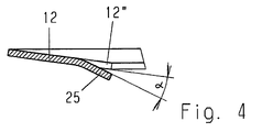
- FIGS. 3 to 6 show in plan view a part of the cooling channel cover 12, in the inner region 12 "of two juxtaposed punched 31 and 32, the tongue 25 is formed, which, as Fig. 4 , A sectional view of the cooling channel cover 12 along the line CC in Fig. 3 , is bent away from the imaginary plane formed by the cooling channel cover 12 and includes an acute angle ⁇ with the inner portion 12 "of the cooling channel cover 12.
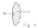
- FIG. 5 A partial section through the hub support 17 (without representation of the cooling channel cover 12) along the line AA in Fig. 2 , Shows shape and arrangement of the molded in the radial outer side of the hub support 17 recess 28 for receiving the tongue 25th
- the plate spring-shaped cooling channel cover 12 is placed on the piston lower part such that, as in Fig. 6 is shown, the tongue 25 engages in the recess 28.
- the upper piston part 2 is screwed onto the lower piston part 6, wherein the threaded bolt 19 of the piston upper part 2 is screwed into the threaded bore 23 of the region 22.
- the elasticity of the relatively thin-walled region 22 causes it to deform like a disk spring when the upper and lower piston parts 2, 6 are screwed together and bulges the inner center of the region 22, which is provided with the threaded bore 23, in the direction of the piston upper part 2.
- the conical shape of the cooling channel cover 12 is more pronounced in the relaxed state than in the installed state.
- the taper of the cooling channel cover 12 is reduced, that is, the shape of the cooling channel cover 12 is flatter, and in the cooling channel cover 12th a bias voltage is generated, which ensures after the final assembly of the piston 1, that the cooling channel cover 12 partially rests firmly in the recess 27 of the end face 26 and partly on the projection 29, and that a secure and firm installation of the cooling channel cover 12 in the piston 1 also at ensures fast reciprocating movements of the piston 1, which are common in engine operation.
Landscapes
- Engineering & Computer Science (AREA)
- Chemical & Material Sciences (AREA)
- Combustion & Propulsion (AREA)
- Mechanical Engineering (AREA)
- General Engineering & Computer Science (AREA)
- Physics & Mathematics (AREA)
- Fluid Mechanics (AREA)
- Pistons, Piston Rings, And Cylinders (AREA)
Claims (2)
- Piston refroidi et en plusieurs parties (1) pour un moteur à combustion interne comprenant :- une partie supérieure de piston (2)= qui forme le fond de piston (30),= qui présente sur la face inférieure opposée au fond de piston (30) un canal de refroidissement (10) annulaire radialement extérieur,= qui présente une paroi annulaire (4) délimitant le canal de refroidissement (10) radialement vers l'extérieur avec une partie annulaire (5) sur la face extérieure radiale de celle-ci,= sur la face inférieure de laquelle est disposée un boulon (19) agencé de manière centrale et coaxiale par rapport à l'axe de piston (18) comprenant un filetage (21),- un couvercle de canal de refroidissement (12) conçu en tant que bague de type rondelle-ressort pour fermer le canal de refroidissement (10),- une partie inférieure de piston (6),= qui présente deux bossages d'axe (8) et les éléments de tige (7) reliant les bossages d'axe (8) l'un à l'autre,= qui présente une zone (22) reliant les éléments de tige (7) et les bossages d'axe (8) les uns aux autres du côté du fond de piston, dans laquelle un alésage (23) agencé de manière centrale et coaxiale par rapport à l'axe de piston (18) est formé avec un filetage intérieur (24) passant sur le filetage (21) du boulon (19), de sorte qu'après la pose du couvercle de canal de refroidissement (12) sur une saillie (29) formée radialement à l'extérieur sur la partie inférieure de piston (6) près du canal de refroidissement (10), la partie supérieure de piston (2) et la partie inférieure de piston (6) puissent être vissées l'une avec l'autre au moyen du boulon fileté (19) et du taraudage(23), la zone radialement extérieure (12') du couvercle de canal de refroidissement (12) reposant sur la surface frontale (26) de la paroi annulaire (4) opposée au fond de piston et la zone radialement intérieure (12") du couvercle de canal de refroidissement (12) reposant sur la saillie (29) par serrage,caractérisé en ce que,- dans la zone radialement intérieure (12") du couvercle de canal de refroidissement (12), deux découpes (31, 32) orientées radialement vers l'intérieur sont ménagées avec un espacement entre elles, de telle sorte qu'il en découle entre elles une languette (25) orientée radialement vers l'intérieur,- la languette (25) forme avec la zone intérieure (12") du couvercle de canal de refroidissement (12) un angle aigu α,- la saillie (29) présente un évidement (28) radialement extérieur, dans lequel la languette (25) du couvercle de canal de refroidissement (12) vient en prise lors du vissage de la partie supérieure de piston (2) et de la partie inférieure de piston (6).
- Piston refroidi et en plusieurs parties (1) selon la revendication 1, caractérisé en ce que le couvercle de canal de refroidissement (12) est conçu en tant que bague d'une seule pièce et fermée.
Applications Claiming Priority (2)
| Application Number | Priority Date | Filing Date | Title |
|---|---|---|---|
| DE102004057624A DE102004057624A1 (de) | 2004-11-30 | 2004-11-30 | Mehrteiliger, gekühlter Kolben für einen Verbrennungsmotor |
| PCT/DE2005/002143 WO2006058524A1 (fr) | 2004-11-30 | 2005-11-28 | Piston refroidi et en plusieurs parties destine a un moteur a combustion interne |
Publications (2)
| Publication Number | Publication Date |
|---|---|
| EP1828587A1 EP1828587A1 (fr) | 2007-09-05 |
| EP1828587B1 true EP1828587B1 (fr) | 2010-02-10 |
Family
ID=35966440
Family Applications (1)
| Application Number | Title | Priority Date | Filing Date |
|---|---|---|---|
| EP05816542A Expired - Lifetime EP1828587B1 (fr) | 2004-11-30 | 2005-11-28 | Piston refroidi et en plusieurs parties destine a un moteur a combustion interne |
Country Status (6)
| Country | Link |
|---|---|
| US (1) | US7743745B2 (fr) |
| EP (1) | EP1828587B1 (fr) |
| JP (1) | JP5026983B2 (fr) |
| BR (1) | BRPI0518704A2 (fr) |
| DE (2) | DE102004057624A1 (fr) |
| WO (1) | WO2006058524A1 (fr) |
Families Citing this family (30)
| Publication number | Priority date | Publication date | Assignee | Title |
|---|---|---|---|---|
| DE102005041409A1 (de) * | 2005-09-01 | 2007-03-08 | Mahle International Gmbh | Zweiteiliger Kolben für einen Verbrennungsmotor |
| DE102005042003A1 (de) * | 2005-09-05 | 2007-03-08 | Mahle International Gmbh | Gebauter, flüssigkeitsgekühlter Kolben |
| DE102006002949A1 (de) * | 2006-01-21 | 2007-08-02 | Ks Kolbenschmidt Gmbh | Kühlkanalkolben für eine Brennkraftmaschine |
| DE102006045728A1 (de) * | 2006-09-27 | 2008-04-03 | Mahle International Gmbh | Einteiliger Kolben für einen Verbrennungsmotor |
| DE102007027162A1 (de) | 2007-06-13 | 2008-12-18 | Mahle International Gmbh | Zweiteiliger Kolben für einen Verbrennungsmotor |
| DE102007031400A1 (de) * | 2007-07-05 | 2009-01-08 | Ks Kolbenschmidt Gmbh | Einteiliger Kühlkanalkolben mit zwei miteinander verschraubten Kolbenteilen |
| JP4510061B2 (ja) * | 2007-09-18 | 2010-07-21 | 理研鍛造株式会社 | 内燃機関用ピストンの製造方法 |
| FR2925604A1 (fr) * | 2007-12-19 | 2009-06-26 | Renault Sas | Chambre de combustion pour moteur thermique a injection directe suralimente |
| DE102008055848A1 (de) * | 2008-11-04 | 2010-05-06 | Ks Kolbenschmidt Gmbh | Kühlkanalkolben einer Brennkraftmaschine mit einem Verschlusselement, das den Kühlkanal verschließt |
| DE102008056203A1 (de) * | 2008-11-06 | 2010-05-12 | Mahle International Gmbh | Mehrteiliger Kolben für einen Verbrennungsmotor und Verfahren zu seiner Herstellung |
| DE102008062219A1 (de) * | 2008-12-13 | 2010-06-17 | Mahle International Gmbh | Kolben für einen Verbrennungsmotor |
| US8807109B2 (en) * | 2009-11-06 | 2014-08-19 | Federal-Mogul Corporation | Steel piston with cooling gallery and method of construction thereof |
| CN102959222B (zh) * | 2010-06-29 | 2016-04-06 | 科尔本施密特有限公司 | 用于火花点火引擎的活塞 |
| US20130133610A1 (en) * | 2010-07-19 | 2013-05-30 | Ks Kolbenschmidt Gmbh | Method for producing a cooling channel system for internal combustion engines and piston produced in this way |
| US9856820B2 (en) * | 2010-10-05 | 2018-01-02 | Mahle International Gmbh | Piston assembly |
| DE102010056218A1 (de) * | 2010-12-24 | 2012-06-28 | Mahle International Gmbh | Kolben für einen Verbrennungsmotor |
| DE102010056220A1 (de) * | 2010-12-24 | 2012-06-28 | Mahle International Gmbh | Kolben für einen Verbrennungsmotor |
| DE102011013113A1 (de) * | 2011-03-04 | 2012-09-06 | Mahle International Gmbh | Kolben für einen Verbrennungsmotor und Verfahren zu seiner Herstellung |
| US9464592B2 (en) * | 2011-04-18 | 2016-10-11 | Achates Power, Inc. | Piston thermal management in an opposed-piston engine |
| DE102011106559A1 (de) * | 2011-07-05 | 2013-01-10 | Mahle International Gmbh | Kolben für einen Verbrennungsmotor |
| DE102011119525A1 (de) * | 2011-11-26 | 2013-05-29 | Mahle International Gmbh | Kolben für einen Verbrennungsmotor |
| DE102012014192A1 (de) * | 2012-07-18 | 2014-01-23 | Mahle International Gmbh | Kolben für einen Verbrennungsmotor |
| DE102012213558A1 (de) * | 2012-08-01 | 2014-02-06 | Mahle International Gmbh | Kolben |
| US9228480B2 (en) | 2014-06-06 | 2016-01-05 | Mahle Industries, Incorporated | Piston crown cooling gallery insert |
| DE102014015947A1 (de) * | 2014-10-30 | 2016-05-19 | Mahle International Gmbh | Kühlkanalabdeckung sowie mit einer Kühlkanalabdeckung versehener Kolben |
| US20180230937A1 (en) * | 2015-08-11 | 2018-08-16 | Ks Kolbenschmidt Gmbh | Method for Producing a Monoblock Piston, and Monoblock Piston |
| FR3040745B1 (fr) * | 2015-09-04 | 2018-07-13 | Soc De Motorisations Aeronautiques | Ensemble pour moteur a combustion interne comprenant un piston et une plaque de fermeture d'une galerie de refroidissement du piston |
| JP2017089471A (ja) * | 2015-11-09 | 2017-05-25 | いすゞ自動車株式会社 | スチールピストン、スチールピストンの冷却方法、及びスチールピストンの製造方法 |
| DE102016225635A1 (de) * | 2016-12-20 | 2018-06-21 | Mahle International Gmbh | Kolben einer Brennkraftmaschine |
| DE102018201556A1 (de) * | 2018-02-01 | 2019-08-01 | Volkswagen Aktiengesellschaft | Hubkolben für eine Hubkolbenbrennkraftmaschine und Verwendung eines Hubkolbens in einer Hubkolbenbrennkraftmaschine |
Family Cites Families (17)
| Publication number | Priority date | Publication date | Assignee | Title |
|---|---|---|---|---|
| DD252638A1 (de) * | 1986-09-17 | 1987-12-23 | Ifa Motorenwerke | Spritzoelgekuehlter eisenkolben fuer hubkolbenbrennkraftmaschinen |
| DE3719469A1 (de) * | 1987-06-11 | 1988-12-29 | Mahle Gmbh | Gebauter fluessigkeitsgekuehlter kolben fuer verbrennungsmotoren |
| DE3830033C2 (de) * | 1987-11-30 | 1998-05-07 | Mahle Gmbh | Gebauter, ölgekühlter Tauchkolben für Verbrennungsmotoren |
| IT1240526B (it) * | 1990-07-31 | 1993-12-17 | Borgo Nova S.P.A. | Perfezionamento relativo a pistoni, in genere. |
| DE4039751A1 (de) * | 1990-12-13 | 1992-06-17 | Mahle Gmbh | Mehrteililger, gekuehlter kolben fuer verbrennungsmotoren |
| DE4039754A1 (de) * | 1990-12-13 | 1992-06-17 | Mahle Gmbh | Mehrteiliger, gekuehlter kolben fuer verbrennungsmotoren |
| DE4137126A1 (de) * | 1991-07-25 | 1993-05-13 | Mahle Gmbh | Mehrteiliger, gekuehlter kolben fuer verbrennungsmotoren |
| DE4208037C2 (de) * | 1992-03-13 | 1998-03-26 | Mahle Gmbh | Mehrteiliger, gekühlter Kolben für Verbrennungsmotoren |
| DE4446726A1 (de) * | 1994-12-24 | 1996-06-27 | Mahle Gmbh | Verfahren zur Herstellung eines einteiligen Kühlkanalkolbens |
| DE19926568A1 (de) * | 1999-06-11 | 2000-12-14 | Mahle Gmbh | Gekühlter Kolben für Verbrennungsmotoren |
| DE19960913A1 (de) * | 1999-12-17 | 2001-06-21 | Mahle Gmbh | Untere Abdeckung eines Kühlraumes für Kolben von Verbrennungsmotoren |
| DE10210570A1 (de) * | 2002-03-09 | 2003-09-18 | Mahle Gmbh | Mehrteiliger gekühlter Kolben für einen Verbrennungsmotor |
| DE10221561A1 (de) * | 2002-05-15 | 2004-01-08 | Mahle Gmbh | Gekühlter Kolben für einen Verbrennungsmotor |
| US6701875B2 (en) * | 2002-05-31 | 2004-03-09 | Cummins Inc. | Internal combustion engine with piston cooling system and piston therefor |
| DE10244511A1 (de) * | 2002-09-25 | 2004-04-15 | Mahle Gmbh | Mehrteiliger gekühlter Kolben für einen Verbrennungsmotor |
| DE10257022A1 (de) * | 2002-12-06 | 2004-06-17 | Mahle Gmbh | Mehrteiliger gekühlter Kolben für einen Verbrennungsmotor |
| US6938604B2 (en) * | 2003-10-06 | 2005-09-06 | Mahle Gmbh | Cooling channel cover for a one-piece piston of an internal combustion engine |
-
2004
- 2004-11-30 DE DE102004057624A patent/DE102004057624A1/de not_active Withdrawn
-
2005
- 2005-11-28 US US11/791,777 patent/US7743745B2/en not_active Expired - Fee Related
- 2005-11-28 BR BRPI0518704-4A patent/BRPI0518704A2/pt not_active IP Right Cessation
- 2005-11-28 JP JP2007543694A patent/JP5026983B2/ja not_active Expired - Fee Related
- 2005-11-28 DE DE502005009010T patent/DE502005009010D1/de not_active Expired - Lifetime
- 2005-11-28 EP EP05816542A patent/EP1828587B1/fr not_active Expired - Lifetime
- 2005-11-28 WO PCT/DE2005/002143 patent/WO2006058524A1/fr not_active Ceased
Also Published As
| Publication number | Publication date |
|---|---|
| JP5026983B2 (ja) | 2012-09-19 |
| WO2006058524A1 (fr) | 2006-06-08 |
| DE502005009010D1 (de) | 2010-03-25 |
| JP2008522088A (ja) | 2008-06-26 |
| US7743745B2 (en) | 2010-06-29 |
| US20080121204A1 (en) | 2008-05-29 |
| DE102004057624A1 (de) | 2006-06-01 |
| EP1828587A1 (fr) | 2007-09-05 |
| BRPI0518704A2 (pt) | 2008-12-02 |
Similar Documents
| Publication | Publication Date | Title |
|---|---|---|
| EP1828587B1 (fr) | Piston refroidi et en plusieurs parties destine a un moteur a combustion interne | |
| EP1583896B1 (fr) | Piston refroidi a plusieurs parties pour un moteur a combustion interne | |
| EP2027381B1 (fr) | Piston en plusieurs parties, refroidi, pour un moteur à combustion interne | |
| EP2136088B1 (fr) | Elément de liaison doté d'une vis et d'une douille agencée sur celle-ci de façon inamovible | |
| EP2063136B1 (fr) | Elément de fixation comprenant une douille imperdable attachable | |
| EP1960653B1 (fr) | Piston en deux pieces pour moteur a combustion interne | |
| EP1920152B1 (fr) | Piston en deux parties pour moteur a combustion interne | |
| EP1636475B1 (fr) | Piston de moteur a combustion interne | |
| EP1761697B1 (fr) | Piston compose conçu pour un moteur a combustion interne | |
| EP1761698A1 (fr) | Piston compose conçu pour un moteur a combustion interne | |
| DE10325914B4 (de) | Kolben für einen Verbrennungsmotor | |
| DE102007019931A1 (de) | Verfahren zum Verschrauben zweier Metallteile | |
| EP2189644B1 (fr) | Piston en deux parties pour un moteur à combustion | |
| EP1660769B1 (fr) | Piston en plusieurs parties destine a un moteur a combustion interne | |
| DE102008020099B4 (de) | Durch mindestens eine Befestigungsschraube zu montierendes Bauteil | |
| EP1819921B1 (fr) | Piston d'un moteur a combustion interne | |
| EP1279842B1 (fr) | Système d'écrou avec rondelle pivotante | |
| DE102005060548A1 (de) | Zweiteiliger Kolben für einen Verbrennungsmotor | |
| DE19905706C2 (de) | Kombimutter mit schräger Unterlegscheibe | |
| DE202019002530U1 (de) | Einpresselement, Anordnung und Vorrichtung | |
| DE102005044597A1 (de) | Kolben für einen Verbrennungsmotor | |
| EP2002104B1 (fr) | Pièce supérieure d'un piston assemblé | |
| DE19823475A1 (de) | Verbindungselement |
Legal Events
| Date | Code | Title | Description |
|---|---|---|---|
| PUAI | Public reference made under article 153(3) epc to a published international application that has entered the european phase |
Free format text: ORIGINAL CODE: 0009012 |
|
| 17P | Request for examination filed |
Effective date: 20070615 |
|
| AK | Designated contracting states |
Kind code of ref document: A1 Designated state(s): DE FR GB |
|
| 17Q | First examination report despatched |
Effective date: 20071010 |
|
| RBV | Designated contracting states (corrected) |
Designated state(s): DE FR GB |
|
| DAX | Request for extension of the european patent (deleted) | ||
| GRAP | Despatch of communication of intention to grant a patent |
Free format text: ORIGINAL CODE: EPIDOSNIGR1 |
|
| GRAS | Grant fee paid |
Free format text: ORIGINAL CODE: EPIDOSNIGR3 |
|
| GRAA | (expected) grant |
Free format text: ORIGINAL CODE: 0009210 |
|
| AK | Designated contracting states |
Kind code of ref document: B1 Designated state(s): DE FR GB |
|
| REG | Reference to a national code |
Ref country code: GB Ref legal event code: FG4D Free format text: NOT ENGLISH |
|
| REF | Corresponds to: |
Ref document number: 502005009010 Country of ref document: DE Date of ref document: 20100325 Kind code of ref document: P |
|
| PLBE | No opposition filed within time limit |
Free format text: ORIGINAL CODE: 0009261 |
|
| STAA | Information on the status of an ep patent application or granted ep patent |
Free format text: STATUS: NO OPPOSITION FILED WITHIN TIME LIMIT |
|
| 26N | No opposition filed |
Effective date: 20101111 |
|
| PGFP | Annual fee paid to national office [announced via postgrant information from national office to epo] |
Ref country code: GB Payment date: 20141121 Year of fee payment: 10 Ref country code: DE Payment date: 20141126 Year of fee payment: 10 |
|
| PGFP | Annual fee paid to national office [announced via postgrant information from national office to epo] |
Ref country code: FR Payment date: 20141120 Year of fee payment: 10 |
|
| REG | Reference to a national code |
Ref country code: DE Ref legal event code: R119 Ref document number: 502005009010 Country of ref document: DE |
|
| GBPC | Gb: european patent ceased through non-payment of renewal fee |
Effective date: 20151128 |
|
| REG | Reference to a national code |
Ref country code: FR Ref legal event code: ST Effective date: 20160729 |
|
| PG25 | Lapsed in a contracting state [announced via postgrant information from national office to epo] |
Ref country code: GB Free format text: LAPSE BECAUSE OF NON-PAYMENT OF DUE FEES Effective date: 20151128 Ref country code: DE Free format text: LAPSE BECAUSE OF NON-PAYMENT OF DUE FEES Effective date: 20160601 |
|
| PG25 | Lapsed in a contracting state [announced via postgrant information from national office to epo] |
Ref country code: FR Free format text: LAPSE BECAUSE OF NON-PAYMENT OF DUE FEES Effective date: 20151130 |